In this paper, a novel triple-band circular-ring monopole antenna with a half-circular ring and ground slot for wireless local area network/Worldwide Interoperability of Microwave Access (WLAN/WiMAX) applications is proposed. The proposed antenna consists of one circular ring, a half-circular ring and a rectangular slot in the ground plane. Based on the concept, a prototype of the proposed triple-band antenna was designed, fabricated and tested. The numerical and experiment results demonstrated that the proposed antenna satisfied the -10 dB impedance bandwidth requirement while simultaneously covering the WLAN and WiMAX bands. Furthermore, this paper presents and discusses the 2D radiation patterns and 2D gains according to the results of the experiment.
With the rapid development of wireless technology, there has been a great demand for wireless devices with multi-standard applications. Wireless local area network (WLAN) technology is one of the most successful and fastest-growing wireless communications technologies in the world today. Among the components of WLAN-enabled consumer electronic devices, the antenna plays an important role in the key components that determine the radio frequency performance of the end-product. Therefore, as WLAN communications become increasingly popular, the need for a WLAN antenna that is low-profile, lightweight, flush-mounted WLAN antenna with a simple structure is growing. Furthermore, Worldwide Interoperability of Microwave Access (WiMAX) has been deployed to provide mobile broadband Internet services with large coverage areas in many countries [1,2]. Therefore, for its short- and long-range applications in modern wireless communication systems, we need multiband and broadband antennas that simultaneously meet WLNA and WiMAX standards. To come up with multiand wide-band WLAN/WiMAX antennas, various types of antenna designs for WLAN/WiMAX band operation have been reported [3-12].
Among such antennas, printed monopole antennas play an important role due to their attractive features, which include of a simple structure, a low profile, and reasonably good performance. Among printed monopole antennas, the circular-ring monopole antenna [5-7,13-21], the ring monopole antenna with double-coupled C-shaped strips [5], the dual-band ringshaped antenna [6], and the ring monopole antenna with a defected ground plane [7] for WiMAX/WLAN application have been studied. In particular, the double-coupled C-shaped strips [5] antenna is designed and fabricated at a substrate with a relative permittivity of 2.65. This proposed antenna is made of expensive materials, unlike the conventional FR4 materials. The circular-ring, printed monopole antenna [13], the M-shaped antenna surrounded by a ring monopole [14] for wideband operations, the band-notched circular-ring monopole antenna [15-17], the CPW dual-ring loop antenna for dual-band operation [18], the ring monopole UWB antenna with a band notch [19] and the compact-ring monopole antenna for Wi-BAN [20], and the CPW-fed circular-ring monopole with an inverted T-strip line for dual-band operation [21] have already been proposed.
In this study, a novel microstrip-fed monopole antenna for WLAN and WiMAX band applications was designed. The study goals were achieved by properly selecting the dimensions of the proposed antenna, good triple-broadband bandwidth capabilities, and suitable radiation characteristics for two multiband wireless communication systems, WLAN (2.4–2.484 and 5.15–5.85 GHz) and WiMAX (2.5–2.69, 3.3–3.7, and 5.25– 5.85 GHz) operations. The antenna configuration and simulation data, as well as the constructed prototype and measurement data, will be carefully examined and discussed in the succeeding sections.
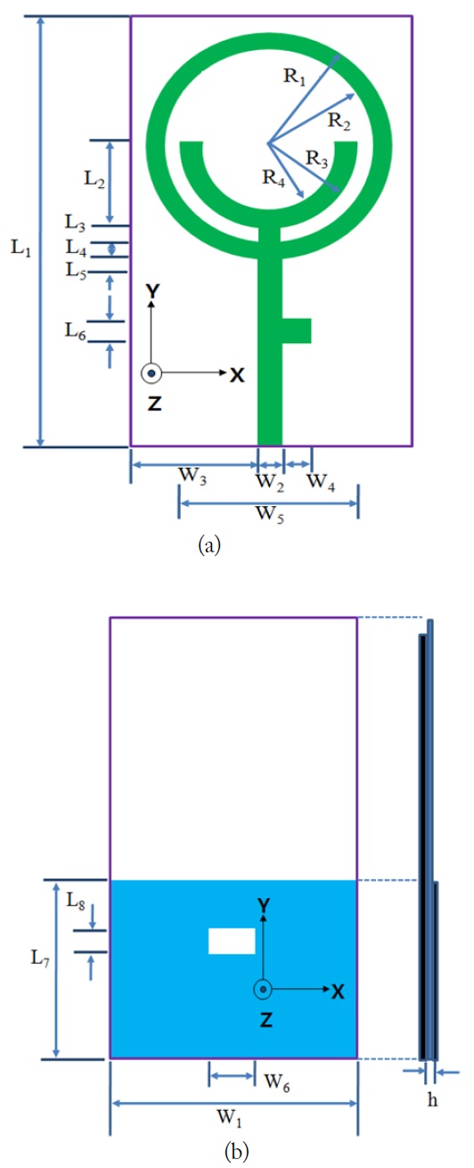
The schematic configuration of the proposed design of the WLAN/WiMAX printed monopole antenna is shown in Fig. 1. The proposed antenna is based on a circular-ring planar monopole design. To satisfy the specifications of the 3.5 GHz WiMAX and the 5 GHz WLAN/WiMAX bands, a halfcircular ring and rectangular slot in the ground plane were introduced in this design of the proposed antenna, respectively. The total sizes of the substrate and the ground plane of the proposed antenna were 25.0 × 42.0 mm2 (
The proposed antenna had one circular ring and one halfcircular ring with a uniform width for design convenience. In this design, the first circular-ring was resonant for the 2.4/2.5 GHz WLAN/WiMAX and 5 GHz WLAN/WiMAX bands. To obtain the resonance of the 3.5 GHz bands for the WiMAX operation, the half-circular ring was introduced. To satisfy the specifications for the 5 GHz WLAN/WiMAX bands, a 6.0 × 2.0 mm2 (
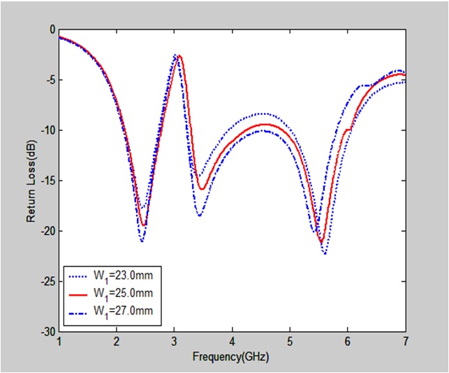
1. Effect of the Ground Plane (W1)
Fig. 2 illustrates the return loss for the different values of the ground plane. The figure shows that the impedance bandwidth and characteristics of the return loss slightly changed when
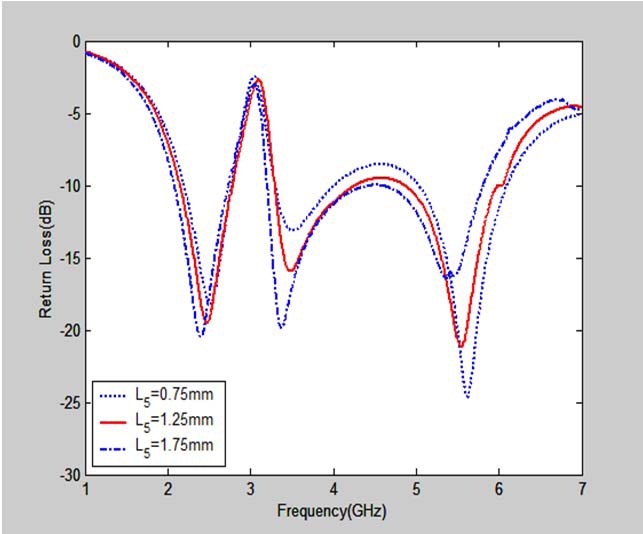
2. Effect of the Gap Length between Circular Ring and the Ground Plane (L5)
Fig. 3 illustrates the return loss for the different values of the gap length between the proposed the circular ring and the ground plane. It can be seen in the figure that the impedance bandwidth and characteristics of the return loss somewhat changed when
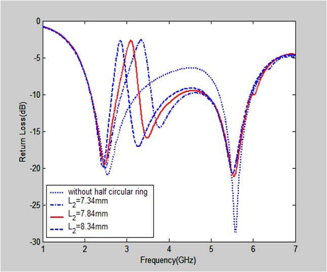
3. Effect of the Half-Circular Ring Length
Fig. 4 illustrates the return loss for the different values of the half-circular ring length. The figure shows that the half-circular ring was used to generate the second resonant mode at the 3.5 GHz WiMAX band. The 3.5 GHz band resonance was not generated when the half-circular ring did not exist. This implies that the length of the half-circular ring is greatly affected by the characteristics of the return loss in the 3.5 GHz band. Thus, the length of the rectangular strip should be considered when determining the proper parameters for the proposed design, to achieve the 3.5 GHz operating band. To design a good tripleband WLAN/WiMAX operation,
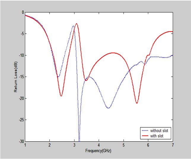
4. Effect of the Rectangular Slot in the Ground Plane
Fig. 5 shows the return loss with and without a rectangular slot in the ground plane. It can be seen in the figure that the resonant frequency was not generated in the 5 GHz band, and that the return loss had wideband characteristics when there was no rectangular slot in the ground plane. These indicate that the return loss of the 5 GHz band in the proposed antenna heavily depends on the rectangular slot in the ground plane. Certainly, with the variation of the width and length in the rectangular slot in the ground plane, the return loss can be maintained at less than –10 dB, thus covering the frequency bandwidths for WLAN (2.4–2.484, 5.15–5.35, and 5.75–5.85 GHz) and WiMAX (2.5–2.69, 3.4–3.7, 5.15–5.35, 5.47–5.725, and 5.725 –5.825 GHz).
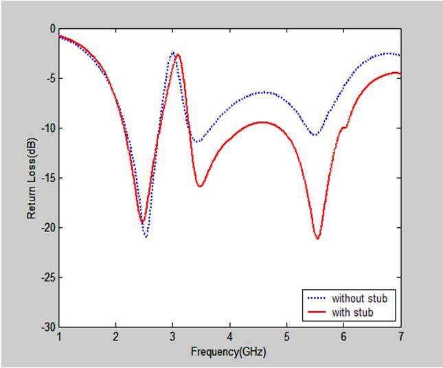
5. Effect of the Rectangular Stub in the Feed Line
Fig. 6 shows the return loss with and without a rectangular stub in the feed line. It can be seen in the figure that resonant frequencies were generated in the 3.5 GHz and 5 GHz bands when there was no rectangular stub in the feed line in the required frequency bands. However, the characteristics of the return loss deteriorated for the WLAN and WiMAX operations. Also, the impedance bandwidth did not match the required frequency bands. However, it can be seen in the figure that the characteristics of the return loss improved and the impedance bandwidth matched the required frequency band when there was a rectangular stub in the feed line. Thus, to fully satisfy the specifications of WLAN/WiMAX operations, a 6.0 × 2.0 mm2 (
The values of the design parameters shown in Fig. 1 were calculated using the optimized Ansoft HFSS. Thus, the dimensions of the proposed antenna were set as follows:
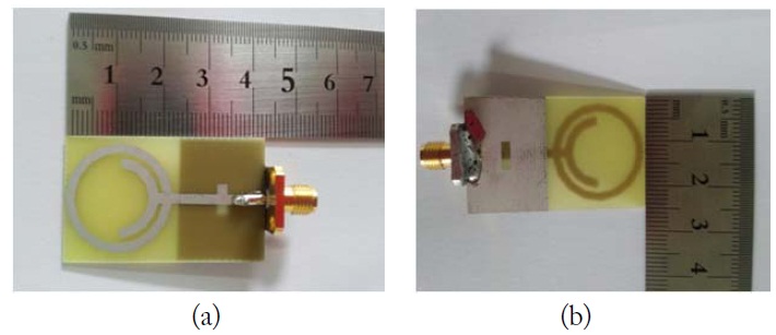
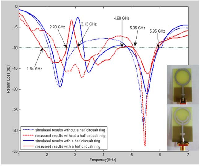
Based on the design dimensions, a prototype of the proposed triple-band WLAN/WiMAX antenna was fabricated and measured. A prototype of the proposed antenna was fabricated with the aforementioned design parameters and is shown in Fig. 7(a) and (b). The results were obtained using the Anritsu MS4644A vector network analyzer in Silla University, Busan, Korea. The far-field radiation patterns and gains were measured using a farfield anechoic absorber obtained from Foxconn Corporation in Korea. Simulated and measured return loss characteristics for the dual-band WLAN antenna without a half circular ring and the proposed antenna triple band antenna with a half-circular ring are compared in Fig. 8. As shown in Fig. 8, it is observed that 3.5 GHz band resonance is affected by using a half-circular ring and simulated and experimental return losses are generally acceptable agreements between them was achieved. As the simulation used a waveguide port, and as an SMA connector was used for the measurement, there is a difference between the measurement and simulation results. To confirm the accuracy of the return loss characteristics of the designed antenna, it is recommended that the antenna be manufactured and measured more carefully. The measurement results showed that three relative impedance bandwidths with –10 dB return losses of about 860 MHz (37.89%, 1,840–2,700 MHz), 1,470 MHz (38.03%, 3,130–4,600 MHz) and 900 MHz (16.36%, 5,050– 5,950 MHz), respectively, can satisfy the typical bandwidth requirement for the 2.4–2.484 and 5.15–5.825 GHz WLAN and the 2.5–2.69, 3.4–3.7, and 5.25–5.85 GHz WiMAX bands, respectively.
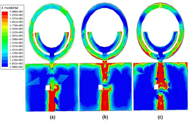
Theoretically, HFSS was used to evaluate and verify the three resonant frequencies of 2.48, 3.58, and 5.61 GHz, which mainly depended on the lengths of the different current paths along the circular ring with a half-circular ring. As expected, it was evident that the different surface currents were excited by the 2.48 and 5.61 GHz frequencies. Fig. 9(a)–(c) show the surface current density excitations along the circular-ring antenna in the cases of the three resonant frequencies of 2.48, 3.58, and 5.61 GHz, respectively. As shown in Fig. 9(a), the lowest band surface current density excitations along the circular ring and the half-circular ring were observed when the resonant frequency was 2.48 GHz. Thus, it is implied that the 2.4/2.5 GHz band excitation was contributed by the circular ring patch and a halfcircular ring patch. As observed in the 3.5 GHz band excitation in Fig. 9(b), a larger surface current density was observed flowing along the half-circular ring when the resonant frequency was 3.58 GHz. Thus, it is implied that the 3.5 GHz band excitation was contributed by the half-circular ring patch. As shown in Fig. 9(c), however, larger surface current densities were observed as flowing along the rectangular slot in the ground plane when the resonant frequency was 5.61 GHz. Thus, it is implied that the 5 GHz band excitation was contributed by the circular ring patch and by the rectangular slot in the ground plane.
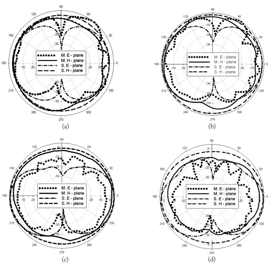
Fig. 10 shows the simulated and measured 2D far-field radiation patterns in the E-plane (x-z plane) and H-plane (y-z plane). Fig. 10(a)–(d) show the 2D simulated and measured radiation patterns at 2,500, 3,500, 5,300, and 5,700 MHz, respectively. Based on these measured radiation patterns, the proposed antenna displayed nearly omnidirectional radiation characteristics in the H-plane and monopole-like radiation pattern characteristics in the E-plane at the considered frequencies.
Fig. 11 shows the 2D measured antenna peak and average gain for the frequencies across the 2.4/2.5, 3.5, and 5 GHz bands. The 2.4/2.5 GHz band had an antenna peak gain level of about 1.59 to 2.93 dBi, and the 3.5 GHz band, about 1.20 to 2.39 dBi. The measured antenna gain levels were about 0.71 to 2.43 dBi in the 5 GHz band. The 2.4/2.5 GHz band had an antenna average gain level of about –2.74 to –2.26 dBi, and the 3.5 GHz band, about –3.87 to –2.82 dBi. The measured antenna gain levels were about –5.11 to –2.26 dBi in the 5 GHz band. The 2.4/2.5 GHz band had an antenna simulated gain level of about 0.57 to 1.22 dBi, and the 3.5 GHz band, about –1.15 to 2.10 dBi. The measured antenna gain levels were about 3.9 to 4.22 dBi in the 5 GHz band. As shown in Fig. 11, there are small discrepancies between the simulation and measurement results. These discrepancies may have occurred: first, as the simulation used a waveguide port, an SMA connector was used for the measurement. The effect of the SMA conductor broadened the size of the ground plane. As a result, SMA conductor could have caused these discrepancies. Second, the effect of the lossy substrate material was influenced on radiation patterns and gains. Practically, permittivity and lossy tangent of substrate material is different from those of simulation model each other. These results may have been due to these discrepancies Third, as the simulation used infinite boundary conditions to obtain a far field, an artificial wave absorber was used to obtain measurement of the far field. These results may have caused the difference between the measurement and simulation results.
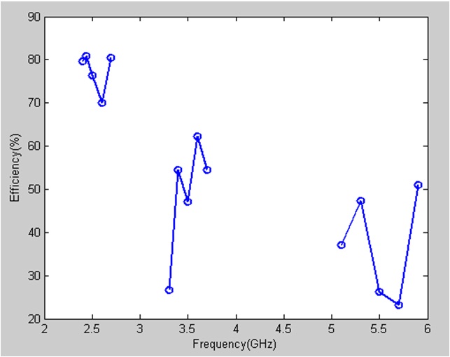
Fig. 12 shows the measured radiation efficiencies for the frequencies across the 2.4/2.5, 3.5, and 5 GHz bands. The 2.4/2.5 GHz band had a radiation efficiency level of about 76.41–80.9%, and the 3.5 GHz band had a radiation efficiency of about 26.61–62.17%. The measured antenna gain levels were about 23.16–54.04% in the 5 GHz band.
A circular-ring planar monopole antenna with a half-circular ring and ground slot for WLAN/WiMAX applications was proposed. Applying the circular ring and half-circular ring will enable the proposed antenna to yield two different resonances (2.5/3.5 GHz bands) to cover the desired bands. Also, the rectangular slot in the ground plane will enable the proposed antenna to yield 5 GHz band resonances to cover the desired bands. The results of the parametric studies on the proposed antenna are discussed herein. In particular, the rectangular stub depended heavily on the return loss characteristics of the proposed antenna in the 3.5 GHz and 5 GHz bands. Furthermore, the results of the studies on the surface current distributions of the operating frequencies are discussed herein. The measurement results showed that the obtained impedance bandwidths were 860 MHz (37.89%, 1,840–2,700 MHz), 1,470 MHz (38.03%, 3,130–4,600 MHz), and 900 MHz (16.36%, 5,050– 5,950 MHz), respectively, which are suitable for WLAN and WiMAX applications. In addition, the proposed antenna showed good radiation characteristics and gains in the three operating bands.