Natural gas is expected to play a central role in meeting the world’s mounting energy demand in the coming decades because it is readily available and the cleaner energy alternative to oil and coal. Thus, there is greater reliance on it today. This is especially important in view of rising concern with environmental pollution and nuclear power plant hazards. This reliance has brought about the need to develop new Liquefied Natural Gas (LNG) projects and innovate technologies to meet the global demand.
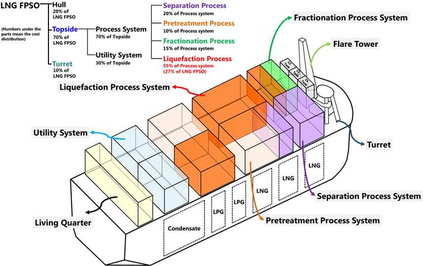
With the increasing demand for natural gas, Floating LNG (FLNG), aka LNG Floating Production Storage and Offloading (FPSO), is an effective and realistic way of exploiting, recovering, storing, transporting and propagating end-use applications of marginal gas fields and offshore associated gas resources. An FLNG consists of a hull, a turret and a topside. The topside has two parts: a process system and a utility system (Hwang et al., 2013). The process system consists of separation, pretreatment, fractionation and liquefaction, as shown in Fig. 1.
The liquefaction process system, which liquefies natural gas into LNG, is regarded as primary among all topside systems in FLNG. As shown in Fig. 1, the liquefaction process system typically accounts for 70 percent of the capital cost of the topside process system and 30-40 percent of the overall FLNG cost, so its optimal liquefaction cycle must be determined.
The liquefaction cycle has seven main equipment parts: a compressor, condenser, expansion valve, evaporator, phase separator, common header and tee. Many types of liquefaction cycles were determined according to their respective syntheses. The synthesis of the liquefaction cycles is the step in the design wherein the engineer selects the component parts and how to interconnect them to create the flowsheet of the liquefaction process system (Nishida et al., 1981). Since the area available for the liquefaction cycle in offshore applications is smaller than that in an onshore plant, various FLNG alternative liquefaction cycles must be evaluated using process syntheses to select the optimal one. For the optimal synthesis, some specific objectives, which are the design criteria in the FLNG liquefaction cycle, are needed like efficiency and reliability.
To design the FLNG liquefaction cycle, the engineer should review the liquefaction cycles that had been effectively used in onshore plants by adding, rearranging and eliminating equipment parts. During this kind of modification, the engineer should check if this modification is reasonable or not, and he or she may unintentionally miss some of the better alternative liquefaction cycles. Moreover, if beginners in the liquefaction process system field want to understand the modified cycles, comment on an idea and make more modifications, they should have knowledge on the liquefaction cycles.
In this paper, an ontological modeling that can automatically generate various alternative liquefaction cycles is proposed to help design the optimal liquefaction cycle. The ontology for modeling the liquefaction cycles includes the rules for designing the liquefaction cycle by combining the equipment parts. These rules are extracted from the liquefaction cycles used in onshore plants. The SES, which hierarchically represents the elements of a system and their relationships, is adopted for the creation of an ontological modeling framework.
The rest of this paper is as follows. Section 2 presents related studies on modeling and analysis of liquefaction cycle for FLNG Front-End Engineering Design (FEED). Section 3 reviews conventional liquefaction cycles used in onshore plants and extract some rules for configuring a liquefaction cycle, and section 4 shows the concept of the SES mainly used on this paper. Section 5 shows an ontological modeling sequence of liquefaction cycle using the SES, and proposed general rules to configure the liquefaction cycle included in the proposed SES. In section 6, the pruning sequence, which was performed to generate an alternative of liquefaction cycle from the SES, was described detailed, and the results of generating various alternatives of liquefaction cycle was shown. Finally, section 7 presents the conclusions and future directions.
In recent years, researchers applied various approaches to study design of liquefaction cycle for FLNG, especially focused on process simulation. In section 2.1, the difference between onshore and offshore plants is reviewed. Sections 2.2 reviews a design of liquefaction cycle for FLNG FEED and some previous studies on process simulation.
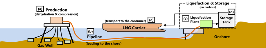
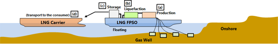
Among the proven natural gas reserves in the world, about one-third is in offshore fields. Until now, natural gas in an offshore production site is transported by a pipeline to the onshore LNG plant, where the natural gas is liquefied. As shown in Fig. 2, a traditional onshore plant for offshore gas reserves usually includes an offshore platform for dehydration and compression (Fig. 2(a)), large pipelines leading to the shore (Fig. 2(b)), an onshore liquefaction plant (Figs. 2(c) and (d)), and a harbor to accommodate LNG carriers (Fig. 2(e)).
Offshore gas reserves are often considered stranded. Much of the world’s gas reserves are in offshore fields, though onshore LNG processing is generally favored. As a result, there is growing interest in unlocking and monetizing these reserves with floating facilities that are capable of liquefying and storing natural gas.
An LNG FPSO facility, as a stand-alone unit, must have all the systems of an onshore baseload LNG facility, like its own power and heat generation unit and all other necessary utilities (Fig. 3). An FLNG facility in an offshore field site takes away the need for gas compression platforms, long subsea pipelines for transporting the natural gas to an onshore LNG plant, and onshore construction, including an onshore LNG plant, roads, storage yards and accommodation facilities.
Compared with other exploration technologies such as direct pipeline transfer, FLNG is a more effective and realistic way to exploit and use marginal gas fields and offshore associated gas fields, where a pipeline network is not available, with limited recoverable reserves and few wells (Gu and Ju, 2008). This floating plant can produce and store LNG in the sea and transfer the LNG product through offloading facilities to LNG carriers and to the world market. Moreover, FLNG is considered a major attraction in a supply-short environment, and it consists of a mobile production unit that can be moved to a new location once the existing field is depleted. Therefore, FLNG can accelerate LNG development.
LNG plants in FLNG facilities have demands on equipment that differ from those of traditional onshore LNG plants. While thermodynamic efficiency and train capacity are undoubtedly the important performance parameters for onshore natural gas fields, for FLNG facilities, other aspects are important. Offshore plants have considerably smaller footprints, higher demand for process safety, and high flexibility. They should also sometimes be able to handle various gas compositions. Furthermore, the LNG process should be able to cope with varying environmental conditions. Ship motion is known to aggravate the performance of some equipment, like the heat exchanger. A proven and optimized technology remains very important, however, due to the high uptime demand.
>
Design of liquefaction cycle for FEED of FLNG
Offshore plants consist of two main systems: a topside system and a hull system. With regard to the main function of an FLNG, the importance of topside systems is far greater than that of hull systems. The fields of engineering related to topside systems include offshore process, piping, mechanical, instrumentation, electrical, and outfitting engineering. Among these, offshore process engineering comprises the majority of topside system engineering.
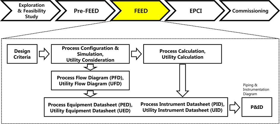
The process engineering of offshore production plants is divided into two phases: the front-end engineering design (FEED) phase and the detailed engineering phase (Hwang et al., 2012). Of these two phases, the FEED phase is more critical for determining the feasibility of specific well area development. An economic analysis of the development of a specific well area is performed based on the outputs of the FEED phase. Based on the results of this analysis, the detailed engineering phase is executed if the value of the development is sufficiently large.
The main sequence of the process engineering of offshore plants and the offshore process FEED activities are shown in Fig. 4. There are numerous liquefaction cycle alternatives, including conventional ones like the DMR and C3MR cycles. Moreover, the engineer can suggest new liquefaction cycles with regard to the mechanical feasibility of the liquefaction cycle. To select the best one among these alternatives, they should be evaluated according to the design criteria. Thus, design criteria such as the engineering considerations of equipment, instruments, and pipes on topside systems are first determined after establishing the customer requirements. The key criteria that influence process selection and plant optimization for the offshore liquefaction cycle lead to some trade-offs and compromises between efficiency and simplicity. As mentioned in the previous section, offshore plants should also consider smaller carbon footprints, the higher demand for process safety, and high flexibility, and as such, these conditions should also be considered design criteria.
Process simulation is a widely used technique for analyzing the efficiency of the liquefaction cycle. Lee et al. (2002) determined the optimal operating conditions for the single mixed-refrigerant (SMR) cycle to minimize the power required for the compressors in the cycle, by formulating a mathematical model of the cycle. Jensen (2008) also determined the optimal operating conditions of the SMR cycle by formulating a mathematical model. While a mathematical model of the SMR cycle was the focus of a study conducted by Lee et al. (2002), nine cases, including those that were formulated, and the optimal operating conditions in each case, were obtained. Venkatarathnam (2008) determined the optimal operating conditions of various cycles, including those of the DMR cycle, to maximize their efficiency. Instead of formulating a mathematical model of the cycle, ASPEN Plus was used. Furthermore, the optimization problem was solved using the Sequential Quadratic Programming (SQP) method. These researches, however, focused on only one or two liquefaction cycles. Thus, this study focused on generating various liquefaction cycle alternatives and on aiding the evaluation of liquefaction cycles in terms of efficiency, availability, etc.
CONVENTIONAL LIQUEFACTION CYCLES USED IN ONSHORE PLANTS
The LNG industry has a 45-year history, starting with the construction of the Camel plant in Algeria in 1964 (Barclay and Denton, 2005). In the 1970s, the Air Products and Chemicals Inc. (APCI) improved the liquefaction process, and this improved process continues to be used today. Since interest in LNG grew in the last decade, however, there have been considerable developments and diversification of liquefaction processes.
Liquefaction processes can generally be divided into three basic conditions: the number of cycles, the turbine-based cycle and the use of a mixed refrigerant (Hwang, 2013). The number of cycles is the number of working recycles in which the refrigerant was used for the precooling, liquefaction, and subcooling. If the liquefaction cycle has two recycles for the precooling and liquefaction, it means “two cycles” or “dual cycles.”
The turbine-based cycle is a cycle with an expander. The expander in this cycle generates work that is recovered by the turbo compressor. This cycle can be compensated for by a simple configuration, a low equipment count, and ease of startup and shutdown. The expander can expand less refrigerants than can the expansion valve, however, and cannot expand the liquefied refrigerant. Thus, for large-scale LNG liquefaction, the expansion valve is used instead of the expander.
The use of a mixed refrigerant means the cycle is operated with a mixed refrigerant instead of a pure refrigerant like nitrogen or methane. The mixed refrigerant has combined hydrocarbon components. In most gas industries, refrigerants are mixtures of propane (C3), ethane (C2) and methane (C1), and often have a small amount of nitrogen (N2). The proportion of each component can be adjusted according to the composition of each gas field. Such a mixture evaporates over a temperature trajectory rather than at a constant evaporation point. This has significant benefits to the total process. The refrigeration effect will be distributed over a range of temperatures, and accordingly, the overall difference between the temperatures of the natural gas and the mixed refrigerant will be small. This will lead to smaller driving temperature differences and a more efficient liquefaction process.
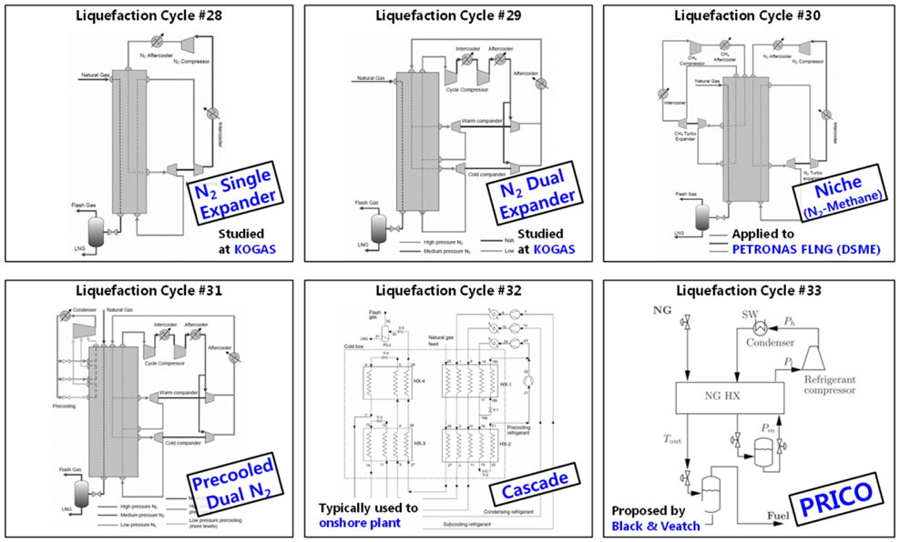
Many conventional liquefaction cycles are used in onshore plants. In this paper, six representative liquefaction cycles are introduced in the next section.
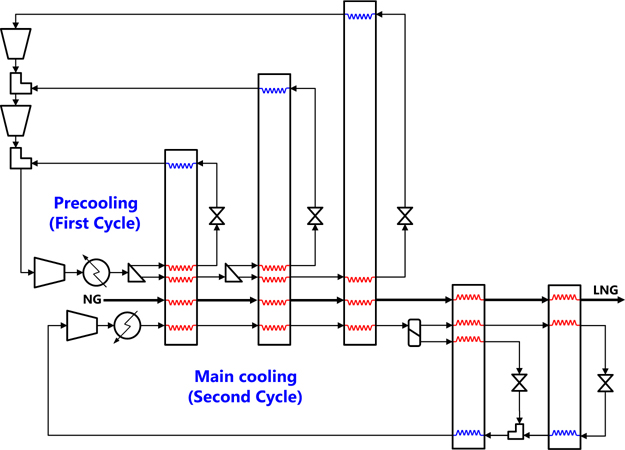
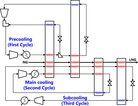
DMR cycle is categorized by the following terms: dual cooling cycles, cycles without a turbine, use of mixed refrigerants. Mixed-refrigerant technology has been assessed for offshore liquefaction based on both the SMR (single mixed-refrigerant) and DMR cycles. The DMR cycle consumes less power but is more complex, as shown in Fig. 5. It is based on dual cooling cycles with mixed refrigerants. Each cycle has multiple compressions and regenerations to enhance the efficiency of the liquefaction cycle.
Shell, a multinational oil company that is among the largest oil companies in the world, has concluded that the single mixed refrigerant is suitable for smaller LNG production capacities of approximately 2 Million Tons Per Annum (MTPA), whereas the dual mixed-refrigerant cycle is suitable for capacities of up to 5 MTPA (Bliault, 2001). A dual mixed-refrigerant process forms part of Shell’s onshore Sakhalin Island liquefaction project, with a capacity of 4.8 MTPA per train.
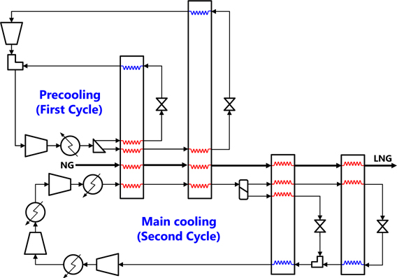
C3MR cycle is categorized into the following terms: dual cooling cycles, cycles without a turbine, and use of a pure refrigerant for precooling and a mixed refrigerant for liquefaction. The C3MR cycle is the most commonly used process in baseload onshore liquefaction plants. Its configuration is shown in Fig. 6. As the figure shows, the C3MR cycle is composed of dual cooling cycles. The precooling cycle uses a pure propane refrigerant, and the liquefaction cycle uses a mixed refrigerant, a combination of hydrocarbon components. The precooling cycle has triple compressions and triple expansions with heat regeneration. The liquefaction cycle has only one compression and dual expansions with heat regeneration.
Cascade cycle is categorized into the following terms: triple cooling cycles, cycles without a turbine, and use of pure refrigerants. In this cycle, natural gas is cooled, condensed and subcooled in heat exchange with propane, ethylene (or ethane) and finally, methane, in three discrete stages (Wood et al., 2007). Each refrigerant circuit normally has three or four refrigerant expansion and compression stages. After the compression, propane is condensed with cooling water or air; ethylene, with evaporating propane; and methane, with evaporating ethylene. This cycle was typically used in onshore plants before the 1980s, and is currently used for large-capacity LNG production.
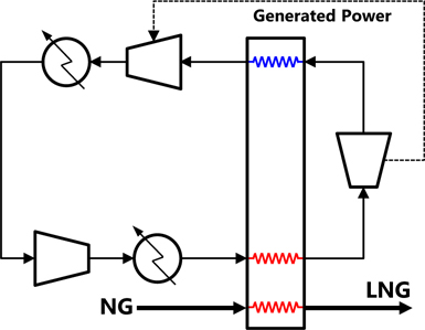
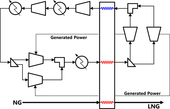
This cycle is categorized into the following terms: single cooling cycle, cycles with a turbine, and use of a pure refrigerant. In its simplest form, refrigeration is provided through compression and work expansion of a single component gas stream. High-pressure-cycle gas is cooled in counter-current heat exchange with the returning cold-cycle gas. At an appropriate temperature, the cycle gas is work-expanded to reduce its temperature via its expansion through a Joule-Thomson valve. Useful work is generated and usually recovered through a booster-compressor brake, which supplements the main cycle compressor.
The cold low-pressure gas stream from the expander is returned through various stages of heat exchange where its refrigeration is given up to the incoming natural gas and the incoming cycle gas. The warmed cycle gas is recompressed by the main cycle compressor and the booster-compressor. The refrigerant cycle gas can be either methane or nitrogen. Nitrogen permits subcooling of the natural gas to temperatures low enough to eliminate flashing at the letdown of the LNG. The nitrogen expander cycle is categorized into how many expanders are used in the cycle, as shown in Figs. 8 and 9.
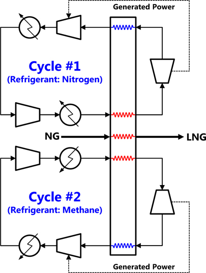
This cycle is categorized into the following terms: dual cooling cycles, cycles with turbines, and use of pure refrigerants. Using refrigerants other than nitrogen, like methane, or using a mixture of gaseous refrigerants (e.g., nitrogen and helium), can also improve the thermal efficiency. This cycle is similar to the N2 expander cycle. It has dual cooling cycles with expanders. One cycle uses methane as a refrigerant, and the other, nitrogen.
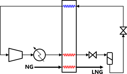
Poly-Refrigerant Integrated Cycle Operations (PRICO) cycle is categorized into the following terms: single cooling cycle, cycle without a turbine, and use of a mixed refrigerant. PRICO process is a common LNG production process, and is developed and marketed by Black and Veatch Company. Fig. 11 shows its configuration. It is the simplest form of the mixed-refrigerant cycle and has a single cooling cycle. It consists of six equipment parts: a compressor, a condenser, a heat exchanger, two expansion valves, and a phase separator. The mixed refrigerant is compressed and passes through the main heat exchanger, where it is condensed. Then it is expanded across an expansion valve (Joule-Thomson valve) and evaporated as it returns countercurrently through the heat exchanger and back to the compressor.
SYSTEM ENTITY STRUCTURE: AN ONTOLOGICAL FRAMEWORK
Ontology is a study concerned with the nature of existence of things and their relationships. It contains elements, attributes of the elements and relationships between elements with which to represent or model knowledge of a certain domain. There are many methods of representing the ontology of domain knowledge. In this thesis, the System Entity Structure (SES) is adopted to express the ontology for the liquefaction cycle.
The SES is a formal ontology framework that hierarchically represents the elements of a system and their relationships (Lee and Zeigler, 2010). It provides a model for structurally describing knowledge of a domain. Since it starts with the representation of the model structure, it is easily accommodated in modeling and simulation for automation. While it rigorously represents complex data, it has the flexibility and efficiency needed to change the model structure according to various choices.
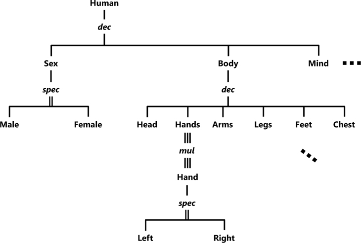
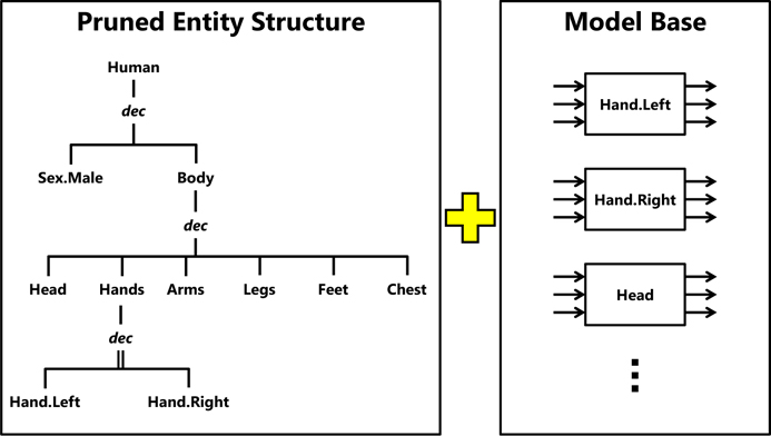
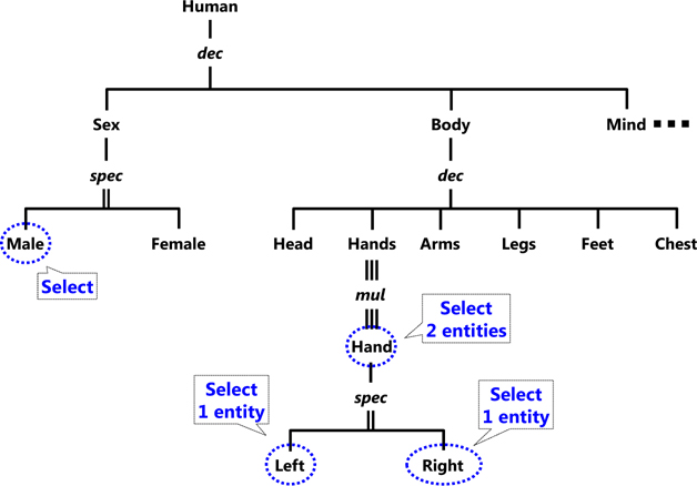
Fig. 12 shows an example of the representation of a human using the SES. Entities such as
Decomposition, noted as
Multiple decomposition, which is noted as
Specialization, noted as
Decomposition and multiple decomposition express the subsystem of a system, so they have the rules for relationships between their subsystems. In Fig. 12,
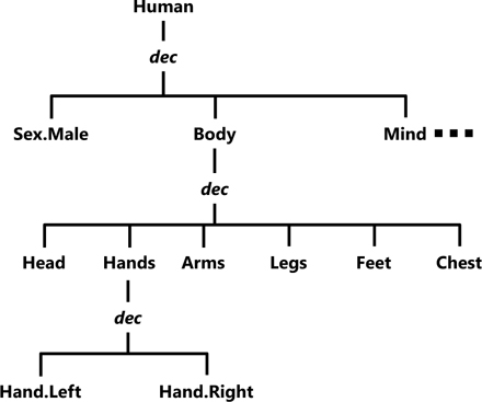
A Pure Entity Structure (PES) is one with no specializations and at most, one decomposition hanging from each entity. It is created via pruning, which is the SES operation that changes the model structure to extract specific information. It cuts off the unnecessary structure in the SES based on the specification of a pragmatic frame. It includes these processes: (a) assignment of particular values to the entity variables, and (b) trimming of the SES and determination of the minimal SES for end-users by picking specific elements from multiple choices. The pruning process reduces the choices in specialization. After its completion, there should be no choice left in the aforementioned relations. Moreover, at the implementation level, a pragmatic frame can choose anything in the ontology. The result of pruning is a pruned entity structure that contains no specialization but the original SES and therefore, specifies a smaller family of alternative models.
Fig. 13 shows the pruning procedure. Since the entity
Because of the nodes like the specialization and multiple decomposition nodes, the pruning process can make various alternative models from the SES of a certain domain. In addition, if there is a method of choosing the child entities of the specialization and multiple decomposition nodes, the pruning process can automatically generate alternative models.
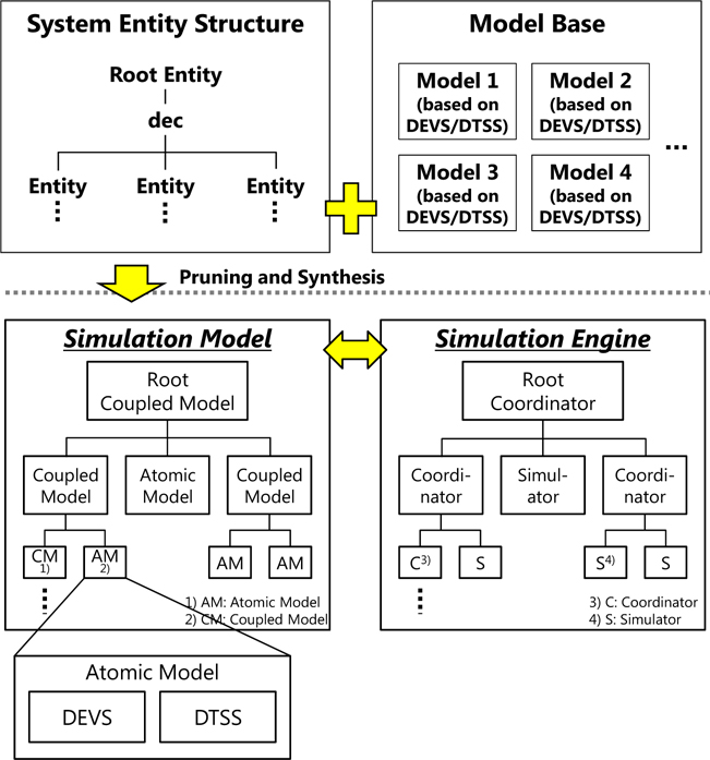
Each system is described by two aspects: its structural (hierarchical) and functional (behavioral) aspects (Dahmani and Hamri, 2011). The SES represents the structural aspect, and the Model Base (MB), the behavioral aspect of the entities in the SES. Let the hierarchical composition structures of the hierarchical and modular models first be extracted from their implementation. Then the structures of a system and the implementation of each subsystem can be saved separately in organized libraries. Fig. 15 shows the concept of the SES and the MB.
The behavioral knowledge of the entities in the MB is modeled based on the DEVS and Discrete Time System Specification (DTSS) formalisms that can handle simulation models of a discrete event and a discrete time (Zeigler et al., 2000). Using these formalisms, a simulation engine can perform a simulation by changing the state of a model according to the events and by calculating the state variables of the model every unit time when the model is in the specific state. These formalisms are widely used as standard formalisms for modeling and simulation. Bang developed a simulation framework based on the combined DEVS/DTSS concepts (Bang, 2006). To evaluate the efficiency and applicability of this simulation framework, Cha et al. (2009) and Ha et al. (2012a; 2012b) applied it to the block erection process in shipbuilding, the dive of a submarine, and an analysis of evacuation of a passenger ship.
>
Creation of a simulation by combining the PES and MB
The PES has relationships among its entities and their hierarchies. The entities in the MB represent their behavioral aspect. By synthesizing the PES and the MB, a model of the whole system that represents all the functions in the system can be made. Fig. 16 shows a male human with two hands generated by the synthesis of the PES and the MB.
As mentioned in Section 4.1, the entities of the SES can have various alternatives on their child entities, and it is represented by the node
If the SES for the liquefaction cycle is configured, the relational models of various alternative liquefaction cycles, which have related equipment, can be automatically generated by pruning the SES. Thus, if the MB is specialized in the purpose of evaluation of the liquefaction cycle considering the design criteria, all the possible alternatives for the FLNG liquefaction cycle can be presented and evaluated by combining the PES and the MB.
ONTOLOGICAL MODELING OF LIQUEFACTION CYCLE USING SYSTEM ENTITY STRUCTURE
The design of liquefaction cycle in the FEED work of FLNG is a procedure for finding the optimal synthesis of the liquefaction cycle given various design criteria. To find the optimal synthesis, various liquefaction cycles should be configured and reviewed vis-a-vis the design criteria. Thus, it is necessary to more simply formulate various configurations of the liquefaction cycles and to easily modify the configurations by adding, rearranging and eliminating equipment until the optimal liquefaction cycle is found. In this chapter, a method based on ontological modeling is proposed for automatic generation of configurations of liquefaction cycles and for their simple modification. The rules for the configuration of the liquefaction cycles were extracted from existing conventional liquefaction cycles that are used in onshore plants, and the configuration of the liquefaction cycles was automatically generated using the SES.
>
General rules for combining equipment units of liquefaction cycle
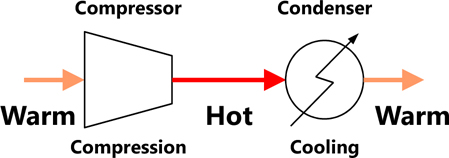
An expert making a flowsheet of the liquefaction process should follow certain rules. For example, after the refrigerant is compressed using the compressor, as shown in Fig. 17, the temperature of the refrigerant from the outlet will depend on the type of process in which the temperature is changed. In adiabatic change, where no change in entropy occurs, the temperature of the refrigerant from the outlet will increase, unlike the temperature of the refrigerant in the inlet. Thus, the condenser may follow the compressor to cool the refrigerant.
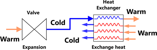
Similarly, after the refrigerant is expanded using an expansion valve, as shown in Fig. 18, the temperature of the refrigerant from the outlet of the expansion valve will be lower in isobaric change, wherein the pressure is constant. Thus, the refrigerant that was cooled after the expansion can be used to cool the warm streams in the heat exchanger.
These rules are based on the experience of the expert, and are the specifications of liquefaction cycles that can be used when the engineer synthesizes a liquefaction cycle. Thus, some rules for synthesizing the liquefaction cycle were extracted from existing onshore liquefaction cycles.
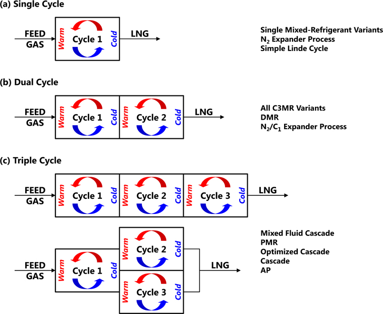
As mentioned in Section 3, the liquefaction cycle can have multiple cooling cycles (Barclay and Shukri, 2000). The number of cycles is a key factor in the success of the liquefaction process. The cycle takes warm pretreated feed gas and cools and condenses it into an LNG product. All modern baseload liquefaction facilities use either two or three cycles, or rarely one cycle. A high-level representation of the number of cycles in various liquefaction processes is shown in Fig. 19.
Each cycle has its own refrigerant. There are two kinds of refrigerants: pure refrigerants and mixed refrigerants. Pure refrigerants like nitrogen and propane are composed of only one material, but mixed refrigerants are combinations of hydrocarbon and nitrogen.
Mixed refrigerants evaporates over a temperature trajectory instead of at a constant evaporating point of pure refrigerants. This refrigeration effect will be distributed over a range of temperatures and accordingly the overall temperature difference between the natural gas and mixed refrigerant is small. This leads to smaller driving temperature differences and gives a more efficient liquefaction process than pure refrigerants.
On the other hand, the foremost advantage of pure refrigerants compared to mixed refrigerants is simplicity. In the cycle using pure refrigerants, the equipment count is low, the configuration is simple and there is no phase change of the refrigerant. Disadvantages include a higher energy demand per produced tons and a large footprint for a large production.
>
Basic stage and additional stages
To cool and condense natural gas, all the cycles should have four basic equipment: a compressor, a condenser, an equipment for expansion (an expansion value or an expander) and a heat exchanger. This combination is called the
To enhance the efficiency of the liquefaction cycle, the engineer can add equipment to it or modify its configuration. There are many types of additional formal stages for enhancing such efficiency, such as
>
Interconnection of liquefaction cycle equipment
To cool the refrigerant and the natural gas, the liquefaction cycle equipment must be interconnected. The liquefaction cycle is extended by interconnection laws, which describe typical physisco-chemical phenomena in liquefaction process systems. In this section, the interconnection laws are extracted from existing conventional liquefaction cycles and categorized based on thermodynamic phenomena such as compression and expansion.
Since a compressor with a large compression capacity is expensive, the combination of smaller-capacity multiple compressors is often used in the liquefaction process system. Compressions can be connected in parallel or in series. If the compressors are placed in parallel, a tee or a phase separator may separate the inlet flow, and a common header may merge the outlet flows from these compressors (see the Niche cycle in Fig. 10). In case of serial connection, a condenser should follow the compressor.
Compression reduces volume. Based on thermodynamics, if there is a change in pressure, the volume and temperature of the material will also change. During compression, the temperature of the refrigerant rises, so a mechanism for decreasing the temperature is needed. To directly cool the temperature, the condenser can be placed next to the compressor. Another option for cooling the temperature is mixing the stream with a lower temperature. Thus, a common header can be placed next to the compressor, and this equipment will cool the temperature by mixing the streams with different temperatures. If there are parallel compression like the Niche cycle, a common header can be also placed next to these compressors to merge multiple flows from the compressors.
The rules related to compression are as follows:a) A condenser can be placed after a compressorb) A common header can be placed after a compressor, but the stream with lower temperature from a heat exchanger or other expander should be joined with the stream from the compressor at the common header.
Even if a material is cooled using a cooling equipment, it cannot be used as a refrigerant because its temperature is higher than the boiling point of natural gas. Thus, the expansion procedure is needed to lower the temperature, which is why the compressor is always placed in front of the condensing equipment. There are two kinds of cooling equipment: a condenser and a heat exchanger. The expansion procedure typically follows the use of the heat exchanger. In contrast, after the refrigerator is cooled using a condenser, another compression procedure using a compressor (see the DMR cycle in Fig. 5) or a heat exchanger (see the N2 dual expander cycle in Fig. 9) can follow. In addition, after the mixed refrigerant is condensed using a condenser, it can have two material phases: the liquid and vapor phases. In that case, a phase separator can be used after the condenser. If the pure refrigerant is used for the cooling cycle, there is no two-phase flow, so a tee can be used instead of a phase separator (see the Niche cycle in Fig. 10).
The rules related to cooling are as follows: a) The expansion equipment can follow the heat exchanger.b) A compressor can be used next if it is necessary to compress the refrigerant.c) A heat exchanger can be used next if a pure refrigerant is needed.d) If the refrigerant is a mixed refrigerant, a phase separator must be used next to separate the flows in the two phases.
>
Equipment after the refrigerant expansion
After the refrigerant is expanded, its temperature is enough to liquefy the natural gas. Thus, the refrigerant from the expansion equipment enters into a heat exchanger, and it will cool the natural gas and warm the refrigerant of the other flows in the heat exchanger.
If the expander is used for the expansion, the expansion work is extracted from the fluid as shaft power and may be used to drive a centrifugal compressor elsewhere in the process. Thus, the expander is connected to the compressor.
The rules related to expansion are as follows: a) The heat exchanger follows the expansion equipment.b) The expander is coupled with the compressor.c) If there is another flow from the heat exchanger, the flows can be merged using the common header.
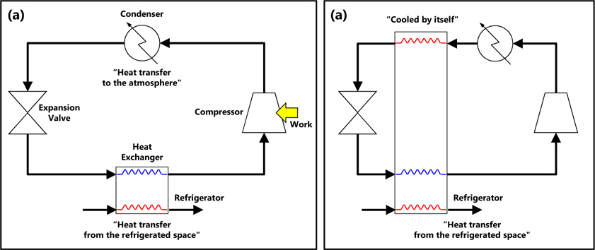
The refrigerant is used to cool not only the natural gas but also the warm refrigerants in the other flows. Regeneration means the refrigerant cools itself in other flows. Thus, in the cooling cycle with regeneration, the refrigerant returns counter-currently through the heat exchanger after it expands, as shown in Fig. 20.
The rule for regeneration is as follows: a) After the expansion, the refrigerant cools itself by flowing through the heat exchanger.
>
System entity structure of liquefaction cycle
Ontology involves explicit specification of a concept. It aims to generally capture consensual knowledge that may be reused and shared by software applications and groups of people. It can be represented with various languages and with different degrees of formality (Morbach et al., 2007). In this paper, the synthesis of the liquefaction cycles was focused on as a small part of ontology in the FEED work of FLNG. The SES was adopted and used to express the ontology for the synthesis of the liquefaction cycles.
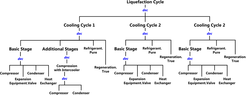
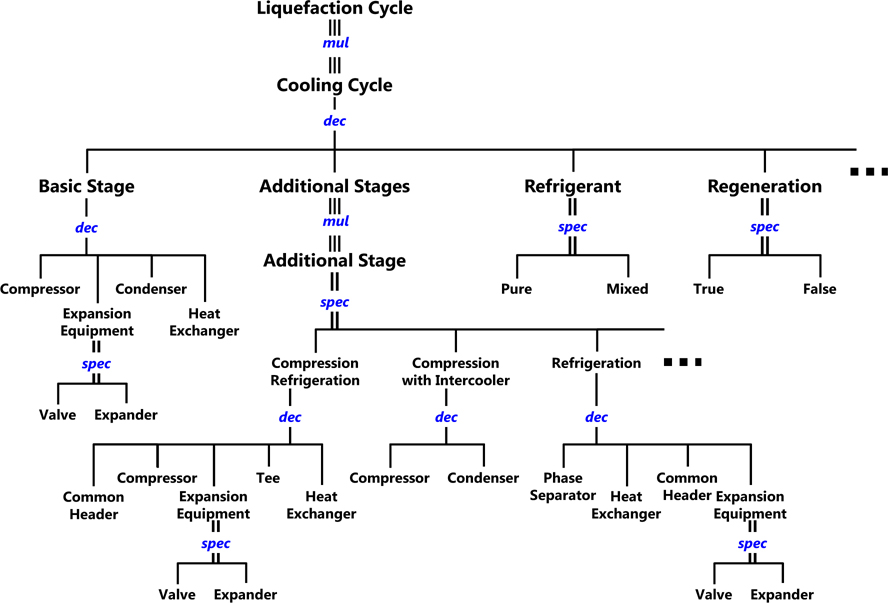
Fig. 21 shows the SES for the liquefaction cycle. As mentioned in the previous section, the liquefaction cycle is decomposed into multiple cooling cycles. The cooling cycle is decomposed into the basic stage, additional stages, the refrigerant, regeneration, and other options (or entities). The refrigerant entity is used to select the refrigerant for each cycle. The regeneration entity is also used to select the usage of regeneration in the basic stage.
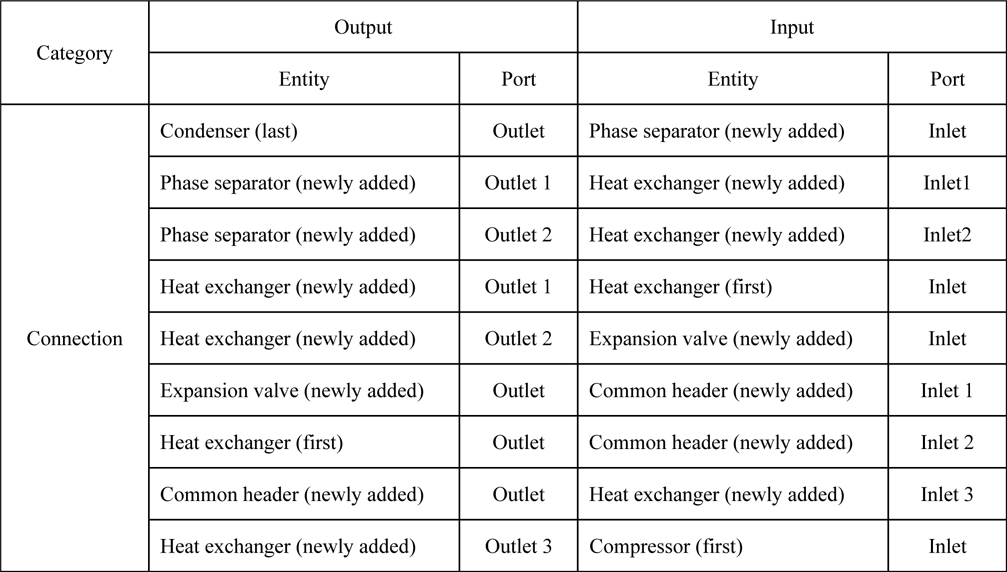
As shown in Fig. 21, the SES has the hierarchical structure of a system or domain. The information on the interconnection of the child entities is stored in the
>
Rules for the basic cycle entity
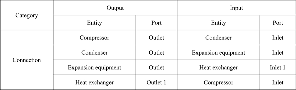
The basic stage is composed of a compressor, an expansion equipment, a condenser, and a heat exchanger. These are interconnected, and the information on their interconnection is defined in the
[Table 1] Rules for interconnecting the child entities of the basic stage entity.

Rules for interconnecting the child entities of the basic stage entity.
In the
[Table 2] Rules for interconnecting entities when the expansion equipment is chosen.
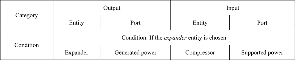
Rules for interconnecting entities when the expansion equipment is chosen.
>
Rules for selecting multiple cooling cycle
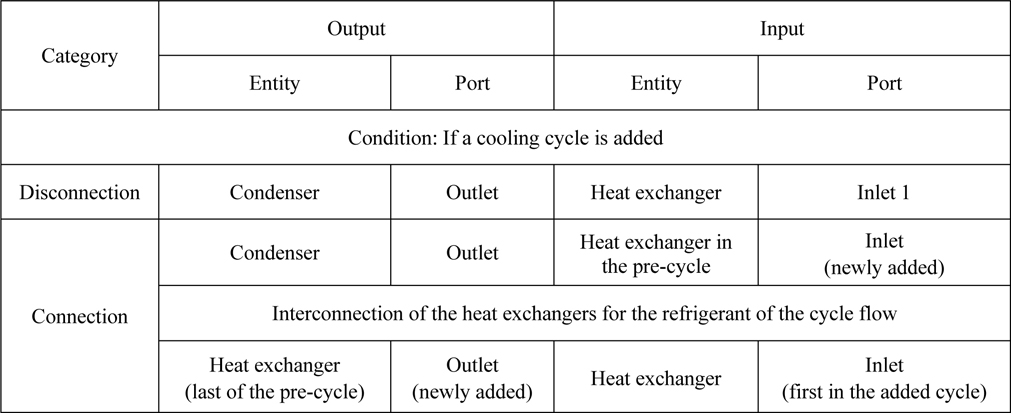
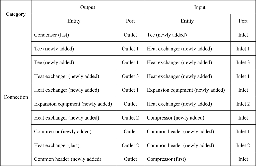
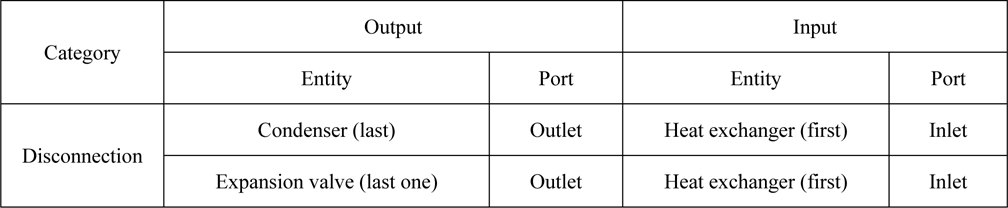
If the cooling cycle is chosen for more than one cycle, the heat exchanger of each cooling cycle, except that of the precooling cycle, should be connected to those of the other cycles. Thus, the compressor and the heat exchanger of the cooling cycle, except that of the precooling cycle, are disconnected, and the connection of the cooling cycles is made in such a way that the refrigerant of the cooling cycle flows to the heat exchanger of the pre-cycle. The pre-cycle is the previous natural-gas cooling cycle. For example, the pre-cycle of the main cooling cycle is the precooling cycle, and the pre-cycle of the subcooling cycle is the main cooling cycle. The rules for interconnecting equipment after selecting multiple cooling cycles are defined in Table 3.
[Table 3] Rules for disconnecting and connecting the equipment of multiple cooling cycles.

Rules for disconnecting and connecting the equipment of multiple cooling cycles.
>
Rules for selecting additional stages
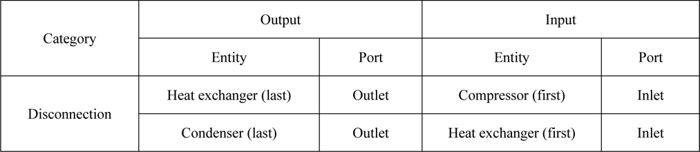
To add an additional stage to the basic stage, the

Rules for disconnecting the equipment of the basic stage entity when additional stage compression refrigeration is chosen.
>
Rules for selecting the compression refrigeration stage
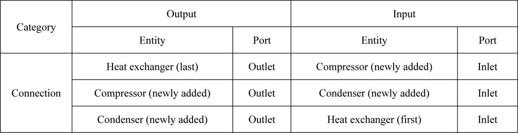
The
Rules for interconnecting the child entities of the compression refrigeration stage entity.
>
Rules for selecting compression with an intercooler stage
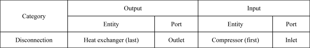
If this additional stage is added, the equipment in the basic stage should be disconnected before being connected with the newly added equipment in the additional stage. Thus, the disconnection rules, according to the choice of compression with an intercooler stage, are defined in the

Rules for disconnecting the equipment of the basic stage entity when the additional stage, compression with an intercooler, is chosen.
The
Rules for interconnecting the child entities of the compression refrigeration stage entity.
>
Rules for selecting the refrigeration stage
To add the additional stage “refrigeration,” the interconnection between the equipment of the basic stage should be disconnected before being connected with the newly added equipment of the additional stage. Thus, the rules for the disconnection according to the choice of the “refrigeration” stage are defined in the
Rules for disconnecting the equipment of the basic stage entity when the additional stage “compression with an intercooler” is chosen.
The
[Table 1] Rules for interconnecting the child entities of the refrigeration stage entity.

Rules for interconnecting the child entities of the refrigeration stage entity.
AUTOMATIC GENERATION OF LIQUEFACTION CYCLE FOR THE FEED OF FLNG BY PRUNING THE PROPOSED SES
The SES contains many alternatives when the selected node is used, such as multiple decomposition and specialization. Thus, by pruning the SES, various alternatives of the liquefaction cycle can be generated automatically.
>
Generation of DMR cycle by pruning the proposed SES
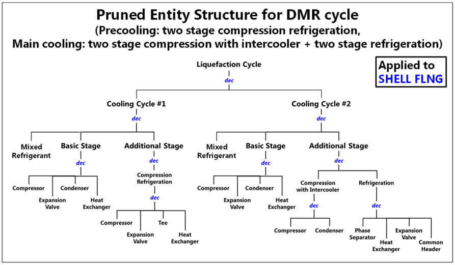
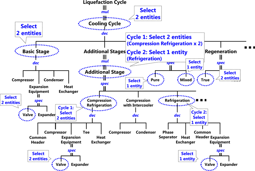
Fig. 22 shows the sequence of the SES pruning for the DMR cycle. The DMR cycle has two cooling cycles: precooling and main cooling. Thus, two entities are chosen at the
Fig. 23 shows the PES for the DMR cycle generated by pruning. PES is a kind of pure entity structure that does not have any selectable node, such as the
Using the PES in Fig. 23, the configuration of the DMR cycle in Fig. 5 can be generated automatically. All the equipment in this configuration are members of the entities in PES, and the equipment are connected with other equipment based on the rules in the nodes of PES.
>
Generation of C3MR cycle by pruning the proposed SES
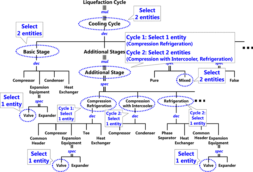
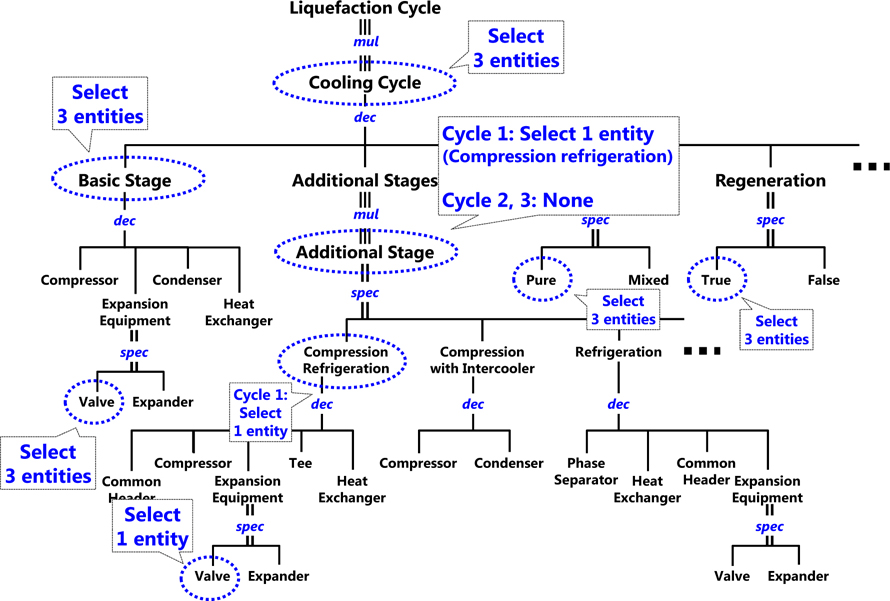
Fig. 24 shows the sequence of the SES pruning for the C3MR cycle. The C3MR cycle has two cooling cycles: precooling and main cooling. Thus, two entities are chosen at the
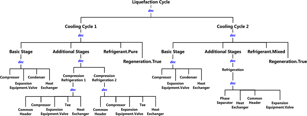
Fig. 25 shows the PES for the C3MR cycle generated by pruning. The PES for the C3MR cycle has two cooling cycles, and each cycle has a
>
Generation of cascade cycle by pruning the proposed SES
Fig. 26 shows the sequence of the SES pruning for the cascade cycle. The cascade cycle has three cooling cycles, and all the cycles use a pure refrigerator. As shown in Fig. 26, the precooling cycle has only one additional stage:
Fig. 27 shows the PES for the cascade cycle generated by pruning. As all the
>
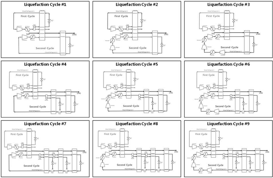
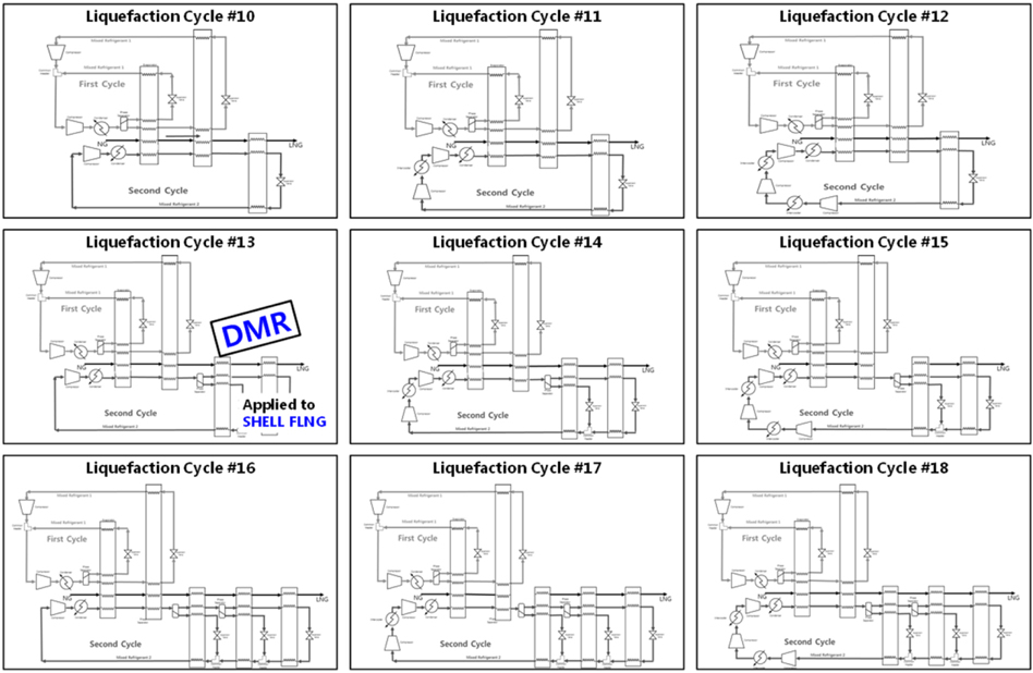
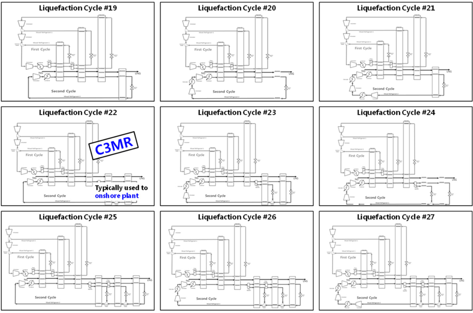
Various alternatives of the liquefaction cycle generated by pruning the proposed SES
Figs. 28~31 show various alternatives of the liquefaction cycle generated by the resultant PES after finishing the pruning process. As mentioned in this section, by pruning the proposed SES, the configuration of liquefaction cycle can be automatically generated, including the conventional liquefaction cycles, such as the DMR, C3MR, cascade, expander, Niche, and other cycles. These configurations can be used for process evaluation, such as process simulation and reliability analysis. Moreover, during the pruning process and the automatic generation of various configurations of the liquefaction cycle, the liquefaction cycles that are not yet under consideration can be generated and evaluated, and they may have new, improved designs of the liquefaction cycle compared with the conventional liquefaction cycles.
>
XML-based configuration of liquefaction cycle for FLNG FEED
One of the key goals of FLNG FEED is analyzing various alternatives and choosing the best one among them. As mentioned in section 6.4, in this study, various liquefaction cycle alternatives were generated by pruning the proposed SES, and they can be used for evaluation purposes according to the design criteria, such as efficiency, simplicity, smaller carbon footprints, higher demand for process safety, and high flexibility. To support such evaluation more conveniently and to interface with other applications, an XML-based liquefaction cycle configuration was provided in accordance with the result of the pruning sequence.
Extensible Markup Language (XML) is a markup language that defines a set of rules for encoding documents in a format that is both human- and machine-readable. Many Application Programming Lnterfaces (APIs) have been developed to aid software developers in processing XML data, and several schema systems exist to aid in the definition of XML-based languages.
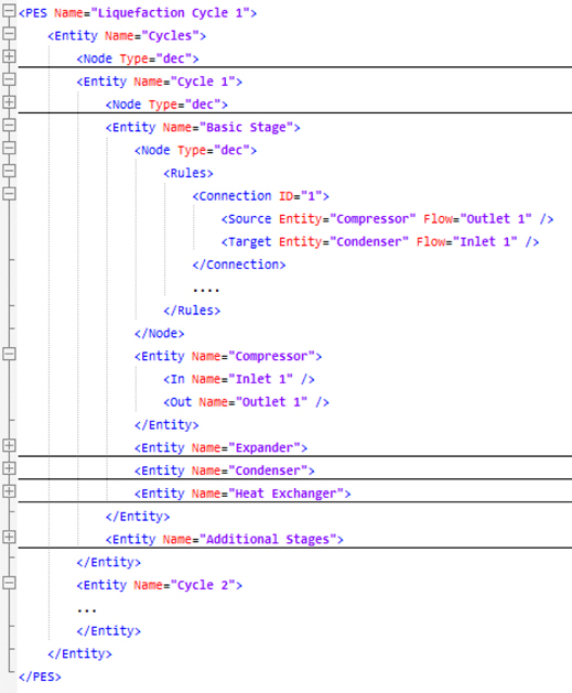
Fig. 32 shows an example of an XML-based liquefaction cycle configuration, which was automatically generated by pruning the SES. As shown in this figure, the main tags of the XML-based configuration are “Entity,” “Node,” “In,” and “Out.” The “Entity” tag matches an entity of the PES. The “Node” tag has a “Type” attribute to identify the type of node below the parent entity. In addition, the “Node” tag has some rules for connection and disconnection, which are defined in the “Connection” and “Disconnection” tags, and they have information on the source and target of the connection or disconnection. The “In” and “Out” tags denote the inlets and outlets of the cycle or equipment. The names of the “In” and “Out” tags are used to configure the connection or disconnection rules.
[Fig. 32] XML-based configuration of liquefaction cycle for C3MR cycle generated by pruning the SES.

In section 6.4, various liquefaction cycle alternatives were generated automatically, and they can also be expressed in the XML-based formats, using the tags mentioned in the previous paragraph. If some APIs for reading this XML-based configuration will be developed, they may be used to evaluate their suitability to certain FLNGs in other applications. For example, they may be converted to the input files of Aspen HYSYS, a commercial software for process simulation, which means that they can be evaluated in terms of efficiency. They may also be applied to PTC Relax, a commercial software for reliability analysis, which means that they can be evaluated in terms of reliability, availability, and maintainability.
This study proposed a modeling technique of FLNG liquefaction cycles using the system entity structure (SES). By pruning the SES, various liquefaction cycle alternatives for FLNG FEED can be generated automatically. The liquefaction cycle configurations can be converted to an XML-based format for interfacing with other applications, for their evaluation and comparison according to the design criteria.
The future work will focus on the use of the proposed method for making various liquefaction cycle alternatives. As mentioned in the previous sections, the proposed XML-based configuration may be used to choose an optimal liquefaction cycle design based on the analysis results. Process simulation is an example of an analysis method for determining the optimal operating conditions of the liquefaction cycle in terms of effectiveness. Reliability is also important for the overall economics of the offshore plant. Thus, these authors are also planning to apply the proposed method to reliability analysis.