검색 전체 메뉴
PDF
맨 위로
OA 학술지
H filter for flexure deformation and lever arm effect compensation in M/S INS integration
  • 비영리 CC BY-NC
ABSTRACT
H filter for flexure deformation and lever arm effect compensation in M/S INS integration
KEYWORD
Integrated system of M/S INS , Flexure deformation , Lever arm effect , Kalman filter , H∞ filter.
  • INTRODUCTION

    On ship, high accurate information from Master Inertial Navigation System (MINS) can be used to fulfill initial alignment for Slave Inertial Navigation System (SINS) composed of low or medium inertial sensors (Titterton and Weston, 2004; Wan and Fang, 1998; Kain and Cloutier, 1989; Shortelle et al., 1998; Grewal et al., 1991). In the integrated system of M/S INS, Kalman filter is often used as an observer, and the differences of velocity, attitude, angular rate and acceleration between MINS and SINS are used as measurement data (Titterton and Weston, 2004; Wan and Fang, 1998).

    In the M/S integration, the acceleration or velocity matching method can achieve its alignment goal in horizontal linear accelerated motion, as the angular rate or attitude matching method can do in horizontal angular motion (Lyou and Lim, 2009; Yu, 1988). A transfer alignment system based on combined matching methods can optimize the Kalman filter to outperform all others in arbitrary motions (Lyou and Lim, 2009; Yu, 1988). The best combined matching scheme is known to be the velocity plus attitude, or angular rate plus acceleration (Lyou and Lim, 2009; Yu, 1988; Wan and Liu, 2005; Xiong et al., 2006; GoshenMeskin and Bar-Itazhack, 1992a; 1992b). Flexure deformation, lever-arm velocity and time-delay are known as major error sources for velocity and attitude matching (Lyou and Lim, 2009; Yu, 1988; Wan and Liu, 2005), as instrument error, noise and time-delay are for angular rate plus acceleration (Yu, 1988; Hu et al., 2005; Huang et al., 2005; Lim and Lyou, 2002).

    Wan and Liu (2005) gave the measurement data about deck flexure deformation of a medium-sized ship at six sea situation. The deformation around y-axis is 0.05~0.08° when it is about ±1.5 m away from the MINS installation position along x-axis, and the deformation around x-axis is 0.17~0.2° when it is about ± 7 m away from the MINS installation position along y-axis. In large ship, increased hull size will inevitably bring increased flexure deformation. The mounted misalignment between SINS and MINS can no longer be regarded as a random constant for such a level deformation (Lyou and Lim, 2009; Wan and Liu, 2005; Lim and Lyou, 2002; Lyou and Lim, 2005). Angular rate matching is a known method for estimating flexure deformation (Wan and Liu, 2005; Hu et al., 2005; Huang et al., 2005). However, this method needs highly precise inertial units, and the MINS and SINS are required to be both strapdown INSs (Wan and Liu, 2005; Hu et al., 2005; Huang et al., 2005). Because platform MINS could not provide angular rates information, derivative errors will be introduced when attitude are used to produce angular rate with differential operation (Titterton and Weston, 2004; Wan and Fang, 1998). The above-mentioned shortcomings limit the wide application of angular rate matching method.

    For a given lever-arm length between MINS and SINS, lever-arm effect can be easily constructed and compensated (Wan and Liu, 2005; Hong et al., 2006). Gao et al. (2009) and Liu (2011) pointed out that, when the longer the lever-arm between MINS and SINS and the severer the flexure deformation of ship deck, the more uncertain of lever-arm length will be introduced. So in large ship, if the length of lever-arm is viewed as a fixed value when lever-arm effect is constructed, large measurement error will be introduced and transfer alignment precision will be decreased. Liu (2011) proposed a method to estimate lever-arm length on-line based on acceleration matching. But this method also requires highly precise inertial units, and the accelerometer outputs are easily suffered by noise due to the interference from sway and oscillation (Yu, 1988).

    On ship, when communication equipment is fixed in a stable environment, time-delay can be regarded as a constant value, which can be easily compensated. With the above assumption, this paper presents a transfer alignment and fusion algorithm based on “velocity plus attitude” to deal with flexure deformation and lever-arm effect. And SINS is assumed as strapdown INS and MINS is as platform INS.

    Lim and Lyou (2002) and Lyou and Lim (2005) introduced H filter to deal with flexure deformation and time-delay. Motivated by these, and considering that attitude matching error caused by flexure deformation and velocity matching error caused by changing of lever-arm size have an upper limit and can be considered as noise with limited energy, this paper takes these errors as uncertain interfering input and introduces them into H filter. By the virtue of the robustness of H filter against uncertain noises, these errors can be effectively restrained. Three filter schemes, standard Kalman filter with known flexure deformation, standard Kalman filter with unknown flexure deformation and H filter with unknown flexure deformation, are compared. Simulation results indicate that the designed H filter can effectively restrain the attitude and velocity matching error caused by flexure deformation and improve the accuracy of SINS.

    The rest of this paper is organized as follows. In Section 2, attitude matching error caused by flexure deformation is analyzed. In Section 3, the change of lever-arm size change caused by flexure deformation and velocity matching error caused by lever-arm change are studied. In Section 4, H filter is designed in detail, system and measurement equations are given. And in Section 5, the effectiveness of the proposed method is verified by simulation. Finally,some conclusions are given in Section 6.

    ATTITUDE MATCHING ERROR CAUSED BY FLEXURE DEFORMATION

      >  Attitude matching algorithm with no flexure deformation

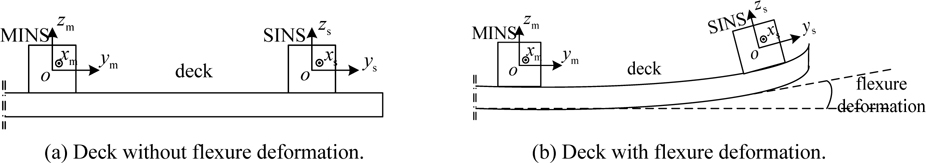
    Ship-based MINS is usually installed at the swing center to measure the overall attitude, velocity and position information, while SINS is usually installed at the head or tail of the ship to measure the attitude and velocity information of the installing position. The schematic diagram of the deck flexure deformation between MINS and SINS is shown in Fig. 1, where m is the MINS body frame, s is the SINS body frame, n is the local horizontal-geographical coordinate frame and navigation frame. In Figs. 1(a) and (b) denote the decks without and with flexure deformation. To a specific ship with limited size, the MINS and SINS have the same navigation frames. is theoretical MINS Direction Cosine Matrix (DCM), and is theoretical SINS DCM. is theoretical DCM between MINS and SINS. When there are no flexure deformation and installing error of SINS, , here “^ ” is a calculated value. In this ideal condition, there exists:

    image

    In engineering, the precision of MINS is usually higher than that of SINS by several orders, and then it can be assumed . In SINS, compared with theoretical DCM , there are an initial alignment error, inertial unit concerned error and calculation error in the calculated DCM . Here we assume the installing error is well compensated, can be expressed as follows:

    image

    where 𝝓 × is skew matrix of misalignment angle of SINS.

    In the attitude matching scheme, the measurement information is the difference between MINS and SINS angles, the measurement matrix can be expressed as follows:

    image

    where vDCM is the measurement noise matrix. Eq. (3a) indicates that the angle difference between MINS and SINS reflects the change of misalignment angle of SINS without flexure deformation. By comparing the difference, the initial alignment error and inertial unit caused error can be estimated. In another word, the attitude matching is the process in which the DCM of SINS is driven to be equal to that of MINS.

      >  Attitude matching algorithm with flexure deformation

    As shown in Fig. 1(b), m' is the flexural body frame and is the flexure deformation matrix between MINS and SINS. is an installing matrix of SINS, and in the case of zero installing error. In the ideal condition, there exists:

    image

    If the flexure deformation angle is defined as 𝜽 , there is . In calculation, there exists:

    image

    By comparing Eqs. (3) and (5), it can be concluded that, the MINS and SINS angle difference includes the flexure deformation and cannot reflect the change of SINS misalignment angle. In this circumstance, if the DCM of SINS is also driven to be equal to that of MINS, cannot represent the attitude change of SINS installing position, and the navigation function of SINS will not work. When this flexure deformation exists, the real measurement matrix is as follows:

    image

    where is the measurement noise matrix. When there is an upper limit of flexure deformation, is color noise with limited energy.

    VELOCITY MATCHING ERROR CAUSED BY FLEXURE DEFORMATION

      >  Lever-arm velocity calculation between MINS and SINS

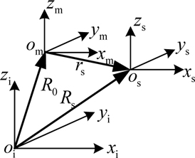
    The installation relationship between MINS and SINS is shown in Fig. 2, where i is inertial frame; R0 and Rs are the position vector of MINS and SINS in the inertial frame; rs is the position vector of SINS relative to MINS in MINS body frame, i.e. lever-arm vector, respectively. There exists:

    image

    In Fig. 2, based on Newtonian mechanics, when the ship rotates relatively to the inertial frames with the angular rate , the relative velocity and acceleration between MINS and SINS can be expressed as follows:

    image
    image

    In Eq. (8), the last four elements are defined as lever-arm effect, which are caused by the difference of installing position between two measurement units. With Eq. (8), lever-arm effect can be constructed by and rs .

    Traditionally, lever-arm effect is a harmful element, and must be eliminated from acceleration (Kain and Cloutier, 1989; Shortelle et al., 1998; Grewal et al., 1991; Lyou and Lim, 2009; Yu, 1988). However, on large ship, long lever-arm and ship swing would generate a non-ignorable lever-arm velocity at the installing position of SINS. In this case, lever-arm effect in Eq. (8) cannot be eliminated and must be solved as valid measurement information. In order to improve the solving accuracy of pitch and roll and velocity of SINS, especially to restrain the upward velocity divergence, velocity matching is introduced. Pseudo-velocity of MINS in the installing position of SINS can be built by the velocity of MINS and lever-arm velocity.

    From Eq. (7), the velocity difference between MINS and SINS can be expressed as follows:

    image

    where ΔV is defined as lever-arm velocity. In the ideal condition, there exists:

    image

    where Vm and Vs are the MINS and SINS velocity in navigation frame respectively.

    With no changing in lever-arm size, Eq. (10a) can be rewritten as follows:

    image

    In the velocity matching method, the velocity measurement information is as follows:

    image

    where vV are measurement noise. In the equation above, is the pseudo-velocity of MINS in the installing position of SINS. And ZV indicate the solving error caused by misalignment angle and unit error.

      >  Lever-arm velocity error caused by flexure deformation

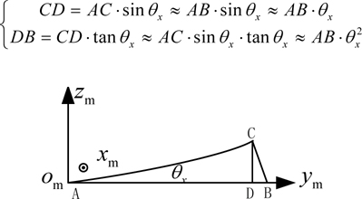
    Taking the flexure deformation around x-axis as an example, the lever-arm change caused by flexure deformation is shown in Fig. 3. In this figure, AB is the projection of the lever-arm in y-axis in body coordination, θx is the body flexure deformation around x-axis (this is micro-angle), and AC is the deformation of AB due to body flexure deformation, respectively. From Fig. 3, it can be seen clearly that flexure deformation brings the projection change CD in z-axis, and the projection AB in y-axis changes to AD . The relationships among the above values are as follows:

    Similarly, the lever-arm projections in other axes and the lever-arm changes caused by deformation around other axes can be analyzed. If θ = [θx θy θz]T is defined as flexure deformation around three axes, and rs = [rx ry rz]T is defined as named lever-arm which can be calculated by the relative position between MINS and SINS when there is no ship body flexure deformation, the real lever-arm is as follows:

    image

    Eq. (12) indicates that lever-arm size is the function of flexure deformation angle. When there is flexure deformation, in Eq. (10a) is not equal to zero, and the velocity difference in (11a) includes the velocity changes caused by lever-arm changes. If these changes are ignored, estimated errors in misalignment angle and unit error will be produced. So in engineering, there exists:

    image

    where is measurement noise. When there is an upper limit of flexure deformation, is color noise with limited energy.

    DESIGN OF H FILTER

      >  SINS error equations

    System’s state equation and measurement equation are as follows:

    image

    where XkRn×1 is system’s state vector; n and k are the dimension of state vector and the update step respectively. Fk,k−1Rn×n is the system’s transfer matrix, WkRn×1 represents system’s process noise and Γk ,k−1 is the noise matrix, ZkRm×1 is system’s measurement vector and m is the dimension of measurement vector respectively, HkRm×n and VkRm×1 are system’s measurement matrix and measurement noise respectively.

    System’s state vector can be described as follows:

    image

    where δVE~N are east and north and up velocity error respectively; ϕx~z are east and north and up misalignment angle respectively; δλδLδh represent longitude and latitude and height error; εx~z are gyro null drift around x, y and z direction respectively; ∇x~z are accelerometer null bias along x, y and z direction.

      >  Velocity error equation can be expressed as follows:

    image

    where fn is the measured value of accelerometer; are angular velocity of earth-fixed frame relative to inertial frame; are angular velocity of navigation frame relative to earth-fixed frame; superscript n denotes the projection in navigation frame; “ ⋅ ” represents differential calculus.

    Misalignment angle error can be calculated as follows:

    image

    where are angular velocity of navigation frame relative to inertial frame respectively.

    Position error equations are as follows:

    image

    where R is the earth’s radius.

    Gyro drift and accelerometer bias are first-order Markov process and can be expressed as follows:

    image

    where is the DCM, and in SINS is .

    System’s transfer matrix Fk ,k −1 can be calculated from Eqs. (15) to (18). System’s process noise is a zero-mean white noise sequence with variance matrix Qk .

    The “attitude plus velocity” matching method, i.e. taking the difference value of angle and velocity between and SINS as system’s measurement vector, is adopted in the integrated system. There exists:

    image

    System’s measurement matrix is as follows:

    image

    If the statistics of Wk and Vk is known, state vectors can be estimated by standard Kalman filter. But from the analysis in section 1.2 and 2.2, it can be known that there are unknown flexure deformation value in Zϕ and unknown lever-arm velocity change in ZV . By subsuming the above elements in measurement noise, it can be concluded that system’s measurement noise Vk becomes uncertain noise with limited energy as showed in Eqs. (3b) and (11b). So with “attitude plus velocity” matching method, SINS state vector errors cannot be estimated with standard Kalman filter, when there is non-ignorable flexure deformation between MINS and SINS.

      >  H sub-optimal filtering equation

    H filter is a robust filter based on the Standard Kalman iterative structure. In H filter, measured value Zk is used to estimate any linear combination with the following state:

    image

    where YkRq×1 is any linear combination and q is the dimension of the combination, LkR q×n is a given matrix. In the case of estimating the state vector directly, Lk is an eye matrix with the dimension of n×n .

    image
    image

    Supposing that Tk(Ff) is the transfer function from the unknown interference to filtering error {ek}, the H sub-optimal filtering problem can be described as follows. For a given constant γ > 0 , one should seek the H sub-optimal estimate strategy to satisfy ║Tk(Ff)║ <γ, i.e. seek a sub-optimal estimate strategy in order to satisfy the following equation:

    image

    where X0 and are the true value and estimated value of state vector at initial moment respectively; P0 is the estimated error matrix of state vector at initial moment.

    For Eq. (23), the necessary and sufficient condition for solving the H sub-optimal filtering problem is as follows:

    image

    where Pk and Hk are the estimated error matrix of state vector and measurement matrix at moment k . When the statistical characteristic of system noise Wk is known as zero mean white noise, measurement noise is Vk unknown and system state Xk is to be estimated directly, H sub-optimal filtering recursive equation can be expressed as follows:

    image
    image
    image
    image

    where Rk and are the estimated variance matrix of measurement noise and estimated value of state vector at moment k , and Kk+1 is the gain matrix at moment k +1.

    SIMULATION

      >  Simulation schemes

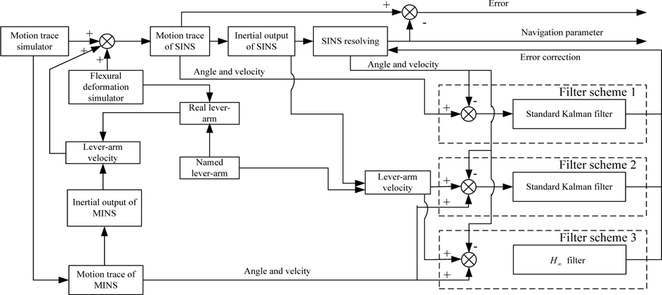
    Ship swinging and translational motions are produced by motion trace simulator, and these motions are used as angle and velocity output by MINS.

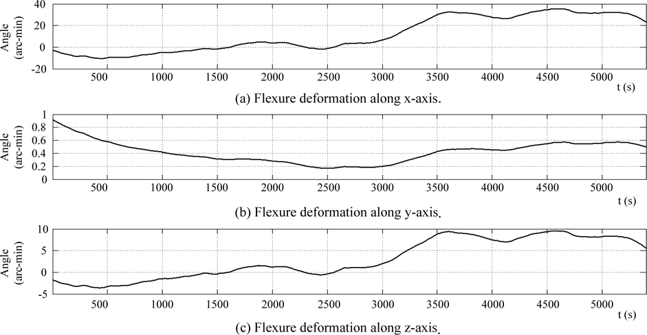
    Second-order Markov process is used to produce ship body flexure deformation and the flexure deformation angle added MINS angle are used as ideal angle output of SINS. Named lever-arm and flexure deformation angle are used to produce real lever-arm. Then lever-arm velocity can be calculated by real-lever arm size and angular rate of MINS. Lever-arm velocity added the velocity of MINS is used as ideal velocity output by SINS. The ideal inertial unit output of SINS can be calculated by these ideal outputs of SINS with back-stepping navigation solution, and these ideal inertial unit output added white noise are used as the real inertial unit output. With these inertial outputs, SINS solving can be carried, the accuracy of solution and the following filters can be evaluated by comparing these solving output with the ideal output.

    Three simulation schemes are established, which are known flexure deformation and the standard Kalman filter, unknown flexure deformation and standard Kalman filter and unknown flexure deformation and H filter, respectively. In the first scheme, ideal SINS angle output are used as angle observation. And lever-arm velocity is built by real lever-arm and ideal MINS angular rate, lever-arm velocity added MINS velocity are used as velocity observation. In the second and third schemes, ideal MINS angle outputs are used as angle observation. And lever-arm velocity is built by named lever-arm and the MINS angular rate, lever-arm velocity added MINS velocity are used as velocity observation.

    Detailed simulation and filter schemes are shown in Fig. 4.

      >  Simulation settings

    In the simulation, the ship is assumed to be sailing 45° north by east at the speed of 5 m/s uniformly. The pitch, roll and yaw oscillation magnitude are 5° and 8° and 3° respectively, and their periods are 20 sec. and 10 sec. and 15 sec. respectively. The SINS is composed of inertial units with medium accuracy, the constant and random drift of gyro are both 0.05 °/h and that of the accelerometer are both 50×10-6 g. The mean square deviation of angle and velocity observation are 0.3° and 0.4 m/s, respectively.

    The named lever-arm sizes between MINS and SINS along x~z axes direction are 10 m, 100 m, and 20 m, respectively. The mean square deviation σ of flexure deformation around x~z axes are assumed to be 30' and 0.5' and 8' , respectively, and correlative time constant τ are 2000 sec. and 3000 sec. and 1800 sec., respectively. The body flexure deformation angle is shown in Fig. 5.

      >  Results and analysis

    The simulation lasts 5,400 sec. The results are shown in Figs. 6 and 7. In these figures, solid lines and dot-dashed lines and dashed lines denote the error curves of scheme1 and 2 and 3, respectively. Data of the stable filtering part from 1500 sec. to 5400 sec. is extracted for analyzing and the results are shown in Table 1.

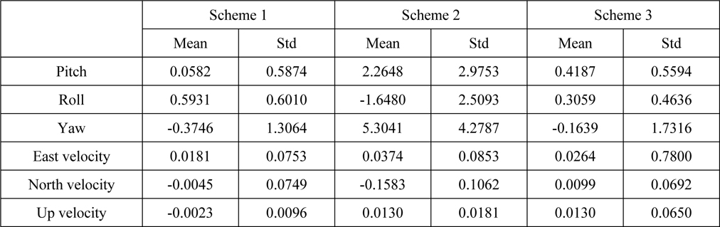
    [Table 1] Statistic of error (unit: angle (arc-min) and velocity (m/s)).

    label

    Statistic of error (unit: angle (arc-min) and velocity (m/s)).

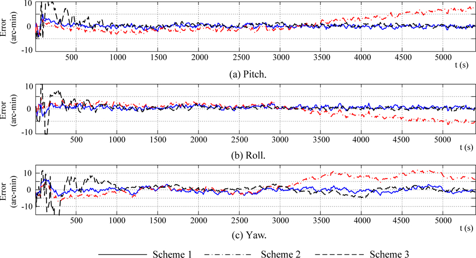
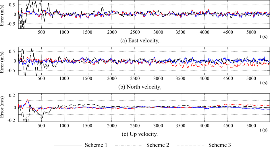
    In Figs. 6 and 7, results from solid lines indicate that the effect of standard Kalman filter is excellent when the flexure deformation is well known. In this condition, the impact to angle and velocity matching information caused by flexure deformation can be well compensated.

    In Figs. 6 and 7, results from dash lines indicate that when there is non-ignorable flexure deformation, the “attitude plus velocity” with standard Kalman filter cannot estimate the misalignment angle and other error caused by unit error. Generally, if the measured velocity is accurate, velocity matching method can estimate the horizontal misalignment angles. But because of the error in velocity measurement caused by flexure deformation, the curve in Fig. 6(2) with Scheme 2 cannot converge. When ship sailing 45°north by east, flexure deformation around x-axis is projected into east and north, the east and north lever-arm velocity error are brought in, and the horizontal misalignment is caused by the lever-arm velocity errors. So in the east-north-up frame, pitch and roll errors have the same and contrary trend with the flexure deformation around x-axis. When sailing in a constant direction, the yaw error is mainly directed by yaw angle observation. In Fig. 6(3), yaw error curve has the same trend and same magnitude as the flexure deformation with z-axis. Fig. 7 and velocity statistic in Tab.1 show that velocity error all effected by flexure deformation.

    In Figs. 6 and 7, result froms dot-and-dash lines show that attitude and velocity error curve slowly converge around zeroes with small oscillation after relatively strong shock at the initial filter period. After about 1000s, the trends of dot-and-dash line coincide with that of solid line, but vibration amplitude is stronger than that of solid line.

    The statistics in Table 1 also verifies the above analysis. From the Figs. 6 and 7 and Table 1, it can be concluded that angle and velocity accuracy can be effectively improved by H filter when “attitude plus velocity” matching method is adopted and flexure deformation is unknown but non-ignorable.

    CONCLUSION

    On ship, especially on large ship, flexure deformation and lever-arm effect are the key factors which decide the actual accuracy of integrated system of M/S INS. Attitude and velocity matching errors caused by deformation is analyzed and simulation results indicate that with “attitude plus velocity”, effective combination of M/S INS cannot be fulfilled. To solve this problem, the H filter is introduced, in this filter attitude matching errors and velocity errors are attributed as noise with limited energy. In this way, the effect of flexure deformation is restrained by the robustness of H filter. Simulations with three schemes are performed. The results indicate that in the ship-based M/S INS integrated navigation system, when angle and lever-arm velocity error caused by flexure deformation cannot be measured but is non-ignorable, the accuracy and robustness of the integrated system can be improved by using H filter.

참고문헌
  • 1. Gao Q.W., Zhao G.R., Wang X.B. 2009 Transfer alignment error compensator design for flexure and lever-arm effect [4th IEEE Conference on Industrial Electronics and Applications] P.1819-1822 google
  • 2. Goshen-Meskin D., Bar-Itazhack I.Y. 1992 Observability analysis of piece-wise constant systems. Part I: Theory [IEEE Transaction on Aerospace and Electronic Systems] Vol.28 P.1056-1067 google
  • 3. Goshen-Meskin D., Bar-Itazhack I.Y. 1992 Observability analysis of piece-wise constant system. Part II: Application to inertial navigation in-flight alignment [IEEE Transactions on Aerospace and Electronic Systems] Vol.28 P.1068-1075 google
  • 4. Grewal M.S., Henerson V.D., Miyasako R.S. 1991 Application of Kalman filtering to the calibration and alignment of inertial navigation systems [IEEE Transactions on Automatic Control] Vol.36 P.3-13 google
  • 5. Hu J., Zhou B.L., Cheng X.H. 2005 Comparison on two methods of transfer alignment with carrier flexure [Chinese Inertial Technology Transaction] Vol.13 P.15-18 google
  • 6. Huang K., Shan F.L., Yang G.L. 2005 Angular rate matching method for shipboard transfer alignment [Journal of Chinese Inertial Technology] Vol.13 P.1-5 google
  • 7. Hong S., Lee M.H., Chun H.H., Kwon S.H., Speyer J.L. 2006 Experimental study on the estimation of lever arm in GPS/INS [IEEE Transaction on Vehicular Technology] Vol.55 P.431-448 google
  • 8. Lim Y.C., Lyou J. 2002 Transfer alignment error compensator design using H∞ filter [Proceedings of the American Control Conference] P.1460-1465 google
  • 9. Liu C., Deng Z.H., Gao W.S. 2011 Estimate dynamic lever-arm caused by ship flexure deformation based on acceleration matching [2011 30th Chinese Control Conference] P.1476-1481 google
  • 10. Lyou J., Lim Y.C. 2005 Transfer alignment error compensator design based on robust state estimation [Transactions of the Japan Society for Aeronautical and Space Sciences] Vol.48 P.143-151 google
  • 11. Lyou J., Lim Y.C. 2009 Transfer alignment considering measurement time delay and ship body flexure [Journal of Mechanical Science and Technology] Vol.23 P.195-203 google
  • 12. Kain J.E., Cloutier J.R. 1989 Rapid transfer alignment for tactical weapon application [AIAA Guidance, Navigation and Control Conference] P.1290-1330 google
  • 13. Shortelle K.J., Graham W.R., Rabourn C. 1998 F-16 flight tests of a rapid transfer alignment procedure [IEEE Conference on Position Location and Navigation Symposium] P.379-386 google
  • 14. Titterton D.H., Weston J.L. 2004 Strapdown inertial navigation technology google
  • 15. Wan D.J., Fang J.C. 1998 Initial alignment of inertial navigation google
  • 16. Wan D.J., Liu Y.F. 2005 Summary on removing influence of ship deformation and providing accurate attitude reference for warship [Journal of Chinese Inertial Technology] Vol.13 P.77-83 google
  • 17. Xiong Z.L., Sun F., Nie Q. 2006 Observability analysis of INS rapid transfer alignment [Proceeding of 6th World Congress on Intelligent Control and Automation] P.1664-1668 google
  • 18. Yu J.X. 1988 A study of transfer alignment methods of INS [Acta Aeronautica ET Astronatuica SINCA] Vol.9 P.211-217 google
OAK XML 통계
이미지 / 테이블
  • [ Fig. 1 ]  Schematic diagram of deck deformation between MINS and SINS.
    Schematic diagram of deck deformation between MINS and SINS.
  • [ ] 
  • [ ] 
  • [ ] 
  • [ ] 
  • [ ] 
  • [ ] 
  • [ ] 
  • [ Fig. 2 ]  Installation sites of ship-based MINS and SINS.
    Installation sites of ship-based MINS and SINS.
  • [ ] 
  • [ ] 
  • [ ] 
  • [ ] 
  • [ ] 
  • [ ] 
  • [ Fig. 3 ]  Change of lever-arm size caused by flexure deformation.
    Change of lever-arm size caused by flexure deformation.
  • [ ] 
  • [ ] 
  • [ ] 
  • [ ] 
  • [ ] 
  • [ ] 
  • [ ] 
  • [ ] 
  • [ ] 
  • [ ] 
  • [ ] 
  • [ ] 
  • [ ] 
  • [ ] 
  • [ ] 
  • [ ] 
  • [ ] 
  • [ ] 
  • [ ] 
  • [ Fig. 4 ]  Simulation and filter schemes.
    Simulation and filter schemes.
  • [ Fig. 5 ]  Ship body flexure deformation angle.
    Ship body flexure deformation angle.
  • [ Fig. 6 ]  Curve of attitude error.
    Curve of attitude error.
  • [ Fig. 7 ]  Curve of velocity error.
    Curve of velocity error.
  • [ Table 1 ]  Statistic of error (unit: angle (arc-min) and velocity (m/s)).
    Statistic of error (unit: angle (arc-min) and velocity (m/s)).
(우)06579 서울시 서초구 반포대로 201(반포동)
Tel. 02-537-6389 | Fax. 02-590-0571 | 문의 : oak2014@korea.kr
Copyright(c) National Library of Korea. All rights reserved.