A marine propeller operates in the complex flow field called the ship’s wake and the transition of flow angle of attack leads to rapid changes in pressure distribution on the propeller blade. As the trend of high power engines follows increases in vessel size, a marine propeller is being exposed to various risks including cavitation erosion, pressure fluctuation-induced vibration, underwater radiation noise, etc.
Compared with propellers made of metal, those made of composite materials - a combination of two or more physically / chemically heterogeneous materials - have superior properties for managing these risks. Composite materials are light weight, and have high stiffness and better sound absorption ability (ITTC, 2005). Despite their higher costs, the excellent manufacturing and maintenance ability of an additive production process is expanding the application of composite materials to all industrial areas, including aviation, environment/energy, information, electricity, automobile and household supplies.
Attempts are being made to use composite materials in the marine propeller blades of warships, submarines, and torpedoes for two reasons. First, composites can improve chance of survival because their good sound absorption ability reduces noncevitating propeller noise. Second, their blade deformation characteristics of the wake distribution delays cavitation inception and reduces cavitation volume. Their superior properties have led to their expanded application in yachts, tugs, and fishing boats. Composite materials also make it possible to reduce A/S costs for preventing heat damages in shaft systems, and to simplify the vessel stern structures due to their light weight - less than half the weight of Nickel-Aluminum-Bronze (NAB) alloy (ITTC, 2005).
The amount and geometry of a composite material’s deformation from the acting load can be controlled with different combinations of laminated material, stacking order, and ply angle. Thus, if its deformable characteristics can be properly considered at the design stage, a composite propeller can reduce fuel oil consumption in its operating profile compared with an NAB propeller which does not change shape (Young, 2007a; 2007b; 2008).
While recognizing these virtues, the difficulty is that it is not easy to accurately and practically simulate the hydro-elastic behavior of the composite marine propellers. These simulation difficulties act as a barrier to the accurate prediction of propulsion performance, initial geometry decisions, and strength evaluations at the propeller design stage.
Inviscid numerical methodologies for calculating the flow field around propeller blades include the lifting line method, the lifting surface method (or vortex-lattice method, VLM), and the boundary element method (BEM). These inviscid methods are widely used in propeller performance prediction because of their short computing times and general usability. Computational fluid dynamics (CFD) analyses (RANS, LES, etc.) that consider the viscous effect tend to use a propeller flow analysis, which requires increased computing power. Even though the viscous flow analyses give a more accurate solution, BEM-based FSI analysis is performed in this study due to the considerations of computing time for the evaluation of propeller design applications.
The lifting line theory, proposed by Prandtl (1921), and the VLM, which was applied to the propeller by Kerwin et al. (1978), are useful methods for initial propeller design due to their ease of calculation. They have limitations, however, when considering three-dimensional blade geometry, BEM is introduced to achieve a more accurate FSI analysis. BEM, also called the panel method, was adapted to the propeller by dividing the potential basis and velocity basis methods of Hess and Valarezo (1985), Lee (1987), Kerwin et al. (1987), Hoshino (1989), etc. After Lee (1987) showed the excellent performance of the potential basis method, this method has been mainly used in the field of propeller analysis. Hsin (1990) and Suh et al. (1992) proposed the Kutta condition and Greeley and Kerwin (1982) and Lee (1987) introduced the flow-adapted grid to include a propeller wake roll-up model for improved convergence in the BEM analysis. These methods apply to the BEM code, KPA14, used in this study.
Various other numerical and experimental studies have also been conducted to analyze composite material (or elastomer) propellers. Lin and Lin (1996) simulated the elastic behavior of marine propellers in noncavitating conditions with a VLMFEM interaction. Young (2007a; 2008) showed a hydro-elastic response of a composite propeller in steady/unsteady conditions by using BEM-FEM FSI and validated the results with model test results. In particular, Young’s study conducted BEM analysis to predict the hydrodynamic damping effect for unsteady behavior such as blade “fluttering” induced by a change in inflow conditions at the hull behind the wake field. Chen et al. (2006) evaluated the behavior of the composite marine propeller in four-cycle inflow conditions by performing model tests and a numerical simulation. Motley et al. (2009) and Blasques et al. (2010) studied optimum material stacking to improve propulsion efficiency and Jang et al. (2012) proposed a reverse engineering procedure for the initial design of an elastomer propeller considering blade deformation. Lee et al. (2009), Lee et al. (2012) and Lee et al. (2013) have carried out the study of the relationship between manufacturing and performance of flexible (composite) propeller.
The hydro-elastic analysis of a flexible marine propeller, which is a simplified orthotropic-homogeneous material model of a composite propeller, has been developed to accurately and efficiently predict the propeller’s propulsion performance and evaluate its strength. For practical use in the propeller design stage, the inviscid potential-based BEM code, KPA14, is used to calculate the loads on the blades. A commercial Finite Element Analysis (FEA) solver (Abaqus Standard) is introduced for predicting blade deformation and evaluating propeller strength. An interface between these two solvers is developed to analyze the hydro-elastic behavior of the composite-material propeller, and the accuracy and usability of the developed algorithm are confirmed by comparing our results with the model test results in previously published literature.
FORMULATION AND NUMERICAL METHODS
The flow field around the propeller blade, the structural deformation, and their relationship at the blade surface are numerically formulated for the FSI analysis to predict the performance of the marine propeller.
>
Governing equation of the flow field around the propeller blades
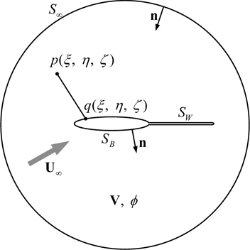
As mentioned in the previous section, the potential basis analysis, from the studies of Hsin (1990), Suh et al. (1992), Greeley and Kerwin (1982) and Lee (1987), are applied to analyze the steady or unsteady flow fields. We assume that the flow field consists of the three-dimensional closed boundary
The perturbed velocity potential

When applying the boundary condition to the boundaries, the boundary value problem can be formulated and the kinematic boundary condition must be satisfied on the propeller blade surface

Assume that wake surface

The Kutta condition of Eq. (4) is applied to the unique circulation at the trailing edge of the blades.

Namely, the flow velocity is finite at the trailing edge and at the outer boundary, the perturbed velocity induced by the propeller is vanishing far away from the blade surface as follows:

The disturbed velocity potential

where S∞ : Sblade + Shub p : point induced velocity potential is calculated q : point positioned singularity R( p; q) : distance between p and q
The geometry of the propeller blades, hub, and wake could be discretized as a panel to numerically solve the governing equation in Eq. (7).

The effective coefficients
To solve the unsteady transient flow problem defined by the time domain, a steady analysis for the key blade is performed for every time step and the singularity of the other blades is updated for every step shown in Eq. (8).

where and variable
The pressure acting on the blade surface can be obtained by using the velocity potential derived from the discretized integral equation in Eqs. (7) or (8) as follows:

where the operator ∂ / ∂
>
Structural equations of motion for blade deformation
The equation of motion for the structural deformation corresponding to the propeller blade fixed coordinate is as Eq. (10),

where Ms is the mass matrix, Cs is the damping matrix, Ks is the stiffness matrix which represents the material mass, damping and stiffness of the composite propeller blade. The values of mass, damping and stiffness in the validation have use of published experimental results. , , d are acceleration, velocity, and displacement for the computing point, respectively.
FST in Eq. (11) represents the total of all loads acting on the blade structure. These consist of the hydrodynamic pressure load Fhp and the body force due to rigid body rotation, the Coriolis force Fcori and the centrifugal force Fcent, and the coupling component force Ffs acting on the interface between the fluid and the structure. The summation of the structural loads except Ffs can be written as Fs .

The structural analysis of the hydro-elastic response is conducted with the commercial FEA solver Abaqus 6.12. Since the implicit method is adapted for both the steady and unsteady analyses, the static option of the Abaqus Standard is used for the steady state analysis and the dynamic option is used for the transient analysis.
The Newmark integration method of Eqs. (12) and (13) is applied to solve the nonlinear dynamic response problem and the model response at time


where parameters
The 8-node continuum shell element is used in the structural analysis. This element can reflect the three-dimensional geometry of the propeller blade and has the merit of giving a shell element to the plate-like structure, as well as having automatic mesh generation and ease in applying the material properties according to the ply.
Assuming that deformation of the blade for the inflow variation is relatively large and that the change in the hydrodynamic characteristics due to geometrical alteration is not small, the FSI effect must be applied for the estimation on each hydrodynamic force and structural deformation. We propose using a two-way coupled FSI analysis that includes structural nonlinear analysis because the amount of blade deformation is not small to assume linear according to Young (2008). To analyze strictly for the elastically vibrating response due to the changing flow field in the ship’s wake, the “wet” condition (considering not only hydrodynamic pressure distribution on blade but including hydrodynamic added mass/damping effect) must be considered. The acoustic fluid medium finite element model is adapted to consider this effect. This acoustic medium model was applied to ship hull vibration in contact with water by Paik (2010).
Let the fluid field around propeller blade be compressible and inviscid then the equation of equilibrium is as follows:

where
Fluid volumetric strain can be represented as in Eq. (15) by the definition of the relationship between the bulk modulus and pressure.

The equation of motion for hydro pressure can be derived from Eqs. (14) and (15).

The equation of motion that considers the coupling of the boundary between the fluid and the structure can be expressed as the vector form.

where Mf, Cf, Kf and Sfs are 1 /


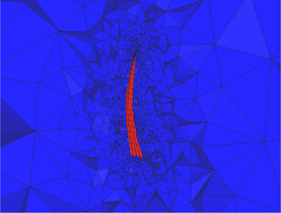
The tetra mesh (AC3D4 known as an element type of Abaqus Standard) of the acoustic medium domain is composed to perform structural analysis with consideration to the hydrodynamic damping due to added mass are shown in Fig. 3.
METHODOLOGY FOR HYDRO-ELASTICTY ANALYSIS OF A PROPELLER BLADE
Based on the formulated mathematical model, we implement a steady and unsteady transient FSI algorithm to predict the performance and evaluate the structure of the flexible propeller.
>
Basic concept of FSI analysis
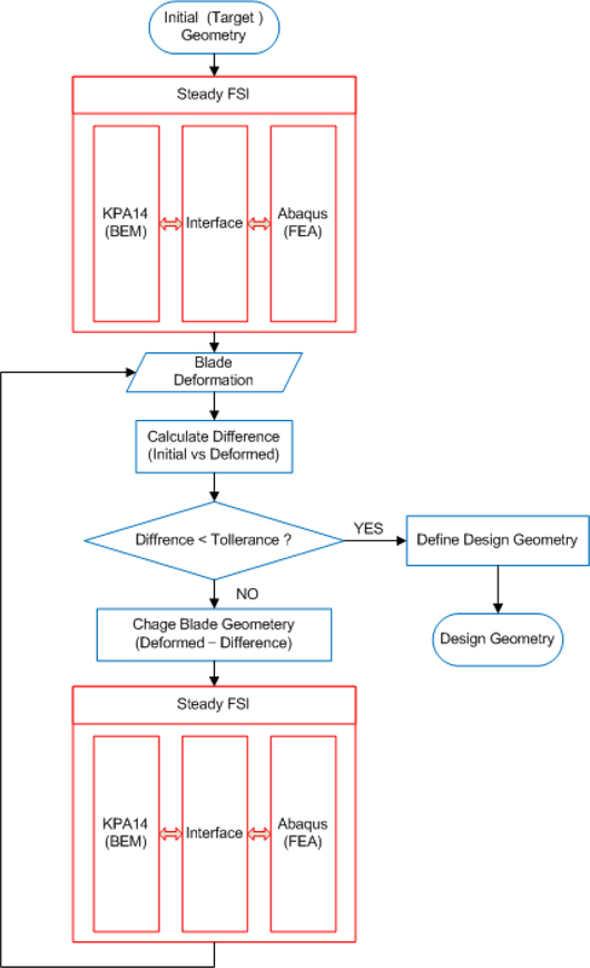
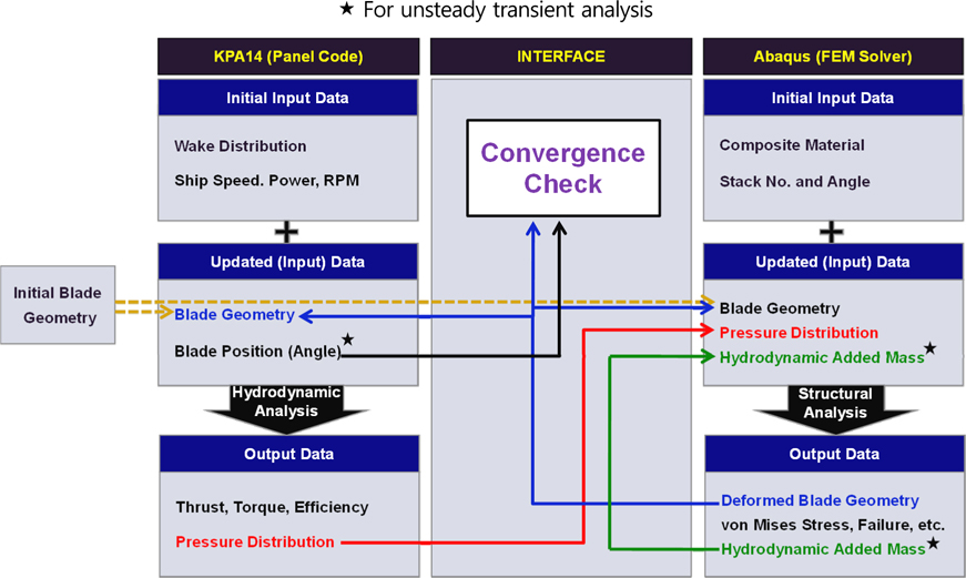
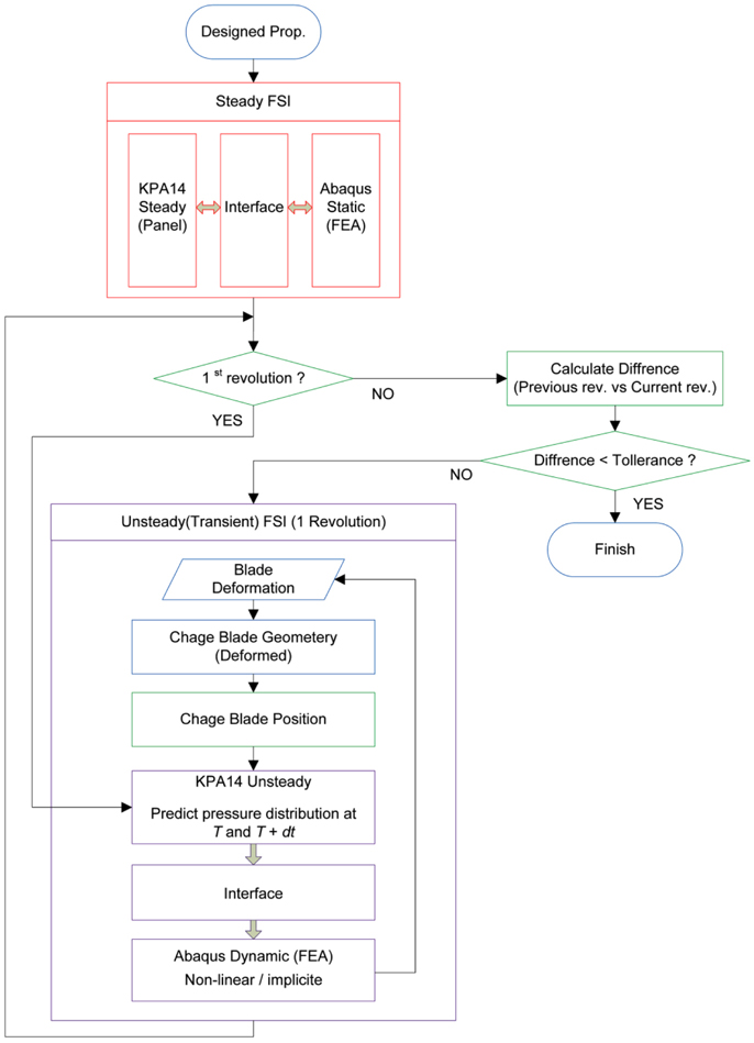
A basic interface structure of the two-way coupled FSI, shown in Fig. 4, consists of a BEM panel code (KPA14) for calculating the hydrodynamic force acting on the blade surface and a nonlinear FEM solver (Abaqus Standard) for calculating the structural deforming response, rotational body force (Coriolis force and centrifugal force), and added mass damping of the unsteady transient flow condition.
In steady-state FSI analysis, it is not necessary to consider the change in pressure distribution and the blade fluttering effect according to the blade position, so ★ items are excluded. The convergence is determined by the progress of comparison of geometrical differences from the former step (steady) and the former revolution (transient). Thus it is considered as converge when the maximum difference of nodal point is less than 0.01% of propeller diameter in the iterative FSI analysis.
>
Process for initial geometry prediction
The pattern of blade deformation depends on the properties of the materials used in manufacture and the ply stacking condition such as the main orientation, as well as the loads acting on the blade. This means that the process of predicting the initial blade geometry, which is dependent on the materials and ply stacking conditions, requires that the design geometry be determined at given propeller execution conditions.
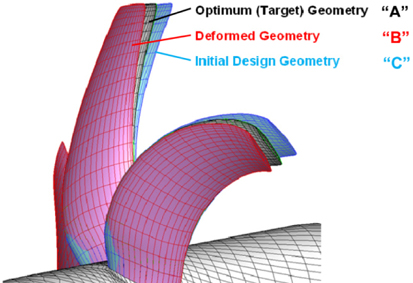
Assuming that the optimum geometry for the propeller design condition is the “A” blade and the flexible propeller is manufactured with this geometry and is in operation, its shape would be deformed to “B”. The “B” blade has completely different geometry than the optimal design in Fig. 5. Thus, the initial design process should be adapted to the geometry design of the marine propeller with the shape of the “C” blade, which is estimated by the reverse engineering method presented by Jang (2012). Then, the blade would be changed to the target geometry for the existing driving conditions. The reverse engineering algorithm for blade initial design shown below Fig. 6.
>
Unsteady transient FSI procedure
Time domain-based FSI analysis of the propeller’s blade position in the wake field is required to more accurately predict the performance and evaluate the structural strength. Rotating blades in the nonuniform inflow flow field have a “fluttering” vibration behavior caused by the change in pressure distribution and blade deformation from the response of the pressure load on the surface. Unlike the aviation propeller and wind turbine blade which act in low density air, the marine propeller cannot ignore the damping effect of the added mass on the blade surface and vibrates in the ship’s wake. Thus, in this study, we considered the hydrodynamic damping effect of the added mass by applying the acoustic medium around the propeller blades.
To perform unsteady transient analysis (dynamic analysis of Abaqus Standard), it is impossible to carry out the prediction of deformed shape at
Steady analysis for the initial convergence is performed prior to the unsteady analysis in order to reduce computing time since the transient analysis can start with the result. The convergence check of the total unsteady analysis is determined by comparing the geometrical difference between the present and the former revolution positions.
A comparison and review of experimental and computational results in the literature were conducted to verify the BEM-FEM-based steady and transient FSI analysis presented in this study. Since published references that contain both measured experimental data as well as the geometric/material properties of propellers is limited, the propellers validated in each analysis are different.
Chen et al. (2006) and Young (2008) present results for their experiments and FSI analysis of a six-bladed 610 mm diameter carbon fiber reinforced plastic propeller, manufactured at A.I.R. Fertigung-Technologie, GmbH in Hohen Luckow, Germany, and tested in the Naval Surface Warfare Center, Carderock Division (NSWCCD). In particular, Young (2008) conducted the validation of the proposed analytical method using the BEM-FEM FSI algorithm to compare the thrust, torque, and efficiency of a full-scaled open water model test for a “rigid” propeller P5471 and a “flexible” propeller P5479.
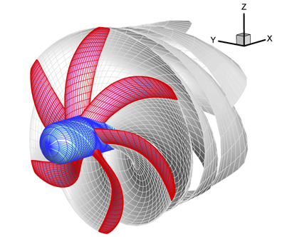
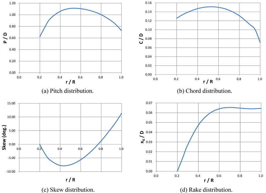
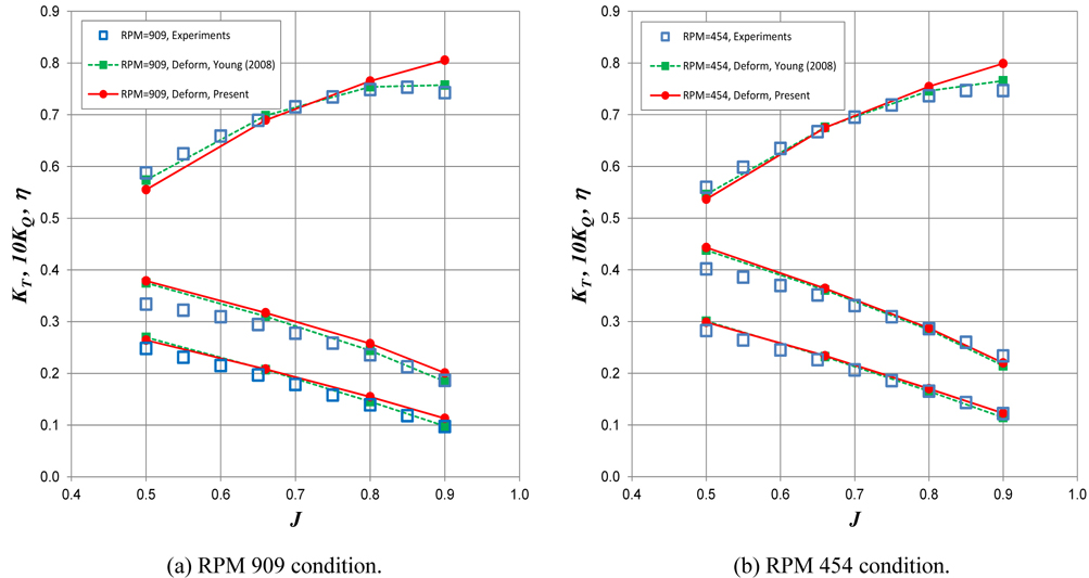
In this study, we validate this analytical method by comparing our results with Young’s (2008) experimental and analytical results for propeller P5479. The geometry of propeller P5479 is shown in Fig. 8. This is a useful exercise for our verification because this propeller has significant hydro-elastic behavior. Isotropic homogeneous material (not a real ply stack model) is applied in the analysis. The material properties extracted by Liu et al. (2007) are E1 = 138.9
The mesh size of the BEM analysis is 40 × 20 for each chord (from face to back side) and span direction. We apply a cosine spacing for chord direction and a half cosine spacing for span direction to dense toward tip to faithfully reflect the leading/ trailing edge and tip geometry of the blades. A total of 6400 elements (40 × 40 × 4 for chord, span, and thickness direction) are composed for the structural finite element analysis. We introduce an inverse distance weighting algorithm for the three-dimensional interpolation to share the different information at the calculating points.
FSI analyses are conducted under two operating conditions, RPM = 909 and 454, and they are compared to the NSWCCD test and to Young’s (2008) calculations at the advance ratio (
A marine propeller operates in the complex flow field condition known as the ship’s wake. The composite material marine propeller, in particular, must undergo hydro-elastic response analysis for unsteady conditions because its shape changes according to the blade position in the wake. Therefore, consideration of its structural safety, such as the risk of delamination due to fatigue and accurately predicting its performance, cannot be ignored.
The damping induced by the hydrodynamic added mass significantly affects the elastic response of the propeller blade in water. Thus hydro-elastic analysis that considers the so called “wet” condition effect should be conducted. In the research of Chen et al. (2006), Young (2007a; 2008), and Motley et al. (2009), this elastic vibration effect was estimated using the potential- based BEM and the results were applied directly to the structural mass and damping coefficients.
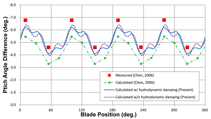
In this study, however, the added mass effect is considered by adapting the acoustic medium field and applying it as a pressure component on the blade surface directly. We compare the results from our proposed method with the measured and calculated results of Chen et al. (2006).
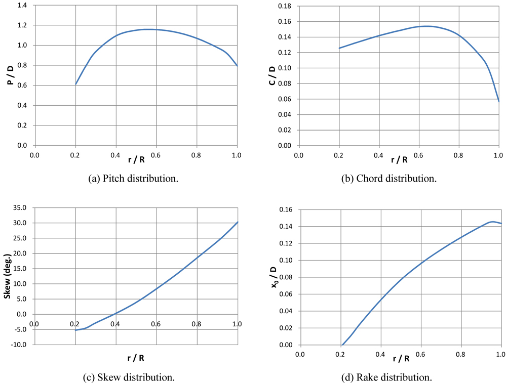
The propeller used in the analysis is a P5475 (Fig. 10), which deforms in actual conditions significantly enough to validate the analysis algorithm and the Laser Doppler Velocimetry (LDV) measured result of the pitch deformation published in Chen et al. (2006). Material properties of the P5475 are E1 = 139.0
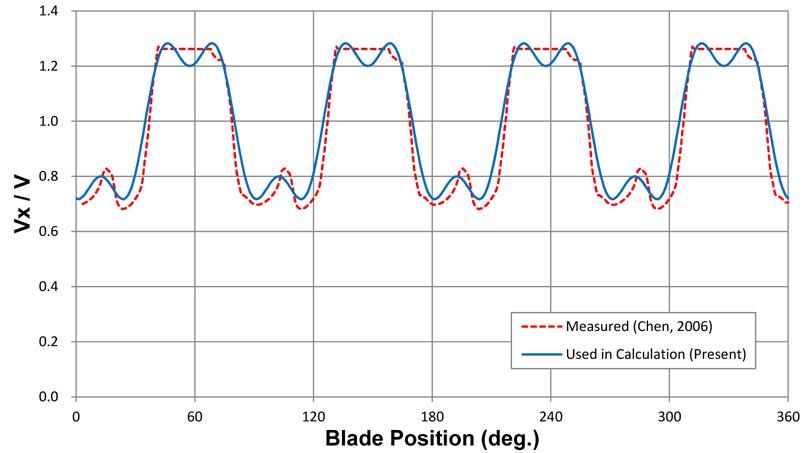
A wake screen was adapted to simulate the 4-cycle wake flow for measuring the hydro-elastic behavior in the unsteady flow field at NSWCCD, and the 4-cycle wake flow condition is applied to the FSI analysis. The mean velocity of inflow in the tunnel was 5.03
Pitch variations were measured by video cameras at two points, 10° and 55°. Propeller rotation was 750
The proposed unsteady transient algorithm is more accurate than the VLM-FEM FSI method regarding mean deformation. The difference between an analysis result that considers added mass due to the vibrating blade (“wet” condition) and a result that considers only material/structural damping (“dry” condition) is not significant. But considering that the purpose of the unsteady FSI analysis of a marine propeller in a wake field is for accurate performance prediction and structural safety evaluation, we believe that the proposed unsteady transient analysis under “wet” conditions can give more accurate and realistic prediction results for deformed geometry and variations.
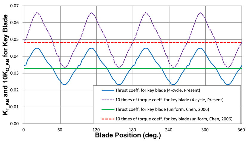
The calculated variations of the thrust and torque coefficients for the key blade in the four-cycle wake flow and the measured data from the composite propeller P5475 at
>
Natural frequency analysis for dynamic stability evaluation
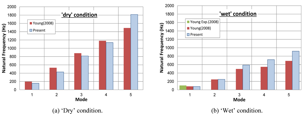
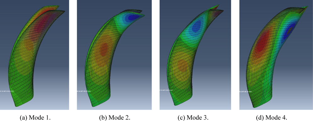
Natural frequency analyses of propeller P5479 rotating at 909RPM for “dry” and “wet” conditions are conducted and the analyzed natural frequencies of each mode are compared with the measured (“wet” condition, mode 1) and calculated results of Young (2008) in Fig. 14. And the blade shapes under “wet” conditions for each mode are shown in Fig. 15.
Since a flexible (or composite material) propeller is affected not only by the pressure changes acting on the blade but also the body forces from the rotational motion, such as the centrifugal force, the Coriolis force, and the “fluttering” hydro-elastic behavior in wake field; it is not easy to predict the propulsion performance, the initial geometry with respect to deformation, and the structural strength at the design stage.
The BEM-FEM-based practical hydro-elastic algorithm for a flexible marine propeller is developed for blade and ply orientation design to address performance prediction and structural evaluation. The study contents are as follows: 1) BEM code does not consider viscous effect and effective wake. However, it still gives sufficient accuracy and short computing time to apply propeller design stage. Therefore BEM-FEM FSI methodology is proposed for practical application to flexible marine propeller design instead of the more elaborate CFD-FEM FSI analysis.2) Panel code (KPA14) is used for hydrodynamic analysis to predict pressure loads on the propeller blade and a commercial FEA tool (Abaqus 6.12 Standard, Static and Dynamic option) is used for nonlinear analysis to calculate blade deformation and evaluate strength. An interface code is developed to connect these two analysis tools and perform FSI analysis.3) A three-dimensional continuum shell element is introduced for the FEA, which has merits in its easy modeling of composite material ply and its ability to reflect the structural behavior of objects having three-dimensional geometry.4) The hydrodynamic damping effect of added mass, which is induced by the elastic behavior of the propeller blade, are applied to the FEM for acoustic fluid mediums and as composing system equations of motion for pressure on the surface and the structural deformation of blade geometry, unlike existing studies.5) A validation study for the proposed steady and unsteady transient algorithm for composite propeller FSI analysis is conducted by comparing our study results with published experimental and analytical results on flexible propellers composed of orthotropic-homogeneous materials. As a result, the usefulness of the proposed practical methodology was confirmed.
Further study of the application of composite material ply structure in the FSI methodology will be conducted for further analysis of the composite material propeller. And future research will address the optimum stack algorithm that satisfies both structural strength and performance optimization for off-design operation conditions. In addition, CFD-FEM FSI methodology will be developed to improve hydro-elastic analysis accuracy.