Recently, because of rapid industrialization and informatization, considerable attention has been paid to environmental pollution and its effects on the human body. From this rapid change, the problem of electromagnetic interference or compatibility (EMI/EMC) caused by electronic devices and electric appliances has worsened because of the prevalent use of communication products such as mobile phones. The electromagnetic wave problem is not far away from our daily lives since it is closely related to modern life, in which TVs, PCs, and mobile phones are used. The human body directly exposed to these electromagnetic waves can face serious problems such as skin irritations; hallucinations; sleep disturbances; learning ability degradation; child growth distrurbances; various cancers such as lymphatic cancer, breast cancer, and brain tumors; myocardial infarction; infertility; birth defects; miscarriages; headaches; depression; and DNA damage. With respect to these problems, the World Health Organization (WHO) has published a considerable amount of literature. Further, many incidents of problems in the fields of operation and production have been reported because of the malfunctioning of or errors in devices throughout the industries, causing a serious safety problem for the operators. In the defense industry, it has also been reported that communication redevices such as defense radars have malfunctioned. To shield this EMI, various methods have been used. In general, metalbased materials are used as EMI shield materials. However, recently, because of the increasing trend of lightweight devices, and from the viewpoint of energy reduction, many studies have been conducted on the use of polymeric materials, which are lighter than metal-based materials. However, in general, polymeric materials have no effect as an EMI shield. Therefore, in order for polymeric materials to exhibit a shielding performance, many studies have been conducted on materials that can effectively shield from EMI. These studies produce a plastic-reinforced composite that not only has good conductivity, but also absorbs electromagnetic waves because of thecoating of a transition metal such as Cu and Ag. However, although using this transition metal can improve the electromagnetic shield performance, when such metal is used, there are problems of high price and oxidation of the metal. Hence, the use of this metal is not preferred [1-9].
Recently, in order to develop composite fillers containing dielectric materials, a method that uses a carbon-based filler, which is a conductive nanomaterial, was investigated. Kim and Kim [10] attempted to determine the characteristics of electromagnetic waves by utilizing the composite laminates of carbon nanotubes. Han
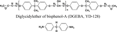
The fabric fiber used as reinforced material in this study was T300 fabric fiber CO6644B (weight, 300 g/m2) manufactured by TORAYCA®, and the epoxy resin used as the matrix was YD- 128 (e.e.w., 184-190 g/eq, viscosity: 11 500-13 500 cps) based on the diglycidylether of bisphenol-A (DGEBA), which is a bifunctional epoxy oligomer manufactured by Kukdo Chemical Co. Ltd. As a hardener, 4,4’-diaminodiphenylmethane (DDM), a product of TCI, was used, and methylethylketone (MEK) was used as a diluent to lower the high viscosity of YD-128. The chemical structure of the epoxy resin and the hardener used in this study is shown in Fig. 1 [12].
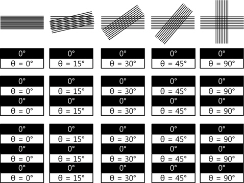
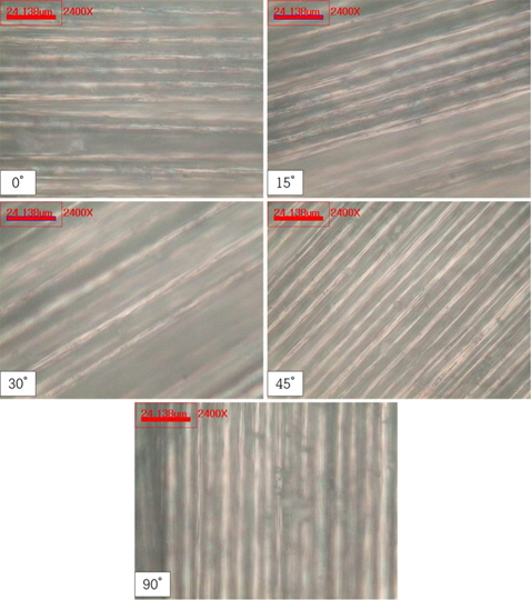
The epoxy resin and the hardener DDM were mixed in a 1:1 equivalence ratio and melted at 70℃, and MEK (weight ratio, 1:1) with epoxy resin was added to the dilute solution. The carbon fiber was impregnated with epoxy resin, and then a unidirectional carbon fabric prepreg was produced. Then, as shown in Fig. 2, based on an orientation angle of 0°, the orientation angle of the carbon fiber was changed to 0, 15, 30, 45, and 90°, and 2, 4, and 6 plies were stacked for each orientation angle. After this, the plies were hardened by vacuum bag molding for 180 min in order to produce carbon fiber redevices inforced plastic (CFRP). Fig. 3 shows the optical microscope image based on the orientation angle.
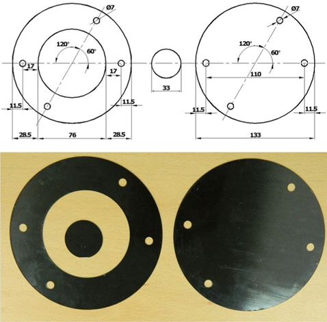
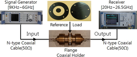
The CFRP produced, as shown in Fig. 2, was modified to be a specimen having the dimensions of ASTM D4935-10, as shown in Fig. 4a, which produced a specimen shown in Fig. 4b. Further, as shown in Fig. 5, the electromagnetic strength was measured directly through the specimen materials using a flange coaxial transmission line fixture. This was in order to measure the EMI shield efficiency. Asystem was also configured using an electromagnetic test receiver and a signal generator.
The concept of an EMI shield is to absorb or reflect the waves through desired materials such that the external waves shall not be transmitted into an indoor environment or system. The shield capability can be defined by the extent to which it can attenuate an electromagnetic wave introduced into an object.
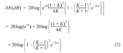
Considering the material thickness and electrical characteristics, we can derive the following equation:

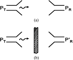
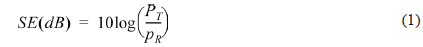
where denotes the ratio between electromagnetic impedance and shield material impedance; t, the material thickness; γ, the propagation constant (=α+iβ) of the electromagnetic wave; and α, the attenuation constant of the electromagnetic wave. In Eq. (2), the first term is called adsorption loss, the second term is called reflection loss, and the third term is called multi-reflection correction. The EMI shield effectiveness is found by the sum of the absorption, the reflection of the electromagnetic wave introduced, and the multireflection between the medium boundaries. The electromagnetic wave can be shielded effectively by utilizing these losses according to the characteristics of the electromagnetic wave to be shielded. That is, when electromagnetic energy arrives at an arbitrary object (shielding material), the travel path of the electromagnetic wave is distributed by three phenomena, namely reflection, transmission, and adsorption. Here, shielding is defined by combining the reflection and the adsorption when a criterion is set within a system. With respect to the actual electromagnetic measurement, the signal that is generated at the antenna on the generation side is called PT, and the signal received by the antenna on the receiving side is called PR. Assuming that a signal on the receiving side, in which a shield is arranged between the generation and the receiving sides using a shielding material, is P’R, we can calculate the effectiveness of the EMI shield by using Eq. (1). Fig. 6 shows this arrangement [12].
In order to measure the electrical conductivity, the electrical characteristics (resistance, R) were measured by a four-terminal method using a KEI-THLEY 580 Micro-Ohmmeter when the orientation angle was 0/0, 0/15, 0/30, 0/45, and 0/90. Then, according to Eq. (3), the volume resistivity (
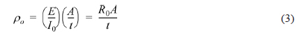
where E is the voltage (V) applied to the specimen;
3. Experiment Results and Discussion
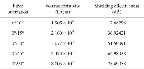
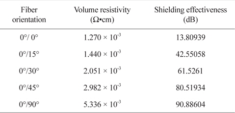
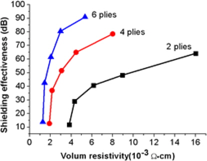
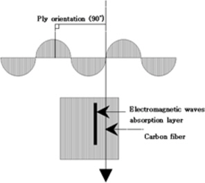
The CFRP has a low resistance rate of 10-2~10-3 Ω•cm because of the conductivity of the carbon fiber. These electrical characteristics were measured with respect to the volume resistivity of the specimens of 2 plies, 4 plies, and 6 plies by changing the orientation angle, as shown in Fig. 2. Tables 1-3 and Fig. 7 show the characteristics. Theoretically, a specimen that has an orientation angle of 0° and a low electrical resistance value should have the best reflection effect of an electromagnetic wave. However, since the material used in this test was fiber-reinforced plastic that has thermal and electrical anisotropy, the shielding effectiveness measured as the orientation angle showed that the angle of 90°, which was perpendicular to the electromagnetic wave propagation, had the maximum effectiveness, as shown in Fig. 7. This result was obtained because of the effect of the fiber arrangement in the horizontal direction of the electric field, while considering the conductivity loss. That is, when an electric field and resistance conductor are placed in parallel, a current is generated, which can explain the absorption of electromagnetic waves as a resistance thermal loss [12].
[Table 1.] Volume resistivity as to carbon fiber orientation angle in 2 plies

Volume resistivity as to carbon fiber orientation angle in 2 plies
[Table 2.] Volume resistivity as to carbon fiber orientation in 4 plies

Volume resistivity as to carbon fiber orientation in 4 plies
[Table 3.] Volume resistivity as to carbon fiber orientation in 6 plies

Volume resistivity as to carbon fiber orientation in 6 plies
The experiment of the EMI shield was performed to find out the electromagnetic shielding performance according to the number of plies and the orientation angle of the CFRP. The frequency ranged between 500 MHz and 3 GHz, and the reference was set as 20 dBmV. Figs. 9-13 show the results of the electromagnetic shielding performance based on the changes in the number of plies of the carbon fiber while the orientation angle θ was constant.
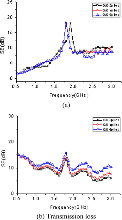
Fig. 9 shows the shielding effectiveness when the orientation angle θ was 0°. Fig. 9a shows the electromagnetic reflection loss. With respect to the reflection loss based on the number of plies, assuming 100% in the case of 2 plies on average, there was slight decrease of 6.2% in the case of 4 plies and 7.7% in the case of 6 plies. Fig. 9b shows the absorption loss of the electromagnetic wave. As shown in the figure, as the number of plies increased, the shielding performance increased, while the performance difference showed a slight increase of 7.8% in the case of 4 plies and 17.4% in the case of 6 plies, assuming 100% in the case of 2 plies. According to the results shown in Fig. 9, at an orientation angle θ of 0°, the reflection loss as to the number of plies had a maximum difference of 6.0 dB at a peak value according to the number of plies, while the adsorption loss was influenced minimally (3 dB on average).
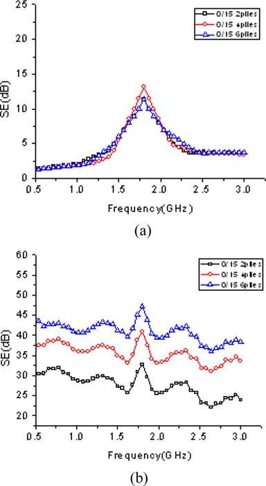
Fig. 10 shows the shielding effectiveness when the orientation angle θ was 15°. Fig. 10a shows the electromagnetic reflection loss. As shown in the figure, the reflection loss according to the number of plies decreased by 0.8% in the case of 4 plies and slightly increased by 1.2% in the case of 6 plies, assuming 100% in the case of 2 plies. Fig. 10b shows the electromagnetic absorption loss. The shielding performance increased with an increase in the number of plies. The performance difference increased by 27.5% in the case of 4 plies and 46.9% in the case of 6 plies, assuming 100% in the case of 2 piles. According to the results shown in Fig. 10, when the orientation angle θ was 15°, the effect on the reflection loss was maximum, i.e., 1.5 dB, at the peak value showing a slight difference. The effect on the adsorption loss, which is 13 dB on average, increased according to the number of plies.
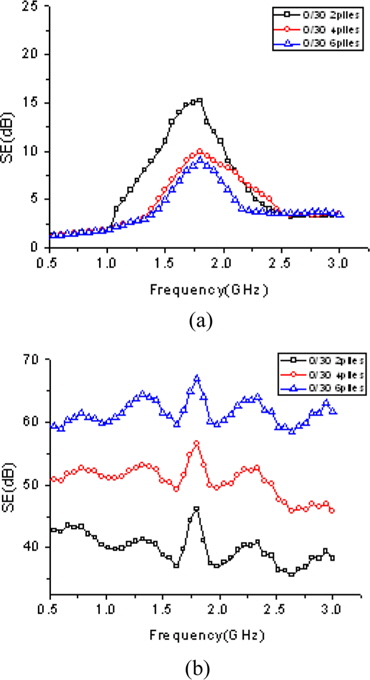
Fig. 11 shows the shielding effectiveness when the orientation angle θ was 30°. Fig. 11a shows the electromagnetic reflection loss. As shown in the figure, the reflection loss according to the number of plies decreased by 24.9% in the case of 4 plies and 34.7% in the case of 6 plies, assuming 100% in the case of 2 plies. Fig. 11b shows the electromagnetic absorption loss. The shielding performance increased with an increase in the number of plies. The performance difference increased by 26.3% in the case of 4 plies and 50.9% in the case of 6 plies, assuming 100% in the case of 2 piles. According to the results shown in Fig. 11, when the orientation angle θ was 30°, the effect on the reflection loss showed a maximum difference of 6.2 dB at the peak value. The effect on the adsorption loss, which is 21 dB on average, increased according to the number of plies.
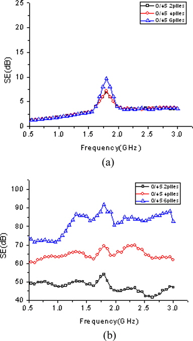
Fig. 12 shows the shielding effectiveness when the orientation angle θ was 45°. Fig. 12a shows the electromagnetic reflection loss. As shown in the figure, the reflection loss according to the number of plies decreased by 0.8% in the case of 4 plies and 5.7% in the case of 6 plies, assuming 100% in the case of 2 plies. Fig. 12b shows the electromagnetic absorption loss. The shielding performance increased with an acincrease in the number of plies. The performance difference increased by 34.8% in the case of 4 plies and 67.0% in the case of 6 plies, assuming 100% in the case of 2 piles. According to the results shown in Fig. 12, when the orientation angle θ was 45°, the effect on the reflection loss showed a maximum difference of 2.6 dB at the peak value. The effect on the adsorption loss, which is 32.3 dB on average, increased according to the number of plies.
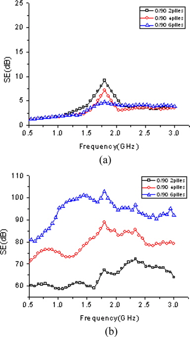
Fig. 13 shows the shielding effectiveness when the orientation angle θ was 90°. Fig. 13a shows the electromagnetic reflection loss. As shown in the figure, the reflection loss according to the number of plies decreased by 16.4% in the case of 4 plies and 12.1% in the case of 6 plies, assuming 100% in the case of 2 plies. Fig. 13b shows the electromagnetic absorption loss. The shielding performance increased with an increase in the number of plies. The performance difference increased by 22.3% in the case of 4 plies and 41.6% in the case of 6 plies, assuming 100% in the case of 2 piles. According to the results shown in Fig. 13, when the orientation angle θ was 90°, the effect on the reflection loss showed a maximum difference of 4.3 dB at the peak value. The effect on the adsorption loss, which is 32.3 dB on average, increased according to the number of plies.
Summarizing the results of Figs. 9-13, we found that as the orientation angle θ increased, the variance of the EMI shield performance also increased according to the number of plies. With respect to the reflection loss, a certain difference was observed according to the number of plies, but overall, the effect was minimal. With respect to the adsorption loss, the orientation angle increased as observed. This was due to a mixture of the increasing effect of the electromagnetic adsorption according to the orientation angle and the increasing areas of electromagnetic adsorption according to the number of plies. Further, at the angles of 0° and 15°, as the frequency increased, the adsorption loss tended to decrease, while all the frequency bandwidths showed a similar result at the angles of 30° and 45°. In the case of 90°, as the frequency increased, the absorption loss tended to increase. This phenomenon can be explained as follows: when the orientation angle increased, it became close to the electromagnetic propagation direction, which was 90°, thereby increasing the amount of adsorption loss.
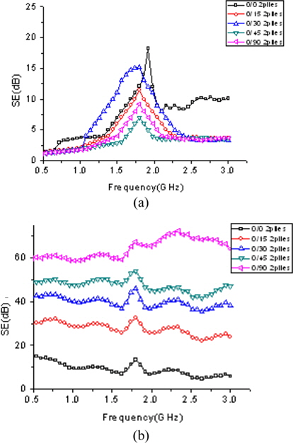
Fig. 14 shows the EMI shield performance result when the number of plies was 2. Fig. 14a shows the electromagnetic reflection loss. The effect on the reflection loss according to the orientation angle decreased by 39.5% at 0/15, 17.8% at 0/30, 56.5% at 0/45, and 50.3% at 0/90, assuming 100% at 0/0. Fig. 14b shows the adsorption loss of the electromagnetic wave acincrease cording to the orientation angle, showing an increasing trend of 146.1% at 0/15, 246.5% at 0/30, 309.7% at 0/45, and 445.5% at 0/90, assuming 100% at 0/0. The results shown in Fig. 14 revealed that the effect on the reflection loss in the case of 2 plies according to the orientation angle was a maximum of 2.9 dB at the peak value, and the effect on the adsorption loss increased by 52.4 dB on average.
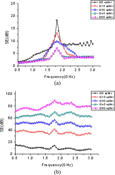
Fig. 15 shows the EMI shield performance result when the number of plies was 4. Fig. 15a shows the electromagnetic reflection loss. The effect on the reflection loss according to the orientation angle decreased by 37.01% at 0/15, 35.3% at 0/30, 54.1% at 0/45, and 56.4% at 0/90, assuming 100% at 0/0. Fig. 15b shows the adsorption loss of the electromagnetic wave according to the orientation angle, showing an increasing trend of 191.1% at 0/15, 306.0% at 0/30, 412.4% at 0/45, and 518.9% at 0/90, assuming 100% at 0/0. The results shown in Fig. 15 revealed that the effect on the reflection loss in the case of 4 plies according to the orientation angle was a maximum of 11.0 dB at the peak value. The effect on the adsorption loss also increased by 65.8 dB on average.
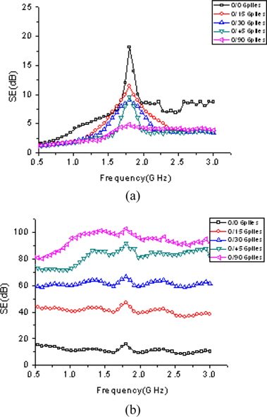
Fig. 16 shows the EMI shield performance result when the number of plies was 6. Fig. 16a shows the electromagnetic reflection loss. The effect on the reflection loss according to the orientation angle decreased by 33.5% at 0/15, 41.8% at 0/30, 50.2% at 0/45, and 52.7% at 0/90, assuming 100% at 0/0. Fig. 16b shows the adsorption loss of the electromagnetic wave according to the orientation angle, showing an increasing trend of 208.3% at 0/15, 345.8% at 0/30, 483.3% at 0/45, and 558.5% at 0/90, assuming 100% at 0/0. The results shown in Fig. 16 revealed the effect on the reflection loss in the case of 6 plies according to the orientation angle, which was a maximum of 2.9 dB at the peak value. The effect on the adsorption loss also increased by 77 dB on average.
Summarizing the results of Figs. 14-16, we found that when the number of plies was constant, the EMI shield performance increased with an increase in the orientation angle of the carbon fiber. The reflection loss showed a certain difference according to the orientation angle, although the overall effect was minimal. Further, as the orientation angle increased, the reflection loss tended to decrease. This phenomenon can be explained as follows: As the orientation angle increased, it became close to 90°, which was perpendicular to the electromagnetic propagation direction. This thereby increased the adsorption loss of the electromagnetic wave while decreasing the reflection loss. Furthermore, most of the specimens showed an increasing trend of the EMI shield performance around 1.8 GHz. This was due to the characteristics of the carbon fiber with respect to the electromagnetic wave. Finally, the adsorption loss showed an increasing trend when the changes in the orientation angle became relatively large.
The changes increased in the order of 2 plies, 4 plies, and 6 plies, which showed the largest increase. This indicates that as the number of plies increased, the adsorption region of the electromagnetic waves also increased.
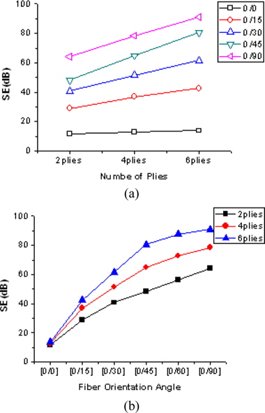
Fig. 17 shows the average variations of the EMI shielding effectiveness measured for each specimen. As shown in the figure, the EMI shield performance increased when the orientation angle and the number of plies increased. Further, as the orientation angle increased, the gradient of the graph also increased. That is, when the orientation angle was close to 90°, which was the electromagnetic wave propagation angle, the shielding amount also increased. This result implied that the EMI shield performance of CFRP was influenced more by the orientation angle than the number of plies.
In this study, we studied the EMI shield performance according to the orientation of the lamination of CRFP and the number of plies. We derived the following results:
It was verified that as the number of plies of the CFRP increased, the EMI shield performance increased. This was due to the effect of the large absorption area for the electromagnetic waves.
It was verified that as the orientation angle of the CFRP increased, the EMI shield performance increased. This indicates that as the orientation angle increased, the angle became close to 90°, which was perpendicular to the electromagnetic wave propagation direction. Therefore, the absorption loss of the electromagnetic wave increased.
It was verified that as the number of plies and the orientation angle increased, the reflection loss tended to decrease slightly while the absorption loss increased. This was due to the large absorption region of the electromagnetic wave (the orientation angle and the number of plies).
Irrespective of the lamination direction and the number of plies, most specimens showed an increasing performance of the EMI shield at a frequency of around 1.8 GHz. This can be explained by the characteristics of the electromagnetic wave of the carbon fiber.
The orientation angle influenced the effectiveness of the EMI shielding more than the number of CFRP plies. These results suggested that when designing electromagnetic shield materials and components using the carbon fiber, the frequency bandwidth required for the EMI shield and the shield performance must be satisfied by adjusting the orientation angle and the number of plies geometrically.