The development of industrial motion control systems has expanded considerably even though it just emerged over the last several decades. The most significant component of a motion control system is the motion controller, with the control strategy being the main technique. Generally, industrial motion control schemes must solve two major problems. The first problem deals with the tracking command. In most of industrial motion controllers, the motion trajectory, which is pre-defined by the input parameters, is generated as a tracking command. Hence, the motion controller assesses the performance of how well the actual motion follows what was determined in advance. Traditional solutions utilize the proportional integral derivative (PID) algorithm, which is applied in various manufacturing systems. Qu and Wang [1] implemented a PID controller in the programmable multi-access controller (PMAC) card to control the AC servo motor. However, this design, which is based on a complex debugging process, depends on the specific control device. In [2], the authors introduced a least square parameter estimation algorithm for PID control, which made movement smoother. However, the parameter estimator algorithm increases the computational cost and decreases the speed of serial communication, which does not satisfy the high performance requirements in industry. Zhao and Zhang [3] presented a fractional-order PID scheme that continuously alters the frequency response of the system. This method is not trivial to implement in practical uses and does not guarantee satisfactory communication speed. The second problem tackles the disturbance rejection characteristics of the system. On the motor shaft, torque disturbance is common in the manufacturing environment. Thus, there is a need to design a controller for compensating for these problems. Tran et al. [4] studied motion control on the electronic-centralized aircraft monitor (ECAM) system, introducing the auto-tuning PID velocity controller to overcome the uncertainties. The gains realized from this controller are updated constantly to guarantee the consistency of system performance under varying working conditions. However, this controller depends on only one specific motion system and cannot be widely implemented. Several additional control methods have been introduced, such as optimal control [5], adaptive robust control [6], adaptive robust neural network [7] [8], variable structure control [9] and linear-quadratic regulator (LQR) [10]. However, these solutions do not incorporate existing human knowledge into their algorithm. Owing to the system complexity, nonlinearity and uncertainty, it is difficult to obtain good performance in a variety of manufacturing machines based on the exact mathematical models.
An intelligent control technique, especially the fuzzy control technique (FCT), can overcome the difficulties created by conventional methodologies. This is a knowledge-based controller that is focused on the reasoning mechanism rather than concentrating uniquely on the model of the system. In [11], researchers investigated a control diagram for high speed control of an interior permanent magnet synchronous motor by computing the operational point. Then in the fuzzy logic controller, these values are input and the parameters of the controller are tuned by a genetic algorithm. Conversely, this method only presents analysis and development theory. However, it lacks practical implementation in manufacturing conditions. Other researchers [12] designed a two-input normalized linear fuzzy logic controller incorporated with a traditional derivative controller to control both the linear and nonlinear systems. However, this controller is still not suitable for most manufacturing machines because of the high computational burden and complex use. Authors in [13] researched a switching mechanism between traditional PID-based and fuzzy-PID-based controllers using a generic technique for optimizing the scaling values. However, the results have only obtained in a laboratory environment where practical programming and a debugging control language are absent.
In modern and practical production environments, a feedforward scheme promises to improve the tracking performance. Tsai et al. [14] indicated a complete feed-forward compensator in a computer numerical control (CNC) machine. The structure of the feed-forward control can also be applied in the motion planning algorithm, where it maintains the characteristics such as optimizing time, reliability and precision. For the other implementation issues, authors [15, 16] suggested a high order feed-forward planning strategy resulting in a significant performance improvement. The details of the fourth-order trajectory planning algorithm proved a practical, reliable and accurate outcome. In [17, 18], the stabilizing design method of a motion controller in the presence of uncertainty and disturbances is discussed by using the robust internal loop compensator. This design provides a systematic approach to the problem of robust stability and the desired performance in the presence of uncertainties.
In this paper, we presented a feasible and effective design of a fuzzy self-tuning PID with a feed-forward controller, which offers great precision and high performance applicable in the machining industry. This knowledge-based control scheme is robust enough to handle systems with external disturbances to the motor shaft, model free systems, and systems for which accurate information is not required. The remainder of this paper is structured as follows. In Section 2, the proposed controller design is presented. Section 3 describes the whole motion control system. Experimental results are shown in Section 4. Finally, conclusions are discussed in Section 5.
2.1 Conventional PID Controller
Although the PID controller was well-known in various industrial areas due to its simple implementation and easy control, it revealed several drawbacks in modern industry. Basically, there were two methods to achieve the required performance gains-trial-and-error or analysis. It can be seen that the trial-and-error approach relies noticeably on the technician’s personal experience with a specific servo system. Once the significant practice becomes low or intuitive performance is unclear, it is difficult to know whether you have reached the optimal performance gains. Through analysis of the servo system, Ziegler and Nichols [19] introduced a method to tune three parameters of the PID controller. However, all three performance gains are inter-related, since altering one affects any of the previous adjustments. Moreover, the conventional PID controller does not yield reasonable performance over a wide range of operating conditions due to the fixed gain. Therefore, there is a critical need to design a high performance controller for modern industrial motion control systems.
2.2 Fuzzy Self Tuning PID and Feed-Forward Controller
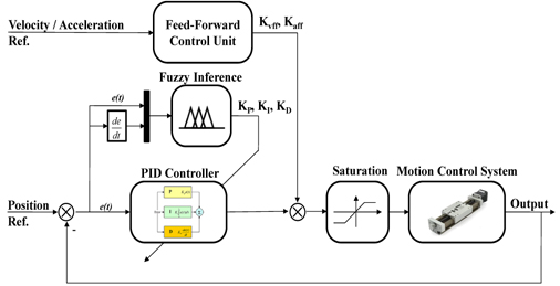
The coefficients of the conventional PID controller are not often adapted for nonlinear models with unpredictable parameter variations. To overcome these uncertainties, the PID controller was engineered to automatically tune the parameters, called fuzzy self-tuning PID (FPID), while maintaining the simple control characteristic and eliminating the steady state error. Nevertheless, with only a feedback control structure, the tracking errors due to servo lag phenomena still occur. One existing solution is to add the feed-forward control scheme into the main controller to enhance tracking performance. For this kind of design, the feed-forward control scheme is available to change the values of parameters in the position loop controller. In consequence, the overall controller is presented in Figure 1, which is composed of the feed-forward control unit, a fuzzy inference mechanism, and a self-adjusting PID controller. As can be seen from Figure 1, each of three gains K

where , : the control efforts of the feed-forward control unit and the fuzzy self-tuning PID controller respectively. : the error and deviation of error.
Position, velocity and acceleration references are inputs from the motion profile generator.
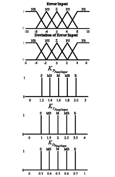
The first step in designing the fuzzy inference process is to establish the linguistic fuzzy variables for the inputs and outputs. In Figure 2, the inputs of fuzzy inference are error and deviation of error, while the outputs are used for adjusting the PID controller. The membership functions of these fuzzy sets are triangles and trapezoids because of simple and effective programming. In this research, the linguistic variables are assigned as negative big (NB), negative small (NS), zero (Z), positive small (PS) and positive big (PB) for both input sets. As a result,
The rule base includes a set of linguistic IF-THEN rules containing two antecedents and one consequence, as expressed in the following form:

where 1 ≤ x, y, z ≤ 5.
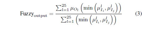
The conjunction of the rule’s antecedents is determined by the fuzzy operation intersection which is implemented by the minimum operator. The total number of IF-THEN rules is equal to the product of the number of fuzzy sets that make up each of the two fuzzy input variables. For that reason, a total of 25 fuzzy rules are required to represent each possible combination of the two fuzzy input variables used to create the output membership fuzzy sets. The fuzzy rules ensure that the output of the fuzzy controller improves the overall tracking performance.
The fuzzy inference engine uses the appropriately designed knowledge base to evaluate the fuzzy rules and produce an output for each rule. Table 1 shows the possible combinations of fuzzy values that are experienced by the drive system and the corresponding output membership function. Then the multiple outputs are transformed to a crisp output by defuzzification.

[Table 1.] Fuzzy rules of fuzzy tuner
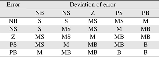
Fuzzy rules of fuzzy tuner
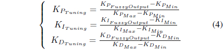
Then, the three outputs are substituted into the following equations to compute the tuning gains in (1).
A saturation unit is also incorporated in the overall controller structure. As such, the final output of the proposed controller is,

where , : the permitted maximum and minimum inputs to the servo drive system. : the output of saturation unit.
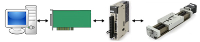
In Figure 3, a digital signal processing (DSP)-based motion control system is shown. The host is personal computer with the Windows 7 operating system. The proposed controller can communicate with the host through a peripheral component interconnect (PCI) bus. The motion controller outputs analog signals to the servo driver in order to provide control. In this research, the servo driver and servo motor are manufactured by YASKAWA. The servo motor, SGMJV-02ADA21 200W, has a 20-bit incremental encoder driven by a high performance servo driver, SGDV-1R6A01B.
In this system, the proposed DSP-based motion controller is designed with the CPU as a key component. This microprocessor handles multi-tasking operations such as, motion planning, motion detection, and arithmetic computation, based on the powerful resources available on-chip.
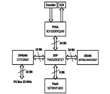
In Figure 4, the hardware design of the proposed controller consists of DSP, DPRAM, static RAM (SRAM), Flash, FPGA and other peripheral components. the user controls the full S-curve movement mode (acceleration mode) on the host computer. This controller communicates with the host through the PCI-bus at 33MHz, thus, it receives the motion command from the host. The high speed and reliable data communication is guaranteed by DPRAM which allows two directional operations simultaneously. The DSP reads the motion parameters in the shared memory area and calculates the smooth profile. Several motion coefficients are saved in SRAM in order to obtain them easily when needed by the CPU, and the data in Flash is used for the initial motion information and some boot functions. The DSP generates the profile based on polynomial equations. The command position is sent to the main controller as a reference signal. Then, the result of the computation is transferred to a digital-analog conversion. The servo driver receives analog control value and sends the feedback value to the motion controller. In this design, FPGA acts as the address decoder and receives the encoder signal.
The components of the software design include a graphical user interface (GUI), C++ and C programs. In the Windows OS, GUI allows a user to interact with the motion control system using imaging demonstrations rather than textual commands. Intuitively, parameters are input and displayed while the motion is executed. A motion library, programmed in Visual Studio 2008, helps to classify and synchronize the data flow between the host and the motion controller. At a lower level, the C program, mainly operating in Code Composer Studio version 3.3, manages most of the tasks of the motion controller.
To organize the program systematically and steadily, varieties of channels and commands are put forward. When motion is accomplished, the channel is ready. Otherwise, the channel is busy. The request status of the command first arrives to set the parameters in the C code program. The command executes when the preparation for motion is finished. During the process of motion, the command returns an error type if any error occurs. If not, the status of the command is ready for the next operation.
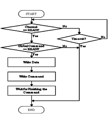
As shown in Figure 5, the global command that handles the communication of the host and the controller is presented. After the confirmation of the channel and global command being ready, data is written into the memory area correspondingly. The host sends the motion command which takes into account the acceleration mode, blending mode and step mode to start the motion.
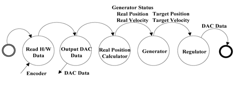
The main interrupt service routine (ISR) is described in Figure 6. Initially, hardware data is read from the encoder to update the feedback signal. In this stage, positive/negative limit sensors and home sensors are also renewed. Later, the digital-to-analog converter (DAC) data of the previous computation is output. From the encoder values, actual positions can be obtained. Consequently, a motion profile is generated referencing its real position and velocity in the generator function. Afterward, the difference between the command or target values and the actual values is calculated and transmitted into the fuzzy self-tuning PID controller. The final DAC data is recorded in the register before the ISR ends.
In the C program, there is a main loop which continuously monitors the execution of the motion controller. The loop detects the signal from the sensors, the error in the amplifier and the encoder or a large gap between the command value and the actual value. It also verifies whether motion is in-position or not.
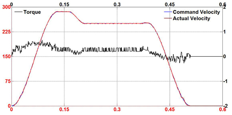
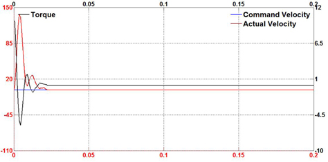
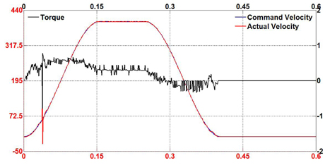
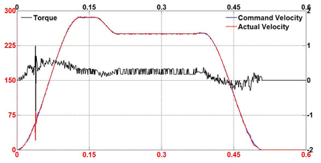
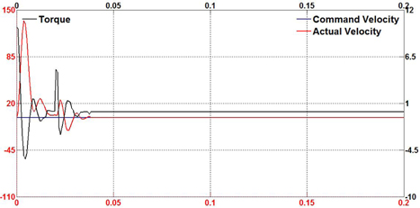
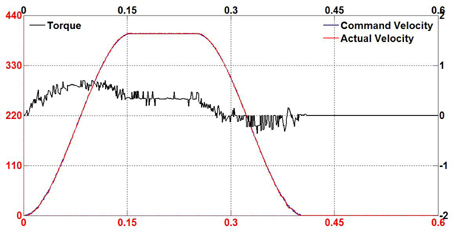
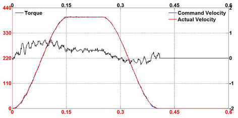
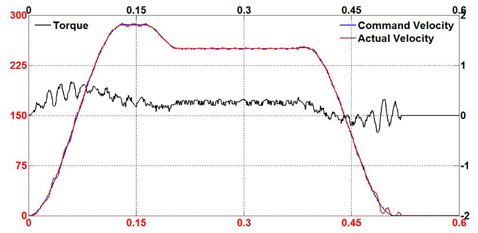
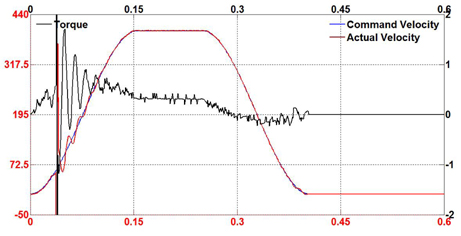
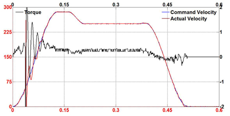
In order to evaluate the performance of the proposed fuzzy selftuning PID and feed-forward controller, several experiments were conducted in a variety of machining conditions. The tests were also conducted using the conventional PID controller under the same conditions. The overall hardware of the motion system was operated and observed in three common modes: acceleration motion, blending motion and step motion. Also, three monitoring parameters were collected to clarify the status of the motion system. Command velocity plays a role as a reference signal from the motion profile generator while the actual velocity makes an effort to track the pre-determined path. The torque value is the output control torque of the proposed controller. Figure 7-9 show the tracking results of the proposed control scheme in all three modes. It can be seen that the fuzzy self-tuning PID and feed-forward controller brings the actual speed to the specified desired speed smoothly.
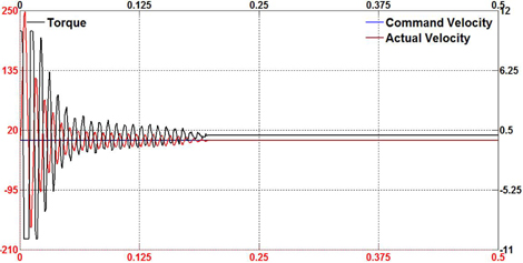
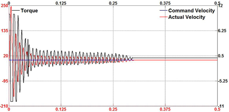
In comparison with the proposed controller, Figure 10-12 show the results of the experiments using the conventional PID controller. In both cases, it is also observed that the tracking responses swing when motion is in progress.
To demonstrate the capability and effectiveness of the proposed controller, external disturbance was randomly applied to the torque control on the motor shaft in the servo drive system while the experiment was on track. Figure 13-15 show the performance of the proposed controller design for both motion modes in the existence of external and sudden disturbance. It is noticed that the proposed controller effectively eliminates the disturbance and continues to track the desired velocity under these conditions. When the disturbance occurs, the motion system tends to oscillate or overshoot. Instantly, the control scheme adjusts to drive the servo motor to the desired profile.
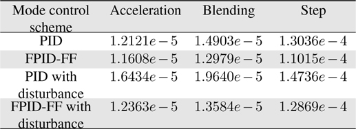
Figure 16-18 show the test results for the conventional PID controller under external disturbances for comparison with the proposed fuzzy self-tuning PID and feed-forward controller. It can also be seen that the conventional controller suffers from the disturbance with significant overshoot and undesirable oscillatory response. Table 2 shows the root mean square (RMS) error values during practical tests. From these results, it is suggested that the proposed motion controller generates high performance for industrial motion applications.
[Table 2.] Comparison of rootmean square tracking errors in test cases

Comparison of rootmean square tracking errors in test cases
A feasible and effective fuzzy self-tuning PID and feed-forward motion controller has been introduced in this paper. The resulting experiments have shown great tracking performance of the proposed controller, a smooth profile and real-time response. The practical implementation was accomplished on a DSP-based motion controller and a Windows-based software environment. Under these conditions, motion control engineers have the advantages of programming control and debugging methods to express the interest in accuracy manufacturing system. Therefore, the proposed controller applies to a wide range of industrial motion control systems.
In our future work, other algorithms such as linear/circular interpolation and a homing method will be implemented into the proposed controller. Additionally, although the current performance satisfies most of the requirements, motion synchronization should be considered in a multiple axes system.