검색 전체 메뉴
PDF
맨 위로
OA 학술지
Optimal Signal Amplitude of Orthogonal Frequency-Division Multiplexing Systems in Dimmable Visible Light Communications
  • 비영리 CC BY-NC
  • 비영리 CC BY-NC
ABSTRACT
Optimal Signal Amplitude of Orthogonal Frequency-Division Multiplexing Systems in Dimmable Visible Light Communications
KEYWORD
Visible light communication , OFDM , Dimming , Clipping
  • I. INTRODUCTION

    The demand for wireless data has increased considerably in recent years. As a new wireless medium, visible light communication (VLC) is a new candidate to convey data using light-emitting diodes (LEDs) [1-3]. The first standardization was completed by the 802.15.7 VLC Task Group [4]. VLC modulates data by blinking LEDs, which have rapid electrical responses. An electrical signal is converted to an opticalintensity signal via LEDs, which is known as intensity modulation (IM), and a noncoherent receiver, such as a photodetector (PD), restores the electrical signal proportionally to the received optical intensity, which is known as direct detection (DD). Considerable research has been conducted on VLC systems, such as implementation techniques [5-8], channel characteristics [9], multiple-input/multiple-output techniques [10, 11], orthogonal frequency-division multiplexing (OFDM) [12-19], and schemes for dimming requirements [19-43]. Dimming is a unique characteristic of VLC, which makes it different from conventional optical wireless communications (OWCs). The original lighting purpose of LEDs gives rise to the inherent constraint that the mean intensity matches the dimming requirements of the user. For ON-OFF keying (OOK) modulation, the ratio of the “ON” time to “OFF” time of the signal is adjusted in a transmission data frame to meet the dimming requirements, resulting in the design of a scheme maintaining the Hamming weights associated with the dimming requirement. Pulse-width modulation (PWM) is applied for dimming support [19-21], and can also be superposed with OOK and pulse-position modulation (PPM) [22, 23]. These schemes are simple, but they either produce marginal rate enhancement or are vulnerable to noise. Pulse-amplitude modulation (PAM) is used for VLC applications [24]. Analog dimming [25] adjusts the dc bias of the signal, such that the overall symbol levels meet the dimming targets. This is also simple, while incurring the cost of sophisticated intensity control and weakness to noise. Variable pulse-position modulation (VPPM) [26, 27] combines 2-PPM and PWM, which are responsible for communication and dimming, respectively. Pulse dual-slope modulation [28], which is a variant of VPPM, offers improved flicker mitigation. Multicoded VPPM [29] adopts cyclic M-ary PPM for higher rates. Time-multiplexed OOK [26,30] was developed to insert an ON or OFF time period without adaptive control of the mean optical power. Inverse source coding (ISC) was reported to outperform the time-multiplexed OOK and achieve the theoretical data rate bound asymptotically in a noise-free environment [31, 32]. Multiple PPM was proposed to have as much rate support as ISC [30,33,34]. Color-shift keying (CSK) [26, 35, 36] positions the signal constellation according to color and controls dimming by the signal amplitude (optical power) for multicolored VLC. Although CSK modulates the signal under the constraint of a fixed overall intensity, color-intensity modulation [37] allows the simultaneous use of colors and intensities for dimming support and outperforms CSK. In addition, multiple codeword allocation [38] was used for dimming support, and the channel coding issues for binary transmission in dimmable VLC using Reed-Muller codes [39,40] and turbo codes [41] were addressed. Moreover, a channel coding scheme for M-ary PAM was proposed [42]. Energy savings were also considered while satisfying the dimming requirements [43].

    This paper reports OFDM systems in dimmable visible light communications. Section 2 reviews the basic characteristics for OFDM systems and dimming in VLC. Section 3 reports the simulation environments, and the best bit-error rate (BER) and the corresponding optimal amplification depending on channel quality and dimming are obtained. Section 4 reports the conclusions.

    II. OFDM IN VLC

       2.1. Optical OFDM

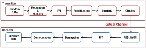
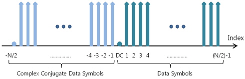
    OFDM is called multiple-subcarrier modulation (MSM) [44] in OWC. Because the intensity of an OFDM signal can be negative, two different techniques for generating nonnegative symbols suitable for IM have been proposed: DC-biased optical OFDM (DCO-OFDM) [3] and asymmetrically- clipped optical OFDM (ACO-OFDM) [45]. This paper uses the more commonly assumed DCO-OFDM, where a DC bias is applied to yield a nonnegative signal. MSM, which is realized by OFDM, offers a simple way of mitigating the fading effects resulting from delay spread [44], whereas it has poorer power efficiency than single-carrier approaches. Logically, optical OFDM in Fig. 1 is similar to radio-frequency (RF) OFDM, except for dimming. On the other hand, there is a difference in the inverse fast Fourier transform (IFFT). The OFDM baseband signal is nonnegative and real, because of the intensity modulation by LEDs. Therefore the data symbols are Hermitian symmetric (Xn = X*N-n) with respect to the vertical axis in the frequency domain, as shown in Fig. 2, and the number of data points is reduced by 50%.

       2.2. Dimming and Trade-off by Amplification

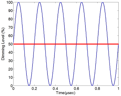
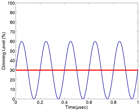
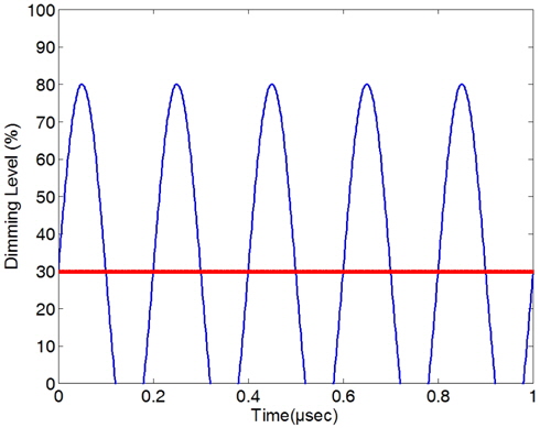
    OFDM signals are bipolar with respect to the average, which is normally zero. Because VLC offers only nonnegativity, the average should be moved to a positive value. This average value becomes the required dimming level of the lighting. Clipping is inevitable in OFDM, and it is more severe when the dimming target is very low (near zero) or high (near the maximum intensity), because the signals should be within [0, A], where A is the maximum intensity. In this paper, dimming is represented by normalization to the maximum intensity. Dimming of 100% means the transmission is the maximum intensity. As shown in Fig. 3, when the dimming target is 50% the upper and lower spaces are equal and maximized evenly, and the effect of clipping is minimized. On the other hand, the dimming target cannot be adjusted because it is a user constraint. For dimming less than 50% low-end clipping is likely to occur, while high-end clipping is predicted for a higher dimming. If the aim is to avoid or reduce degradation by clipping, one solution would be to decrease the amplification of the OFDM signals around the average level. Figure 4 shows limited amplification to combat clipping, but this creates another obstacle, in that the influence of noise is increased. In contrast to Fig. 4, Fig. 5 shows a clipped signal that is more robust to noise. Therefore, there is some trade-off between clipping and signal quality.

    The channel quality of VLC under additive Gaussian noise with the standard deviation, σ, is expressed as the maximum-intensity-to-noise ratio (A/σ). At a fixed A/σ, more amplification results in more clipping. In contrast, less amplification reduces clipping, but the vulnerability to noise is increased. Therefore, amplification can be adjusted for the performance enhancement by some trade-off. In the following section, the optimal amplification is derived from a simulation to reduce the BER, depending on the channel quality and dimming.

    III. SIMULATION RESULTS

    3.1. Simulation Environments

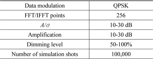
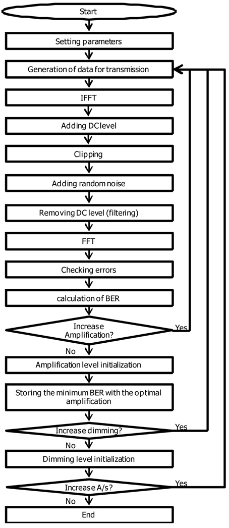
    The simulation parameters are given in Table 1. At a transmitter, a series of random data is generated and trans formed to an OFDM signal by IFFT. The amplification and shift for dimming are applied, followed by clipping. Clipping prevents overheating, to avoid either degradation of the output light or total failure [46]. The channel quality A/σ ranges from 10 dB to 30 dB in the simulation. Here amplification means the difference of the signal amplitude from the dimming level, which is defined as the root-mean-square of the signal divided by σ. Note that energy consumption is constant regardless of the level of amplification; the dimming determines the energy consumption. Figure 6 shows the simulation flowchart. If the dimming target d is less than 50%, the result for d is the same as that for (100%-d ). This can be explained as follows: The signal x(t) with dimming d has the same clipping degradation as the signal -x(t) with dimming (100%-d ), where the DC levels are not applied to the signals. The two signals correspond to X(f ) and -X(f ) following a Fourier transform. Because typical data-modulation schemes such as QPSK and QAM yield symmetrical constellations with respect to the horizontal axis, the OFDM data for X(f ) and -X(f ) occur with equal probability from random data generation. This means that the results for dimmings d and (100%-d ) are statistically identical. Therefore, the results for just 50-100% dimming are sufficient, and these are obtained from the simulation.

    [TABLE 1.] Simulation parameters

    label

    Simulation parameters

       3.2. Results

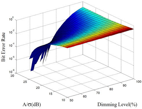
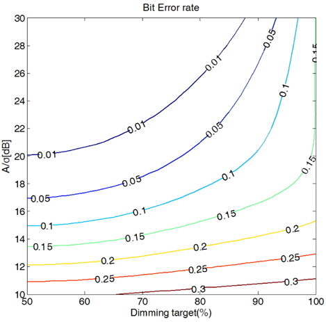
    Figure 7 shows the best BER obtained for a given channel quality and dimming. The BER changes depending on the amplification, and the best BER and the corresponding optimal amplification are obtained after an exhaustive search. For a given A/σ and dimming, the BER is obtained by a Monte Carlo simulation for each amplification value. The minimum BER then accompanies the optimal amplification. This process is repeated for further A/σ and dimming values. Figure 8 shows the contour graph for Fig. 7. With the criterion of 10-2 BER, the upper left region over the contour line for 0.01 is preferable in the figure.

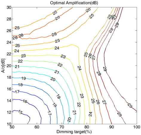
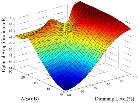
    Figure 9 shows the optimal amplification for Fig. 7, and Fig. 10 presents the contour representation of Fig. 9. For 50% dimming, the channel quality and optimal amplification increase linearly when the channel quality is less than 25 dB, where the effects of noise and clipping are balanced. For high channel quality, noise becomes negligible. Therefore, reduced clipping results in no further amplification. High-end clipping always occurs for approximately 100% dimming. Because more amplification toward a lower direction reduces the effects of noise, the optimal amplification increases. Note that the simulation is performed for an amplification of 10-30 dB.

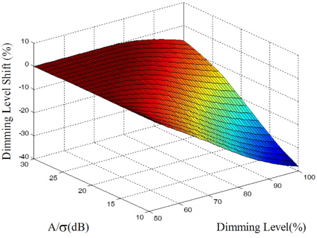
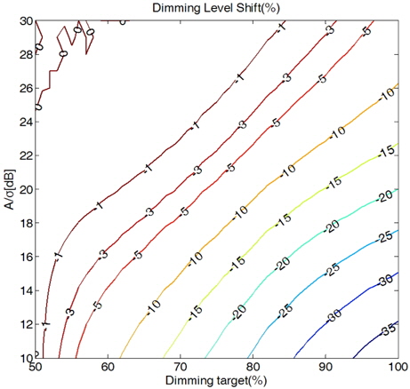
    In addition, uneven clipping yields a change in the average of the signals, and a shift in dimming follows. This is a critical problem for user demand of the requested dimming level. More uneven clipping induces a further shift in the resulting dimming. Figure 11 shows the resulting shifts, and Fig. 12 shows the contour representation of Fig. 11. A smaller A/σ with a higher dimming target incurs a greater shift in dimming. Note that 50% dimming produces no shift in dimming. As an extreme example, for a dimming target of 1% the error is 100% if clipping results in 2% dimming. Therefore, the shift of dimming by clipping should be considered carefully for OFDM systems in dimmable VLC, particularly for low dimming targets.

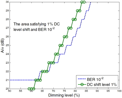
    Figure 13 shows the region where the BER is less than 10-2 and the shift in dimming is less than 1%. OFDM is not a suitable option with A/σ < 21 dB, and dimming of greater than 63% is unacceptable with A/σ = 21 dB.

    IV. CONCLUSION

    This paper reports the optimal amplification and BER depending on the channel quality and dimming target in VLC OFDM systems. In addition, a shift in the resulting dimming caused by uneven clipping is observed. With the restrictions of 10-2 BER and a 1% dimming shift, OFDM is not preferable with A/σ < 21 dB, and more than 63% dimming is unacceptable with A/σ = 21 dB. OFDM is a candidate for VLC with 85% dimming only when an A/σ value of at least 30 dB can be guaranteed.

참고문헌
  • 1. Schubert E. F., Kim J. K. 2005 “Solid-state light sources getting smart,” [Science] Vol.308 P.1274-1278 google cross ref
  • 2. Komine T., Nakagawa M. 2004 “Fundamental analysis for visible-light communication system using LED lights,” [IEEE Trans. Consum. Electron.] Vol.50 P.100-107 google cross ref
  • 3. Elgala H., Mesleh R., Haas H. 2011 “Indoor optical wireless communication: Potential and state-of-the-art,” [IEEE Commun. Mag.] Vol.49 P.56-62 google
  • 4. 2011 IEEE Standard for Local and Metropolitan Area Networks-Part 15.7: Short-Range Wireless Optical Communication Using Visible Light, IEEE Standard 802.15.7-2011 google
  • 5. Minh H. L., O’Brien D., Faulkner G., Zeng L., Lee K., Jung D., Oh Y., Won E. T. 2009 “100-Mb/s NRZ visible light communications using a postequalized white LED,” [IEEE Photon. Technol. Lett.] Vol.21 P.1063-1065 google cross ref
  • 6. Minh H. L., O’Brien D., Faulkner G., Zeng L., Lee K., Jung D., Oh Y. 2008 “High-speed visible light communications using multiple-resonant equalization,” [IEEE Photon. Technol. Lett.] Vol.20 P.1243-1245 google cross ref
  • 7. Komine T., Lee J. H., Haruyama S., Nakagawa M. 2009 “Adaptive equalization system for visible light wireless communication utilizing multiple white LED lighting equipment,” [IEEE Trans. Wireless Commun.] Vol.8 P.2892-2900 google cross ref
  • 8. Wu F.-M., Lin C.-T., Wei C.-C., Chen C.-W., Huang H.-T., Ho C.-H. 2012 “1.1-Gb/s wite-LED-based visible light communication employing carrier-less amplitude and phase modulation,” [IEEE Photon. Technol. Lett.] Vol.24 P.1730-1732 google cross ref
  • 9. Lee K., Park H., Barry J. R. 2011 “Indoor channel characteristics for visible light communications,” [IEEE Commun. Lett.] Vol.15 P.217-219 google cross ref
  • 10. Zeng L., O’Brien D. C., Minh H. L., Faulkner G. E., Lee K., Jung D., Oh Y., Won E. T. 2009 “High data rate multiple input multiple output (MIMO) optical wireless communications using white LED lighting,” [IEEE J. Sel. Areas Commun.] Vol.27 P.1654-1662 google cross ref
  • 11. Dambul K. D., O’Brien D. C., Faulkner G. 2011 “Indoor optical wireless MIMO system with an imaging receiver,” [IEEE Photon. Technol. Lett.] Vol.23 P.97-99 google cross ref
  • 12. Elgala H., Mesleh R., Haas H. 2009 “Indoor broadcasting via white LEDs and OFDM,” [IEEE Trans. Consum. Electron.] Vol.55 P.1127-1134 google cross ref
  • 13. Vu?i? J., Kottke C., Nerreter S., Buttner A., Langer K.-D., Walewski J. W. 2009 “White light wireless transmission at 200+ Mb/s net data rate by use of discrete-multitone modulation,” [IEEE Photon. Technol. Lett.] Vol.21 P.1511-1513 google cross ref
  • 14. Neokosmidis I., Kamalakis T., Walewski J. W., Inan B., Sphicopoulos T. 2009 “Impact of nonlinear LED transfer function on discrete multitone modulation: Analytical approach,” [J. Lightwave Technol.] Vol.27 P.4970-4978 google cross ref
  • 15. Haigh P. A., Ghassemlooy Z., Papakonstantinou I. 2013 “1.4-Mb/s white organic LED transmission system using discrete multitone modulation,” [IEEE Photon. Technol. Lett.] Vol.25 P.615-618 google cross ref
  • 16. Mesleh R., Elgala H., Haas H. 2012 “LED nonlinearity mitigation techniques in optical wireless OFDM communication systems,” [IEEE/OSA J. Opt. Commun. Netw.] Vol.4 P.865-875 google cross ref
  • 17. Ha Y., Chung W. 2013 “A feedforward partial phase noise mitigation in the time-domain using cyclic prefix for COOFDM systems,” [Journal of the Optical Society of Korea] Vol.17 P.467-470 google cross ref
  • 18. Azhar A. H., Tran T.-A., O'Brien D. 2013 “A Gigabit/s indoor wireless transmission using MIMO-OFDM visible-light communications,” [IEEE Photon. Technol. Lett.] Vol.25 P.171-174 google cross ref
  • 19. Ntogari G., Kamalakis T., Walewski J. W., Sphicopoulos T. 2011 “Combining illumination dimming based on pulse-width modulation with visible-light communications based on discrete multitone,” [IEEE/OSA J. Opt. Commun. Netw.] Vol.3 P.56-65 google cross ref
  • 20. Popoola W. O., Poves E., Haas H. 2013 “Error performance of generalized space shift keying for indoor visible light communications,” [IEEE Trans. Commun.] Vol.61 P.1968-1976 google cross ref
  • 21. Wang Z., Zhong W.-D., Yu C., Chen J., Francois C. P. S., Chen W. 2012 “Performance of dimming control scheme in visible light communication system,” [Opt. Express] Vol.20 P.18861-18868 google cross ref
  • 22. Cho E., Choi J.-H., Park C., Kang M., Shin S., Ghassemlooy Z., Lee C. G. 2011 “NRZ-OOK signaling with LED dimming for visible light communication link,” [Proc. 16th Eur. Conf. Netw. Opt. Commun.] P.32-35 google
  • 23. Jang H.-J., Choi J.-H., Ghassemlooy Z., Lee C. G. 2012 “PWM-based PPM format for dimming control in visible light communication system,” [Proc. 8th Int. Symp. Commun. Syst., Netw. Digital Signal Process] P.1-5 google
  • 24. Grubor J., Randel S., Langer K.-D., Walewski J. W. 2008 “Broadband information broadcasting using LED-based interior lighting,” [J. Lightwave Technol.] Vol.26 P.3883-3892 google cross ref
  • 25. Bai B., Xu Z., Fan Y. 2010 “Joint LED dimming and high capacity visible light communication by overlapping PPM,” [Proc. 19th Annu. Wireless Opt. Commun. Conf.] P.1-5 google
  • 26. Rajagopal S., Roberts R. D., Lim S.-K. 2012 “IEEE 802.15.7 visible light communication: Modulation schemes and dimming support,” [IEEE Commun. Mag.] Vol.50 P.72-82 google
  • 27. Yoo J.-H., Jung S.-Y. 2013 “Modeling and analysis of variable PPM for visible light communications,” [EURASIP J. Wireless Commun. Netw.] Vol.2013 P.134 google cross ref
  • 28. Anand M., Mishra P. 2010 “A novel modulation scheme for visible light communication,” [Proc. Annu. IEEE India Conf.] P.1-3 google
  • 29. Moon H.-D., Jung S.-Y. 2012 “Multi-coded variable PPM for high data rate visible light communications,” [Journal of the Optical Society of Korea] Vol.16 P.107-114 google cross ref
  • 30. Lee K., Park H. 2011 “Modulations for visible light communications with dimming control,” [IEEE Photon. Technol. Lett.] Vol.23 P.1136-1138 google cross ref
  • 31. Kwon J. K. 2010 “Inverse source coding for dimming in visible light communications using NRZ-OOK on reliable links,” [IEEE Photon. Technol. Lett.] Vol.22 P.1455-1457 google cross ref
  • 32. Ahn K.-I., Kwon J. K. 2012 “Capacity analysis of M-PAM inverse source coding in visible light communications,” [J. Lightwave Technol.] Vol.30 P.1399-1404 google cross ref
  • 33. Siddique A. B., Tahir M. 2011 “Joint brightness control and data transmission for visible light communication systems based on white LEDs,” [Proc. IEEE Consum. Commun. Network. Conf.] P.1026-1030 google
  • 34. Kim J., Lee K., Park H. 2012 “Power efficient visible light communication systems under dimming constraint,” [Proc. 23rd IEEE Int. Symp. Pers. Indoor Mobile Radio Commun.] P.1968-1973 google
  • 35. Das P., Kim B.-Y., Park Y., Kim K.-D. 2012 “A new color space based constellation diagram and modulation scheme for color independent VLC,” [Adv. Electr. Comput. Eng.] Vol.12 P.11-18 google cross ref
  • 36. Bai B., He Q., Xu Z., Fan Y. 2012 “The color shift key modulation with non-uniform signaling for visible light communication,” [Proc. 1st IEEE Int. Conf. Commun.] P.37-42 google
  • 37. Ahn K.-I., Kwon J. K. 2012 “Color intensity modulation for multicolored visible light communications,” [IEEE Photon. Technol. Lett.] Vol.24 P.2254-2257 google cross ref
  • 38. Suh Y., Ahn C.-H., Kwon J. K. 2013 “Dual-codeword allocation scheme for dimmable visible light communications,” [IEEE Photon. Technol. Lett.] Vol.25 P.1274-1277 google cross ref
  • 39. Kim S., Jung S.-Y. 2011 “Novel FEC coding scheme for dimmable visible light communication based on the modified Reed-Muller codes,” [IEEE Photon. Technol. Lett.] Vol.23 P.1514-1516 google cross ref
  • 40. Kim S., Jung S.-Y. 2013 “Modified RM coding scheme made from the bent function for dimmable visible light communications,” [IEEE Photon. Technol. Lett.] Vol.25 P.11-13 google cross ref
  • 41. Lee S. H., Kwon J. K. 2012 “Turbo code-based error correction scheme for dimmable visible light communication systems,” [IEEE Photon. Technol. Lett.] Vol.24 P.1463-1465 google cross ref
  • 42. Lee S. H., Ahn K.-I., Kwon J. K. 2013 “Multilevel transmission in dimmable visible light communication systems,” [J. Lightwave Technol.] Vol.31 P.3267-3276 google cross ref
  • 43. Lee S. H., Kwon J. K. 2013 “Distributed dimming control for LED lighting,” [Opt. Express] Vol.21 P.A917-A932 google cross ref
  • 44. Ohtsuki T. 2003 “Multiple-subcarrier modulation in optical wireless communications,” [IEEE Commun. Mag.] Vol.41 P.74-79 google
  • 45. Armstrong J., Lowery A. J. 2006 “Power efficient optical OFDM,” [Electron. Lett.] Vol.42 P.370-372 google cross ref
  • 46. Elgala H., Mesleh R., Haas H. 2010 “An LED model for intensity-modulated optical communication systems,” [IEEE Photon. Technol. Lett.] Vol.22 P.835-837 google cross ref
OAK XML 통계
이미지 / 테이블
  • [ FIG. 1. ]  Block diagram of OFDM for VLC.
    Block diagram of OFDM for VLC.
  • [ FIG. 2. ]  Complex-conjugate data mapping.
    Complex-conjugate data mapping.
  • [ FIG. 3. ]  Signal for 50% dimming. A practical OFDM signal is the sum of such sinusoidal waves with different frequencies.
    Signal for 50% dimming. A practical OFDM signal is the sum of such sinusoidal waves with different frequencies.
  • [ FIG. 4. ]  Signal with limited amplification for 30% dimming.
    Signal with limited amplification for 30% dimming.
  • [ FIG. 5. ]  Low-end clipping for 30% dimming.
    Low-end clipping for 30% dimming.
  • [ TABLE 1. ]  Simulation parameters
    Simulation parameters
  • [ FIG. 6. ]  Simulation flowchart.
    Simulation flowchart.
  • [ FIG. 7. ]  Best BER, depending on A/σ and dimming.
    Best BER, depending on A/σ and dimming.
  • [ FIG. 8. ]  Contour graph for the best BER.
    Contour graph for the best BER.
  • [ FIG. 9. ]  Optimal amplification, depending on A/σ and dimming.
    Optimal amplification, depending on A/σ and dimming.
  • [ FIG. 10. ]  Contour graph for the optimal amplification.
    Contour graph for the optimal amplification.
  • [ FIG. 11. ]  Dimming level shifts for the optimal amplification, depending on A/σ and dimming.
    Dimming level shifts for the optimal amplification, depending on A/σ and dimming.
  • [ FIG. 12. ]  Contour graph for the dimming level shifts.
    Contour graph for the dimming level shifts.
  • [ FIG. 13. ]  Acceptable region satisfying 10-2 BER and a 1% dimming level shift.
    Acceptable region satisfying 10-2 BER and a 1% dimming level shift.
(우)06579 서울시 서초구 반포대로 201(반포동)
Tel. 02-537-6389 | Fax. 02-590-0571 | 문의 : oak2014@korea.kr
Copyright(c) National Library of Korea. All rights reserved.