Environmental changes, especially global climate change, are creating new routes to reduce a shipping service distance in Arctic area. The Arctic routes are shorter than 60% of existing ways Panama or Suez canal). For this reason, ship owners prefer to navigate in Arctic area and a transportation of goods though the Arctic area is increasing. But the low temperature in Arctic condition changes the material properties. Especially, the material will be brittle and strength will increase. And an ultimate strength analysis of ship stiffened panels is changed depending on temperatures. In present study, the ultimate strength analysis of stiffened panels in double hull oil tankers is performed under various low temperatures with the material properties obtained by tensile coupon test. The analytical method as named ALPS/ULSAP was used for analysis method and 6 kinds of temperature (20, 0, −20, −40, −60 and −80℃) were considered to investigate the effect of Arctic conditions.
지속되는 지구온난화로 인해 극 지역의 결빙 면적이 감소하면서 북극 항로에 대한 관심이 높아지고 있다. 북극해항로(Northern Sea Route, NSR) 와 북서항로(northwest route) 를 이용하면 기존 항로에 비해 수송 거리 및 수송 소요 시간이 단축되고, 이는 더 많은 경제적 이익을 창출할 뿐 아니라, 연료의 사용량을 줄이며, 온실 가스인 CO2 배출 감소에도 기여한다. 이러한 북극항로의 경제적, 환경적 이점들로 인해 북극항로를 항해할 수 있는 신조선박 설계 및 기존선박의 운용가능성에 대한 검토가 필요하다
이러한 선박은 극지환경에 노출되며, 극지환경에 대한 구조물의 안전성 평가가 필수로 요구된다. 특히, 재료적 특성 관련한 연구 (Park, et al., 2012; Min, et al., 2011; Park, et al., 2011)는 많이 수행되어져 왔고, 선박 구조물 (판, 보강판, 선각) 의 구조강도 대한 상온 상태에서의 최종강도 특성, 초기처짐 영향, 붕괴특성특성에 관련한 다양한 연구가 되어왔다 (Paik, et al., 2008; Paik & Seo, 2009a; 2009b; Paik, et al., 2011; Kim, 2012; Park, et al., 2007; Choung, et al., 2011; Yim, et al., 1981; Lee, 1985). 그러나 선체 구조강도에 대한 저온 특성 효과에 관한 연구는 부족하며, 극지 운항을 하기 위한 선박의 설계 기준을 위해서 극지환경을 고려한 선박의 최종강도 특성 규명이 이루어져야 한다. 본 연구에서는 저온 환경 하에서의 선박을 이루는 기본적인 부재인 선체 보강판의 최종강도 규명을 위한 연구를 수행하였다. 이는 실제 구조물이 자신의 임무를 더 이상 수행할 수 없는 한계상태 설계기법으로서, 신뢰성 있고 경제적 측면에서 더욱 타당한 설계를 가능하게 해준다 (Paik & Thayamballi, 2003). 본 연구에서는 다양한 선종의 보강판의 압축 최종강도를 평가하고자, 해석적 방법인 ALPS/ULSAP(Analysis of Large Plated Structures / Ultimate Limit State Assessment Program) 을 이용하였으며, 이를 상온 (20℃) 에서의 값과 비교 분석을 하였다.
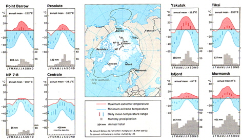
저온 환경에서 선체 보강판의 최종강도를 평가하기 위해 저온 환경을 선정하였다. Fig. 1 에서 북극지역의 연간 온도 분포를 나타내고 본 연구에서는 이를 토대로 상온 (R.T.: 20℃) 에서 −80℃ 까지의 온도를 해석 범위로 선정하였다. 일반적으로 선박에 주로 사용되는 AH32 강재와 저온용 강재로 알려진 DH32 강재를 대상재료로 선정하였다.
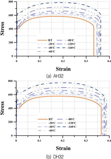
최근 ASTM (2004) 및 ISO (2000) 을 따른 저온 재료 인장시험을 통해 AH32 와 DH32 강재의 재료특성을 수행하였다 (Park, et al., 2012). Fig. 2는 공칭 응력 - 변형률 선도를 나타내고, 본 연구에서는 실험결과를 바탕으로 보강판 최종강도 계산을 위한 AH32, DH32 강재의 항복응력 값을 보간법을 통하여 정의하였다
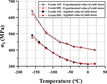
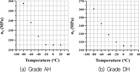
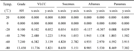
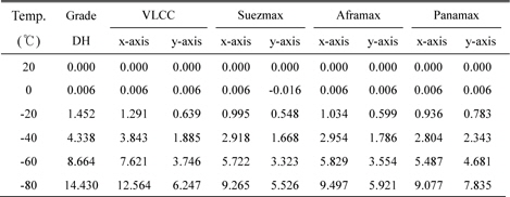
항복응력 값은 실제 시험에서 얻어진 항복응력을 고장력 강재의 최소요구치인 315MPa 으로 보정해준 뒤 각 온도에서의 항복응력 값을 구하였다. Fig. 3 에서는 실제 실험결과와 보정된 항복응력 값을 보여준다.
Fig. 4 에서 AH 강재와 DH 강재 모두 온도가 감소함에 따라 재료의 항복응력이 증가하는 것을 알 수 있다. 두 강재 모두 비슷한 경향으로 증가하고, AH 강재의 경우 −40℃ 부터 항복 응력이 증가하기 시작하지만, DH 강재는 AH 강재와는 다르게 −20℃ 부터 항복응력이 증가하는 것을 알 수 있다.
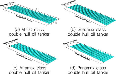
기존 운항중인 선박이 북극항로 운항 시, 선박의 최종한계상태 기준 운항가능성 분석을 위하여 다양한 선종에 대한 검토가 필요하다. 이에 본 연구에서는 세계 물동량에 주요한 부분을 차지하는 VLCC, Suezmax, Aframax 그리고 Panamax 급 이중 선체 유조선의 보강판을 고려하였다.
선박의 종굽힘모멘트가 작용하는 하중상태인 새깅(sagging) 및 호깅(hogging) 상태에 대한 압축력이 작용하는 갑판부의 보강판과 선저부의 보강판을 검토해야한다. 그러나 저온 환경 하에서의 흘수 아래 부분의 구조물은 해수의 특성상 저온 영향을 받지 않으므로, 극저온 환경에 노출 되기 쉬운 갑판부의 보강판을 대상 구조물로 선정 하였다.
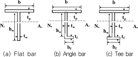
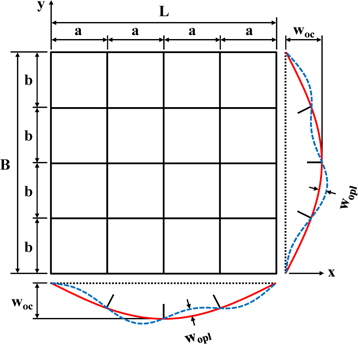
Fig. 5 는 본 연구에 사용된 보강판의 형상을 보여주며, Fig. 6과 Table 1은 해당되는 보강판의 보강재 형상 및 치수를 보여준다. 실제 선박의 경우 갑판부의 판두께는 위치 별로 다르기 때문에, Table 1 의 tp 는 등가두께를 적용 하였다.
[Table 1] Dimensions of stiffened panels on deck of double hull oil tankers
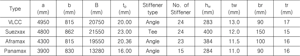
Dimensions of stiffened panels on deck of double hull oil tankers
본 연구에서는 보강판의 최종강도 해석에 ALPS/ULSAP (2013) 프로그램을 사용하였다. ALPS/ULSAP은 설계공식을 이용한 판 및 보강판의 최종강도 해석프로그램으로, 그 정확성은 범용 비선형 유한요소 해석 프로그램과 비교 연구를 통해 이미 입증 되었다 (Paik, at al., 2010).
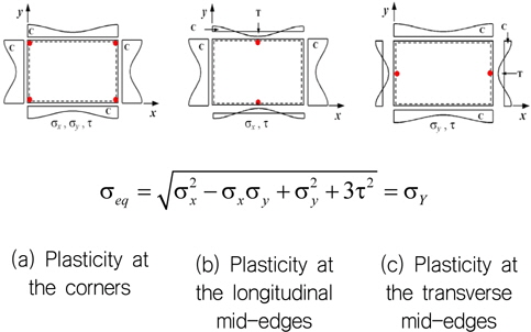
ALPS/ULSAP 은 해당 구조물이 판재일 경우와 보강판일 경우를 고려하여 다른 설계 공식을 이용하게 되는데, 우선 판의 최종 강도 해석을 위해서는 Fig. 7 에서 보는 바와 같이 세가지 경우로 나누어서 계산한다.
첫째, 판의 네 모서리에서 소성이 일어나는 경우, 둘째 길이방향 중앙부의 양 끝단에서 소성이 일어나는 경우 그리고 폭 방향 중앙부의 양 끝단에서 소성이 일어나는 경우이다. 각각의 경우 von-Mises 식을 기초로 하여 산정되며, 이 중 가장 작은 값을 해당 판의 최종강도라고 평가한다.
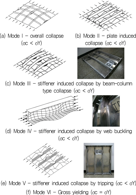
또한 ALPS/ULSAP 은 보강판의 최종강도를 계산하기 위해 6 가지의 붕괴모드를 나누어 계산하여 이중 가장 작은 값을 보강판의 최종강도라고 정의한다. Fig. 8 은 ALPS/ULSAP 에서 나타나는 보강판의 6가지 붕괴모드를 보여주고 있다.
[Fig. 8] Collapse modes for calculating the ultimate strength of stiffened panels (Paik & Kim, 2002)

Mode I 은 보강재의 치수가 작아서 보강재와 판재 모두 붕괴되는 현상이고, Mode II 는 판에 의한 붕괴로서, 2축 압력이 작용할 때 판재만 붕괴되는 현상이다. Mode III - V 는 보강재에 의한 붕괴로, Mode III 는 Perry-Robertson 식에 의거하여 보강판이 Beam-column 형태로 붕괴되고, Mode IV 는 보강재의 웨브에 좌굴이 일어나는 붕괴형태, 보강재가 옆으로 누워버리는 tripping 현상이 발생하는 Mode V, 그리고 전단면 소성에 의해 붕괴되는 Mode VI 이 있다.
모든 구조물은 제작 시 용접으로 발생하는 용접 잔류 응력과 초기 처짐이라는 결함을 가지고 있다. 보강판의 최종강도 해석을 위해서는 반드시 이 초기 결함을 고려해야 하며, 특히 초기 처짐은 재료의 기하학적 비선형성에 있어서 큰 영향을 주는 요인이다.
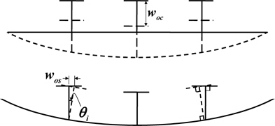
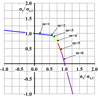
본 연구에서 고려된 초기 처짐으로는 판의 초기 처짐(buckling mode initial deflection) 및 보강재의 초기 처짐(volumn type and sideways initial distortion) 이 있다. Fig. 9 는 판, Fig. 10 은 보강재에 생기는 초기 처짐의 형상을 보여주고 있다. Eqs. (1) & (2) 는 판과 보강재의 처짐에 대한 공식을 나타낸다. 또한 최종강도 계산을 위해 Fig. 11 에서 보강판에 작용하는 하중 비에 따른 좌굴 반파수의 관계를 보여주고 있다. 네 끝단 단순지지를 받는 판의 하중 비에 따른 좌굴 반파수를 계산하는 Eq. (3) (Paik & Thayamballi, 2003) 을 이용하여 하중 비에 따른 좌굴 반파수를 다양한 대상선박에 대하여 적용하였다.
wopl 는 판의 초기처짐, woc 는 Column type 의 보강재의 처짐, wos 는 Sideways type 의 보강재의 처짐, m 은 판의 좌굴 반파수를 의미한다. 그리고 판 세장비와 두께에 따른 함수로 판의 처짐을 이용하여, 선종 별 보강판의 초기 처짐을 적용하였다 (ISO, 2007).
본 연구에서는 용접에 의한 용접 잔류 응력은 고려되지 않았다

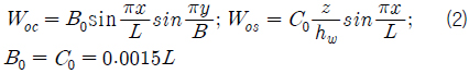
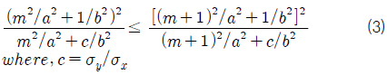
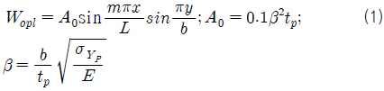
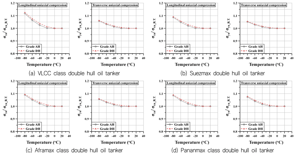
Fig. 12 는 선종 별 이중 선체 유조선의 갑판 보강판이 2축 압축 하중을 받을 때 각 온도에 따른 강재 별 최종강도를 보여주고 있다. 각 온도에서의 최종강도를 비교 하기 위해 σeq 값을 상온에서의 값으로 동일하게 사용하였다. 네 선종 모두 저온으로 갈수록 최종강도가 증가하는 것을 볼 수 있는데, 이는 재료의 항복 강도가 저온으로 갈수록 높아지기 때문이다. 그리고 폭 방향 압축 하중의 크기가 길이방향 압축 하중의 크기보다 상대적으로 온도의 영향을 적게 받는다는 것을 알 수 있다. 강재의 Grade 별 보강판의 길이 방향 및 폭 방향 최종강도의 증가율을 Fig. 13 에 나타내었다.
AH32 강재와 DH32 강재를 사용하였을 때 모두 온도가 낮아짐에 따라 최종강도가 증가하는 것을 확인 할 수 있으며, DH 강재가 AH 강재보다 좀 더 큰 증가율을 보임을 알 수 있다.
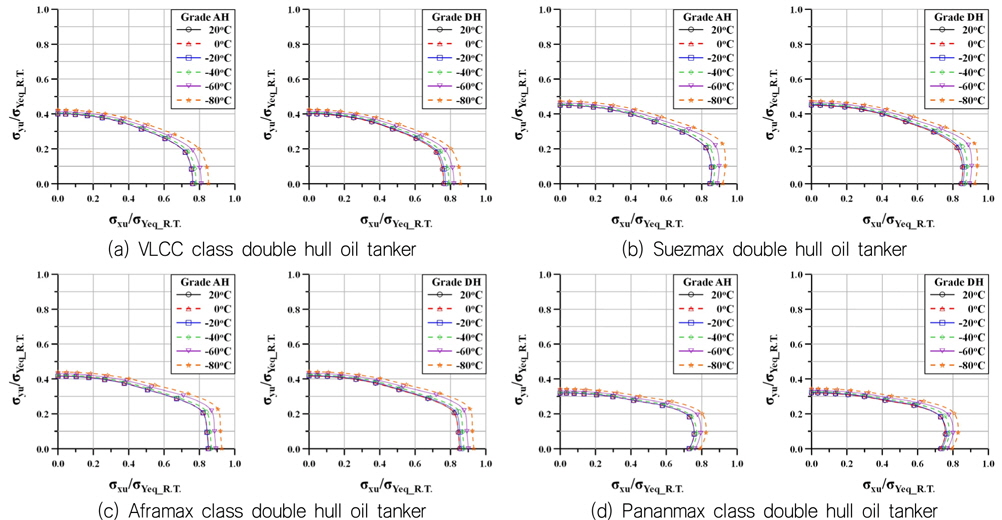
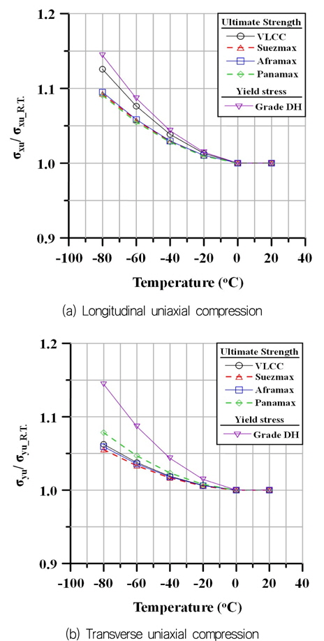
Figs. 14 & 15 은 길이 방향과 폭 방향 1축 압력 작용 시 온도 변화에 따른 최종 강도 증가율을 상온 일 때의 최종강도를 기준으로 나타내고 있다. Figs. 14 & 15 에서 나타나듯이 보강판 최종강도 증가가 강재의 항복응력 증가를 따라가지 못하는 것을 알 수 있다. 실제로 보강판이 붕괴 될 때, 앞 절에 나온 바와 같이 붕괴모드를 따라가게 되는데, 보강판이 전체적이 아닌, 국부적으로 붕괴됨에 따라 그 최종강도를 평가하기 때문에, 온도에 따른 강재의 강도 증가가 구조물의 강도증가에 비례적으로 영향을 미치는 것이 아니라는 것을 보여준다.
선종 별 1축 압력 작용 시 온도에 따른 강재 종류 별 최종강도 증가에서 DH 강재가 AH 강재보다 더 높은 증가율을 보인 것의 영향으로 DH 강재를 사용하였을 때 온도에 따른 증가율이 더 높게 나온 것을 확인 할 수 있다. 폭 방향 압축 최종강도의 온도 별 증가율이 Panamax 의 보강판에서 가장 크게 나왔는데, 이는 길이방향 보강재의 영향을 적게 받는 폭 방향 압축 상황에서 판재의 최종강도 증가가 많은 영향을 받는 것을 볼 수 있는데, Table 1 에서 알 수 있듯이 다른 선종 보다 Panamax 의 판재의 두께가 가장 얇으면서 판의 길이방향 치수가 작기 때문에 온도에 영향을 더 크게 받는 것이라 사료된다.
Tables 2 & 3 에서 온도에 따른 강재의 항복 강도 증가율 및 선종 별 보강판 최종강도 증가율을 수치적으로 나타내었다.
[Table 2] Rate of increase of ultimate strength under uniaxial compression (unit : %)

Rate of increase of ultimate strength under uniaxial compression (unit : %)
[Table 3] Rate of increase of ultimate strength under uniaxial compression (unit : %)

Rate of increase of ultimate strength under uniaxial compression (unit : %)
본 연구에서는 저온에 영향을 받는 선체 보강판의 최종강도를 알아보기 위해 저온인장 시험을 통한 온도에 따른 재료의 물성치를 이용하여 극지운항 선박의 보강판 최종강도를 해석적 방법인 ALPS/ULSAP 을 사용하여 계산하였다. 대상 구조물로는 VLCC, Suezmax, Aframax 그리고 Panamax 급 이중 선체 유조선의 갑판부 보강판이며, 저온에 따라 최종 강도 변화를 알아 보았다. 본 연구를 통해 극지환경이 선체 보강판의 최종강도에 끼치는 영향에 대한 결론은 다음과 같다.
1) 온도가 감소함에 따라 재료의 항복 응력이 증가하고, 이에 따라 보강판의 최종강도 또한 증가한다. 하지만 온도가 감소함에 따른 보강판의 최종강도 증가율은 재료의 항복강도 증가율에 미치지 못한다. 2) 저온에 따른 재료의 항복 강도 증가가 구조물의 최종강도 증가에 비례적으로 영향을 미치지 않는다는 것을 보여준다. 이는 구조설계 시, 재료의 항복강도를 기준으로 실시하여선 안될 것이며, 한계상태 기반의 최종강도를 기준으로 설계 해야함을 보여준다. 3) 온도 별 길이 방향 압축 최종강도가 폭 방향 압축 최종강도 보다 더 민감하게 반응하는 것은 길이 방향으로 놓여진 보강재와의 상호 작용으로 보인다.
이러한 연구를 바탕으로 같은 재료의 후판과 박판이 온도 변화로 인해 생기는 물성치 변화에 대한 실험적인 연구를 수행해야 할 것이며, 수치적 방법으로 보강판의 최종강도를 평가하여 그 정도를 높여야 할 것으로 보인다.