We present a multi-tap microwave photonic filter with high selectivity through applying time-to-frequency mapping and optical frequency comb shaping techniques. When arranged in the time-to-frequency mapping stage, by a Fourier transform, the deviation of the optical taps to the target profile is significantly reduced while maintaining the apodization profile, resulting in high sidelobe suppression in the filters. By applying a simple time-to-frequency mapping stage to the conventional optical frequency combs, we demonstrate a substantially enhanced (>10dB) sidelobe suppression, resulting in filter lineshapes exhibiting a significantly high (>40dB) main lobe to sidelobe suppression ratio. These results highlight the potential of the technique for implementation in various passband filters with high sidelobe suppression.
The field of microwave photonics (MWP) exploits the wideband and low-loss capabilities of optics in order to enhance the performance of radio frequency (RF) systems [1, 2]. This perspective offers benefits that are otherwise unattainable with purely electronic solutions, such as ultra-broad bandwidth, insensitivity to electromagnetic interference, easy tuning, and programmability.
One of the promising applications of MWP is the implementation of filters for high-frequency carrier and broad bandwidth RF waveforms [1]. In contrast to the recent work on coherent filters [3], the most common implementation of MWP filters has been based on a delay-line multi-tap geometry, which is inspired by the design of finite-impulseresponse (FIR) digital filters [4]. Here, the optical source consists of an array of spectral lines. After being modulated by the RF signal to be filtered, sent to a dispersive medium, and photodetected, each optical tap provides a delayed and weighted copy of the input electrical signal.
A key attribute that is desirable in advanced RF filters is achieving broadband filters with high selectivity, which is manifested through large mainlobe-to-sidelobe suppression ratio (MSSR). This can be achieved through employing smooth, specifically shaped optical taps with minimal line-to-line amplitude variations, as demonstrated in [5]. With the increasing apodization preciseness of the optical taps, the MSSR of the filter response can be improved significantly [5].
The light sources that are considered in MWP filters include continuous-wave lasers [6], mode-locked lasers [7], and spectrally sliced broadband incoherent sources [8]. The spectral slicing enables a MWP filter with a large number of taps [8], but the stochastic nature of the optical source leads to limited noise performance [9]. Recently, delay-line MWP filters based on high-repetition-rate optical frequency combs (OFCs) [10] have been explored [11]; these are easy to scale to a high number of taps while providing optical frequency stability, flexibility in tuning, and a coherence level not attainable from other sources. However, the MSSRs of these light sources have been limited to the 30-35 dB level primarily due to the precision with which the light sources are apodized. In [5], a very high stopband attenuation of ~60 dB was achieved using the light source generated by a second order four wave mixing term. Although this enables a large MSSR, the light source exhibited an extremely large optical power decrease because it was based on a second order cascaded four wave mixing term [5]. It was also generated using a complex setup that includes two continuous-wave lasers, a highly nonlinear stage, and additional use of a band-pass filter to select the four wave mixing term.
In this letter, we significantly improve the smoothness and precision of the sources through adding a simple timeto- frequency (TTF) mapping stage to the conventional optical taps. The fluctuations in the frequency domain to the target profile primarily degrade the sidelobe of the signal in the time domain with significantly low signal shape change [5]. Through applying the TTF mapping stage to the signal, an optical spectrum that exhibits a considerably improved approximation to the target profile can be obtained, and this results in boosting the MSSR of MWP filters to ~45 dB level.
II. FLUCTUATION REDUCTION VIA TIME-TO-FREQUENCY MAPPING
Here, we present a simulation study that highlights the effect of the TTF mapping on the noise reduction of OFCs. Later, we experimentally demonstrate the MSSR improvement of the resulting MWP filter when using an OFC after applying the TTF mapping stage.
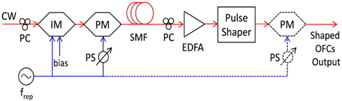
Once a strong, periodic, quadratically varying temporal phase has been introduced onto the periodic pulse, it undergoes TTF mapping [12, 13], resulting in optical spectra with similar shapes to the time domain intensity of the input waveform. Generating a periodic quadratic temporal phase is difficult; however, a sinusoidal temporal phase can be approximated using a quadratic function around its peak or its valley, and the first order provides a method of generating the required quadratic temporal phase. The sinusoidal temporal phase can be realized through a simply concatenated electrooptic phase modulator (EOPM) driven using a sinusoidal RF signal [13]. Through applying a large parabolic phase modulation via EOPM in every train period generated by the OFCs, the intensity shape is mapped into the spectral domain.
Figure 1 presents the schematic of the setup used to generate the OFCs. It is generated through cascading an intensity and phase modulator to a continuous wave laser. The bias point and phase shift are adjusted in order to provide a pseudo-flat-top envelope, and the repetition rate of the OFCs is governed by the 10 GHz clock source. Since the phase from the phase modulator has a quadratic profile, this can be compensated through applying a singlemode fiber (SMF; 900 meter) [14], which results in temporal signal compression to its bandwidth limited duration. After the polarization adjustment and amplification using a polarization controller and an Erbium doped fiber amplifier (EDFA), the comb is further apodized using a pulse shaper (Finisar Waveshaper 1000S), so that both sources have the same tap weights. By cascading the EOPM driven at its maximum RF input power (30 dBm), the shaped OFCs undergo TTF mapping.
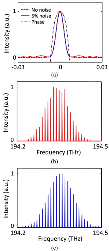
Here, we adopt the Gaussian shape spectrum having its own Fourier transform in order to provide a comparative study of the MSSR in the MWP filter links with the same filter shape. First, we implement the simulation based on the above schematic conditions in order to characterize the fluctuation improvements via the TTF mapping. Figure 2(b) presents an example of the simulated Gaussian OFCs before applying an EOPM (i.e. the components indicated by the dashed lines in Fig. 1 are not included). In Fig. 2(b), the coefficient of Gaussian and the standard deviation (SD) of the noise from the Gaussian target are assumed to be π and 5%, respectively. The Gaussian OFCs result in periodic Gaussian pulses in the time domain by Fourier transform. According to the simulation, the deviations of the OFCs from the target profile change the sidelobe shape of the Gaussian pulses with significantly low pulse shape changes in the time domain, as seen in Fig. 2(a) [5]. Through applying a quasi-quadratic phase via the EOPM indicated using the dashed lines of Fig. 1, the periodic Gaussian pulses with sidelobe fluctuations are converted into Gaussian OFCs whose number of side taps are slightly increased due to the sidelobe variation of the Gaussian pulses as seen in Fig. 2(c). This figure indicates ~0.5% SD of noise to the perfect Gaussian profile. According to our simulation, it also shows 0.8% and 0.3% SD of the noise after TTF mapping when the given noise is 7% and 3% SD, respectively.
III. HIGH STOPBAND ATTENUATION
Because the MSSR of the MWP filter is dependent on the apodization accuracy of the OFCs [5], we experimentally demonstrate the significant improvement of the MSSR when employing OFCs whose smoothness is considerably improved using the TTF mapping.
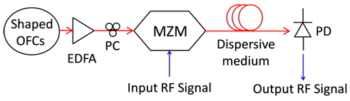
Figure 3 presents the schematic of the proposed MWP filter [4]. The shaped OFC generated using the setup in Fig. 1 is amplified and polarized by an EDFA and a polarization controller, respectively. Then, the light experiences optical double-sideband modulation, which is achieved using a Mach-Zehnder modulator biased at the quadrature point. The modulated light passes through a dispersion compensating fiber module with -1260 ps/nm dispersion at 1550 nm, resulting in a delay difference of 96 ps between adjacent 10 GHz spectral lines. After the photo-detection in a 20 GHz bandwidth photodiode, we measured the transfer function (S21 parameter) using a vector network analyzer.
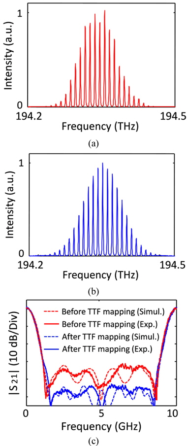
Figures 4(a) and 4(b) present the synthesized spectra measured using an optical spectrum analyzer. The two Gaussian-shaped spectra are apodized using the pulse shaper in order to maintain the same coefficient of the Gaussian spectrum after the TTF mapping. The OFC presented in Fig. 4(a) is the initially Gaussian-apodized spectra, and the OFC in Fig. 4(b) is the spectrum after applying the TTF mapping stage. As can be observed from Figs. 4(a) and 4(b), after applying the TTF mapping, the OFC provided significantly less noise (~0.65% SD) than the initial OFC (~5% SD), which is in excellent agreement with the simulated results presented in Figs. 2(b) and 2(c).
Figure 4(c) illustrates the measured (solid) and simulated (dashed) transfer functions of the MWP filters achieved when using the OFC with (blue) or without (red) the TTF mapping. The filter transfer function of the MWP filter can be written as follows:

where an is the power of the nth comb line, D is the fiber dispersion, and Δω is the repetition frequency of combs. The simulated transfer functions (dashed), which were obtained from Eq. (1) using the measure comb profile described in Figs. 4(a) and 4(b), exhibited ~32 dB (red dashed) and ~44 dB (blue dashed) MSSR, respectively. The measured responses closely matched the predicted ones in both cases, with MSSR values of ~31 dB (red solid) and ~43 dB (blue solid), respectively [5]. They also exhibited a free spectral range of 10.4 GHz, which is equal to the inverse of the 96 ps tap delay, and a bandwidth of ~390 MHz at 3 dB in the baseband.
In summary, we have demonstrated highly selective microwave photonic filters based on optical frequency comb shaping and time-to-frequency mapping. Using the Fourier transform properties of the Gaussian function, we implemented Gaussian-shaped combs in which the fluctuations were significantly low through application of a simple timeto- frequency mapping stage in the conventional Gaussianshaped combs, which resulted in highly suppressed sidelobes in the microwave photonic filters. The versatility of this scheme may be extended in order to achieve highly selective filters with various filter shapes and bandwidths through amplitude control of the combs via optical pulse shaping.