Noncontact 3-D surface reconstruction techniques have been extending their applications to various industrial fields such as medical, manufacturing and biometric areas. A large number of noncontact 3-D reconstruction techniques developed so far show their advantages and drawbacks as listed in [1]. Among them Moiré topography has been of prime interest because it provides fast operation for smooth surfaces since it was introduced [2-4]. For Moiré topography, when the projected grating of the projection system falls on the object, the deformed grating is generated on its surface, Moiré interference fringe patterns are then generated on the imaging system, yielding contours of the same heights expressed in wrapped phases. Due to diffraction, a virtual grating is often employed for replacing reference and/or projected gratings. Projection Moiré topography was thereafter developed to increase the resolution significantly using the virtual grating for the projection system. In the meantime, the phase shifting method has been devised to ensure repeatability of the projection Moiré topography where multiple phase shifts are carried out to easily calculate the phase map for objects [5, 6].
Although Moiré topography usually ensures fast and efficient 3-D reconstruction in smooth surfaces [7, 8], two big obstacles of noise and imperfect phase unwrapping make one hesitate to capitalize on this. To eliminate noise occurring in a wrapped phase map, cosine transform or wavelet transform has been tried [9-12]. The projection Moiré topography with phase shifting method provides simple and reliable wrapped phase images for objects with –π/2 to π/2 range, called 2π ambiguity, however it is very difficult to convert this wrapped phase to a noise free unwrapped phase map. Abrupt phase change more than π cannot be detected easily, so that very few techniques have been tried for achieving more exact phase unwrapping. The weighted least squares method with discrete cosine transform (DCT) was introduced and utilized where the least squares method was used for removing discontinuity (or noise) in the phase image and DCT was employed for phase unwrapping in a strict sense, however this method shows difficulty in tracking a sudden change of phase while unwrapping the wrapped phase image, and it requires huge computing power because of a large amount of computation [13].
In this work, the derivative Moiré topography by differentiating the wrapped phase map separately in x- and y-directions is proposed to resolve the 2π ambiguity problem. Compared with the least squares method with DCT, the proposed technique tracks sudden phase change very efficiently using the simple differentiation in x- and y-directions. This also does not introduce a large amount of computational burden, leading to very fast attainment of phase unwrapping.
II. THE PROPOSED MOIRE TOPOGRAPHY
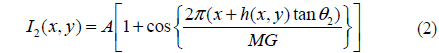
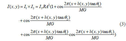
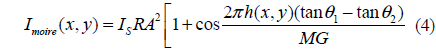
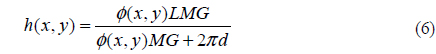
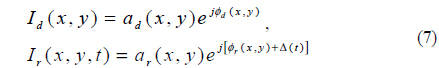
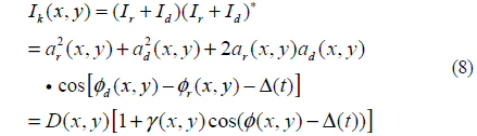
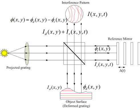
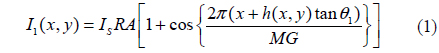
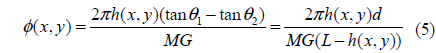
The classical measurement setup to obtain the Moiré fringe pattern using the phase shifting method is shown as illustrated in Figure 1 where


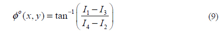
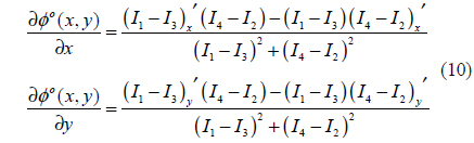
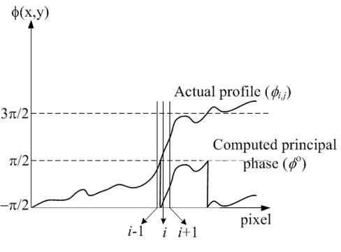
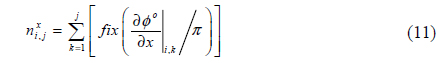
In this work, we perform the phase unwrapping by differentiating (9) twice in x- and y-directions, leading to (10) where a primed subscript means the differentiation with respect to the subscript. Since the derivative phases as expressed in (10) are continuous functions even around the big phase jump, phase can be tracked precisely without difficulty even if it is greater than 90º or less than -90º. The principal phase is at first calculated using (9) and then one differentiation is carried out in one direction (

The absolute Moiré order at the (
where

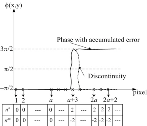
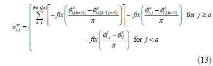
where the calculated phase from (12) may accumulate errors due to discontinuous contours. To resolve this error accumulation, phase compensation is carried out by calculating a different derivative with respect to wider step in the x-direction. Accumulated phase error is detected and incorrect phase becomes recovered by computation of intermediate order (

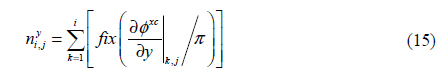
The absolute Moiré order is now calculated once more in the y-direction using (15),

Eventually the phase is unwrapped using (16),

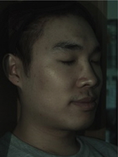
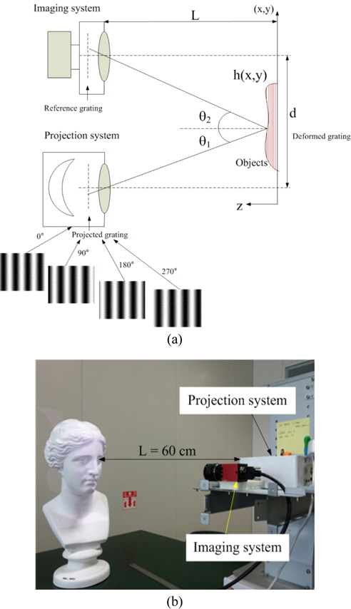
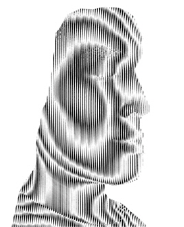
To validate the proposed method, a human face as shown in Fig. 5 is taken for an object which is located 60 cm away from the projection and imaging systems. The projection system used here has 1200×800 pixels and provides 28 cm×35 cm image to the plane 60 cm (
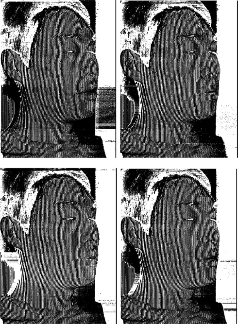
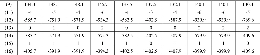
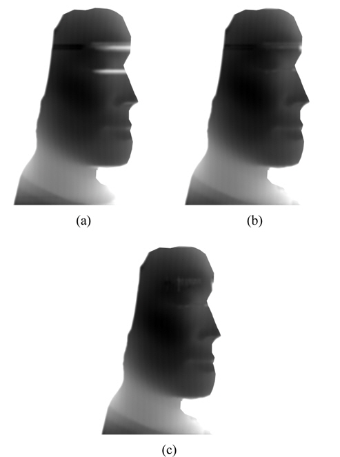
Figure 7 exhibits initial phase map obtained with (9) which shows the principal phase image from -90° to 90°. Figure 8(a) displays the unwrapped phase map applying the phase derivative in the x-direction, Fig. 8(b) shows the compensated phase map employing the additional derivative as introduced in (13), and Fig. 8(c) shows the finally unwrapped phase map which applied the phase derivatives in x- and y-directions as introduced in (10) to (16). Discontinuous contours due to overlapping two different heights and black spots lead to failure of phase unwrapping as shown in Fig. 8(c) where black spots provide errors in obtaining exactly unwrapped phase, as expected in Sec. II. A detailed procedure from (11) to (16) is offered for verification of the proposed method as displayed in Table 1 where phases before unwrapping are obtained from (9), and from these data the final unwrapped phases are successfully calculated using (11)-(16). The negative phases illustrate relatively lowered phases with respect to the highest altitude of cheek in Fig. 4.
[TABLE 1.] Results for phases and orders at 10 pixels between brows in Fig. 4

Results for phases and orders at 10 pixels between brows in Fig. 4
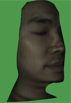
The final 3-D picture of a human face is reconstructed as illustrated in Fig. 9. For a clear view, the background image is removed and textured for vivid visualization. Finally a moving average with 50×50 window size is performed for removing ripples specifically around black spots such as eyebrow and nostril, providing smooth 3-D surface and adding a bit more CPU time. Vague stripes still appear on the cheek as seen in Fig. 9 since the light intensity of projected gratings are not perfectly sinusoidal, leading to some discontinuity for phase unwrapping.
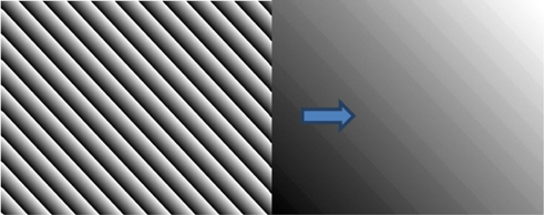
Compared with the least squares method with DCT, the proposed derivative Moiré technique shows fast computation and precise reconstruction for even a rough surface such as a human face. DCT has been applied to unwrap the phase image of the human face as taken in Fig. 5, however it does not produce the complete 3-D reconstruction. Therefore a very simple and periodic principal phase image was used to compare DCT and the proposed method as seen in Fig. 10. CPU times have been computed for three cases as summarized in Table 2, where the derivative Moiré topography shows much faster time taken for phase unwrapping.
[TABLE 2.] Comparison of two phase unwrapping methods in terms of CPU time
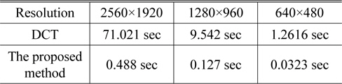
Comparison of two phase unwrapping methods in terms of CPU time
3-D reconstruction has been successfully implemented using the derivative Moiré topography based on phase unwrapping using differentiation of phase in x- and y-directions. Abrupt phase change is identified successfully by this method, leading to the precise and fast height computation of objects containing rough surfaces. Differentiation is performed both in x- and y-directions for obtaining noise free phase unwrapping. From this, errors occurring from inexact phase unwrapping are eliminated as the differentiation iterates. The classical phase shifting method is replaced by building four phase-shifted virtual reference gratings. A human face is exploited to validate the proposed method. This proposed method will provide a potential direction for systems necessitating robust and fast 3-D reconstruction.