The International Maritime Organization has determined that more than 80% of maritime accidents are caused by human error. A variety of methods have been considered to reduce maritime accidents caused by such human error. Navigators operate by observing surrounding maritime situations and analyzing information using various navigational devices. This study proposes a system to ensure safe navigation by assisting navigators through the delivery of maritime safety information (MSI) between land and sea. In the future, supplementing the system through long-term on-the-ship tests is necessary by defining MSI in relation to maritime service portfolio regions.
According to most statistics on domestic and foreign maritime accidents, the rate of accidents caused by human factors ranges from 60 to 80%. The International Maritime Organization (IMO) has reported that more 80% of maritime accidents are caused by human error [1, 2]. In Korea during the last five years, accidents caused by human factors account for 82% of all maritime accidents [3].
In modern ships, a variety of methods have been considered to reduce number of the maritime accidents caused by human error. Various types of navigational devices have been installed inside the bridges of ships. Navigators observe surrounding maritime situations and analyze other information obtained from these many navigational devices. However, because of worker fatigue caused by excessive work aboard high-speed ships, loading and unloading, and excessive paper work for ship operation, safe navigation is now threatened [4]. Therefore, technologies that aid navigator decision making have been proposed to reduce the numbers of accidents caused by human factors [5].
The IMO has been defined as an organization that harmoniously collects, integrates, exchanges, presentations, and analyzes maritime information at sea and seashore through electronic means. This vast information processing is designed to strengthen e-navigation and relevant services from port entry to departure and to ensure maritime safety and security as well as oceanic environmental protection. E-navigation, as an integrated and consistent system to reduce the workload of the bridge, essentially is an attempt to connect all systems [6, 7].
In this study, attempts are made to construct a system to fuse, display, and transmit maritime safety information (MSI) at land and sea in order to reduce the numbers of marine accidents.
MSI was first examined and a system to transmit and receive MSI at land and sea was designed. After test terminals were constructed, the effectiveness of the system was confirmed through transmission and reception tests at land and sea.
2. Maritime Safety Information
MSI originally referred to navigational and meteorological warnings, meteorological forecasts and distress alerts [8]. However, these original purposes haves recently been modified to mean navigational and meteorological warnings, meteorological forecasts and other urgent safety related messages broadcast to ships [9, 10]. These relevant services are defined the maritime service portfolio (MSP) of e-navigation shown in Table 1 [11].
[Table 1.] Maritime service portfolios (MSPs)
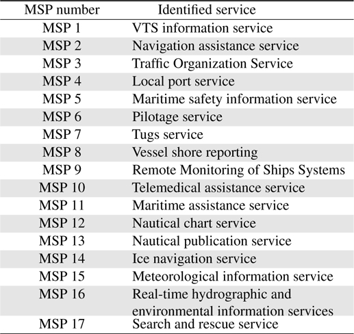
Maritime service portfolios (MSPs)
MSP describes operational and technical services and their associated levels of supplied by interested parties at a given sea area, waterway, or harbor. In addition, it includes services to the following regions [12]. - Port areas and approaches- Coastal waters and confined or restricted areas- Open seas- Areas outgoing offshore and/or infrastructureal development- Polar areas- Other remote areas.
The automatic identification system (AIS) is currently considered a means to transmit and receive MSI messages between land and sea. According to Safety Of Life At Sea Agreement, AIS must be installed on liners, vessels weighing more than 300 tons and used for international navigation. In addition, it has been extended to small ships by domestic law [13].
Ships transmit and receive various kinds of AIS messages using application-specific messages (AIS-ASM). Messages 1 through 3 are used to report a ship’s position, message 4 is used to report to base stations, messages 6 and 8 are used to transmit binary messages, which can contain any type of data. Research is currently in progress to introduce a new service based on AIS-ASM [14].
3. Design of an MSI Fusion System
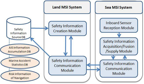
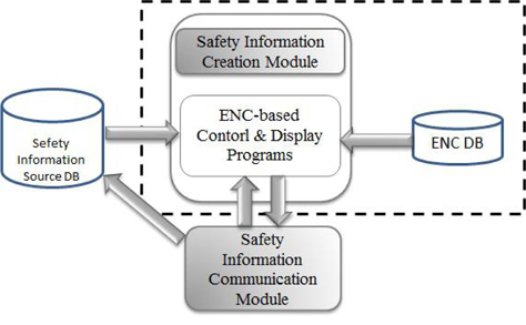
The objective of this research is to design and construct a fusion system for supply and transmission of MSI to assist navigator in decision making and to improve navigational safety. As shown in Figure 1, the system consists of land MSI and sea MSI subsystems, transmit and receive data between land and sea. This chapter describes the system and its module.
The land MSI system provides safety information based on information obtained from a safety information source database, and transmits it to the sea MSI system.
3.1.1 Safety information creation module
As shown in Figure 2, the safety information creation module is comprised of electronic navigation chart (ENC) control and display programs. It extracts and manages effective marine safety information from the safety information source database and transmits to sea. The module’s major functions are shown in Table 2.
[Table 2] Function of safety information creation module

Function of safety information creation module
3.1.2 Safety information communication module
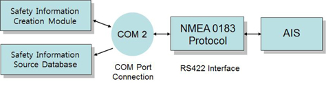
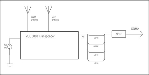
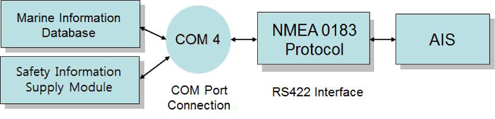
The safety information communication module is designed to perform two main reciprocal functions. First, it transmits to sea information acquired from the safety information creation module through AIS. Second, it delivers information received from sea to the safety information creation module and safety information source database. As shown in Figure 3, these methods of communication are accomplished according to the NMEA 0183 protocol by using an RS422 interface. NMEA 0183 has been used as the standard protocol for serial data communication of navigational devices since the 1980’s [15, 16]. As shown in the circuit diagram of Figure 4, the module is composed of an RS422 interface through an X9 port of a VDL 6000 Transponder.
The sea MSI system collects and analyzes real-time electronic data from navigational devices and then fuses and transmits that information. The system is comprised of an inboard sensor module for collecting electronic data, a safety information acquisition/fusion/supply module for processing, analysis, and fusion of acquired information, a safety information communication module for transmitting safety information to land and ships at sea.
For ships to navigate safely, effective communication between ships is essential. In order to construct a reliable system, electronic data collected from ships involved in actual sea navigation must employ similar navigational devices. For this purpose, device interface using navigational devices similar to those of actual merchant ships was designed for installation on Saenuri, a training ship of Mokpo Maritime University.
3.2.1 Inboard Sensor Module
Ships possess devices position, course, and speed, as well as devices for determining their locational relationship to other ships (using Radar, and AIS). In addition, they possess devices for devices for assessing weather conditions (wind speed, direction, and current), and devices for receiving safety information (through text broadcasting). The inboard sensor module was designed based on the operations of these several devices and the importance of MSI for safe navigation.
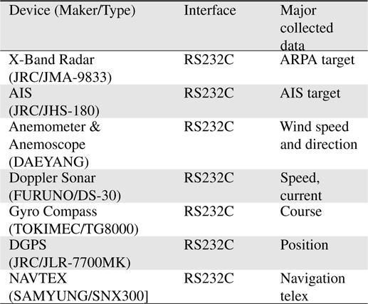
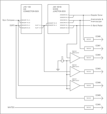
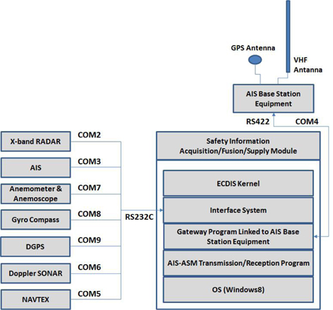
The navigation devices used to collect electronic data on the test ship Saenuri, are listed in Table 3. They were designed to connect with Radar and AIS for examining maritime situations involving Saenuri and other ships. In addition, the devices work in conjunction with Gyro Compass, DGPS, Anemometer & Anemoscope, and Doppler Sonar for interpreting onboard data, and NAVTEX for receiving safety information. However, because NAVTEX used by Saenuri is not supported by NMEA output, SNX300 of SAMYUNG ENC was separately installed. All seven devices communicate through NMEA 0183 protocol by using an RS232C interface.
[Table 3.] Interface devices and collected data of the inboard sensor module

Interface devices and collected data of the inboard sensor module
The circuit diagram of the inboard sensor module is shown in Figure 5. Because the many navigational devices on the training ship are connected to one another, if the electronic chart display & information system (ECDIS) and AIS use the interface box, they operate efficiently. ECDIS junction box are an X-Band Radar, Anemometer & Anemoscope, and Doppler Sonar, while interfaced with the AIS connection box, are the AIS, Gyro Compass, and DGPS. While the Radar, AIS, and Gyro compasses are used by many devices, because the levels of output signals are low, the signal strength is compensated for by adding a buffer.
3.2.2 Safety information acquisition/fusion/supply module
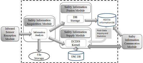
The safety information acquisition module analyzes initial information from interfaced devices. The analyzed results are first stored in files, and then delivered to the safety information fusion module and safety information supply modules.
The safety information fusion module stores information obtained from the maritime information database and if necessary, supplies the safety information supply module with past and statistical data.
The safety information supply module is composed of ECDIS kernels and displays the inboard sensor information received from the safety information acquisition module. If necessary, this module sends inquiries about information in maritime information database and uses that information in conjunction with statistics about low water areas, dangerous targets, and lighthouses from the ENC database (Figure 6).
3.2.3 Safety information communication module
The safety information communication module is designed to transmit through AIS both data acquired from the inboard sensors and data from the maritime information database to land and ships at sea. In addition, it receives data from land and sea. As shown in Figure 7, these methods of communication are accomplished according to NMEA 0183 protocol using the RS422 interface. Moreover, information received from land and ships at sea is delivered to the safety information supply module.
4. Construction and Test of the MSI Fusion System
4.1 Test Environment for the Land MSI System
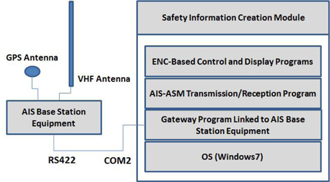
The test environment for the land MSI creation and supply system is shown in Figure 8. The safety information creation system and database are designed to use one terminal. In addition, the AIS-ASM transmission and reception program for data transmission and reception with installed to AIS base-station equipment through a linked gateway program.
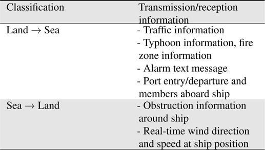
The information in the land MSI system that is to be exchanged with ships at sea is provided in Table 4. Traffic and important weather information such as that related to typhoons may be transmitted from land to sea, and, in turn, information related to marine traffic and weather condition may be received from ships at sea.

Transmission/reception information between land and sea for the land maritime safety information system
4.2 Test Environment for the Sea MSI System
Figure 9 displayed the test environment of the sea MSI system, installed on the bridge of the training ship Saenuri. The safety information acquisition/fusion/supply module is comprised of a single terminal and an ECDIS kernel and maritime information database. An AIS-ASM transmission and reception program for data transmission and reception with installed to AIS basestation equipment through liked gateway program. In addition, real-time information from seven inboard sensors is delivered to the test terminal through a sensor preprocessing system.
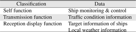
Table 5 listed the functions of the sea MSI fusion and supply system. Display fusion information from devices about position, course, speed etc. Other onboard devices provide information about the locational relationship of ships (using Radar and AIS), and weather information specific to the ship’s location (wind direction and speed, current). Devices used for receiving safety information (through text broadcasting) are also found onboard. These devices transmit information through the AIS and receive information necessary for navigation safety from other ships and from land.
[Table 5.] Functions of seaMSI system
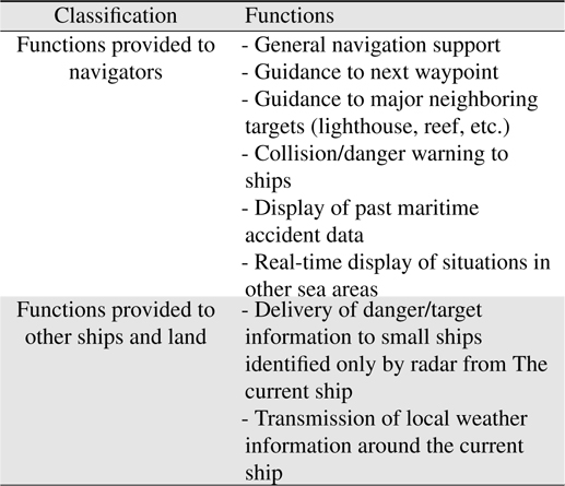
Functions of seaMSI system
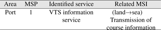
On Saenuri’s test voyage out of Mokpo, transmission and reception tests were conducted between land and sea MSI test terminals. The test conditions, which were the same as the conditions of MSP 1 (VTS information service) at the port area of Mokpo, are listed in Table 6.
[Table 6.] On-the-ship test condition
On-the-ship test condition
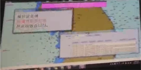
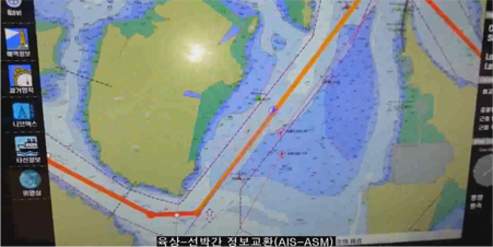
As shown in Figure 10, the target course information was transmitted from the land MSI test terminal to the sea MSI test terminal, and as shown in Figure 11, the display of a normal reception was confirmed.
5. Conclusions and Future Research
IMO has determined that more than 80% of maritime accidents are caused by human error. A variety of methods have been considered to reduce maritime accidents caused by such human error. Various navigational devices have been installed inside the bridges of ships and navigators observe surrounding maritime situations and analyze other information by using these navigational devices. However, because of worker fatigue caused by excessive work aboard high-speed ships, loading and unloading, and excessive paper work for ship operation, safe navigation is now threatened. Therefore technologies that aid navigator decision making have been proposed to reduce the numbers of accidents caused by human factors.
This study proposes a system to safe navigation by assisting navigators through the delivery of MSI between land and sea.
The results of this research are summarized as follows.
A land MSI system was constructed that allows safety information to be received from the sea and processed on land MSI is processed and propagated based on the safety information source database. In addition, a sea MSI system was constructed. This system receives electronic data related to maritime safety from seven inboard navigation devices and transmits this information to concerned parties on land and sea.
In the future, supplementing the system through long-term on-the-ship tests is necessary by defining MSI in relation to the MSP region.