For the first time, a novel analytical model of the net gain for a Raman-EDFA hybrid optical amplifier (HOA) is proposed and its various parameters optimized using a genetic algorithm. Our method has been shown to be robust in the simultaneous analysis of multiple parameters (Raman length, EDFA length, and pump powers) to obtain large gain. The optimized HOA is further investigated at the system level for the scenario of a 50-channel DWDM system with 0.2-nm channel spacing. With an optimized HOA, a flat gain of >17 dB is obtained over the effective ITU-T wavelength grid with a variation of less than 1.5 dB, without using any gain-flattening technique. The obtained noise figure is also the lowest value ever reported for a Raman-EDFA HOA at reduced channel spacing.
The hybrid optical amplifier (HOA), composed of a Raman and an erbium-doped fiber amplifier (EDFA), has emerged as a promising solution for extending the span and transmission capacity of dense wavelength division multiplexed (DWDM) systems [1]. It is attractive because of its ability to tailor the gain profile, compensate for fiber dispersion loss, and suppress spontaneous noise [2]. Although Raman-only amplifiers have demonstrated the capability to improve system BER performance, Raman–EDFA HOAs are comparatively more power-efficient and cost-effective [3, 4]. However, a drawback of a Raman amplifier is that nonlinear effects such as stimulated Brillouin scattering, self-phase modulation, cross-phase modulation, and four-wave mixing degrade the signal when the amplifier has large output power [5]. On the other hand, the nonuniform gain spectrum in conjunction with the saturation effects in EDFAs cause an increase in signal power and decrease the optical signal-to-noise ratio unacceptably [6]. Therefore, both the amplifiers and their applied systems must be carefully designed to install an HOA in a DWDM system at reduced channel spacing.
Thus it is mandatory to optimize the important parameters (such as Raman length, EDFA length and pump power, etc.) before an HOA is deployed. In the literature, various optimization techniques are used to optimize the parameters of HOAs to improve system performance in the terms of gain, gain flatness, transient effect, etc.
Carena
Recently we have proposed various combinations of optical amplifiers and investigated the impact of reduced channel spacing at high bit rates [12]. It was observed that the Raman-EDFA HOA is the best combination, but in this investigation optimization of HOA was not performed. In this paper we extend the previous results of [8-12] by designing a net-gain mathematical model and optimizing the Raman-EDFA HOA using a genetic algorithm.
This paper is organized as follows. A model for the gain of the Raman-EDFA HOA is described in Section II. In Sections III and IV the proposed genetic algorithm and its analogy for an optical system is presented to provide the optimal parameters. The system setup and results are described in Section IV. Section V summarizes the conclusions.
II. MODEL FOR THE GAIN OF A RAMAN-EDFA HOA
As mentioned, previously the total gain of cascaded amplifiers was considered to be the sum or product of their individual gains, but the gain of the second cascaded amplifier (net gain) depends on the first amplifier's gain. Thus in this section we derive a net-gain model by considering those actual conditions. The mathematical model is divided into two parts: In part A an expression for variation of pump power and signal power along the EDFA length is determined, while in part B, after considering the effect of Raman output power on EDFA power, an expression for the net signal gain is established.
In this investigation, the EDFA is assumed or modeled as two-level system, so

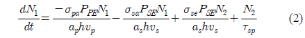
where N1 is the population density in the ground state, N2 is the population density in the meta stable state, and Nt is the total erbium ion density in the core of the EDFA. Then the rate of change of population N1 at ground-level energy E1 is given as [13]:
where PPE is the pump power, PSE is the signal power, σ pa is the absorption cross section at pump frequency 𝜐
On the right-hand side of equation (2), the first term is the rate of absorption per unit volume from E1 to E3 due to pumping, the second term is the rate of absorption per unit volume from E1 to E2 due to the signal, the third term is the rate of stimulated emission per unit volume from E2 to E1 due to the signal, and the fourth term is the rate of spontaneous emission per unit volume from E2 to E1 due to the signal.
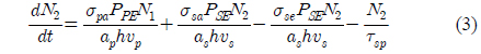
Similarly, the rate of change of population N2 at the upper amplifier level is [13]:
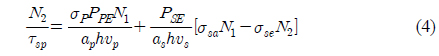
Under the steady-state condition Substituting this expression into (3), after rearrangement the expression becomes:
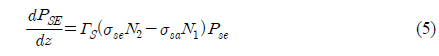
By neglecting the contribution of spontaneous emission, the variations of the pump power Pp and the signal power Ps along the length of amplifier are calculated as:

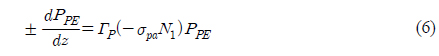
In equations (5) and (6) the fiber losses (𝛼 and 𝛼′) are also neglected for small erbium-fiber length.
2.2. Analytical Computation of Net Gain
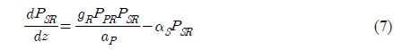
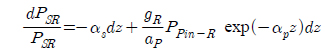
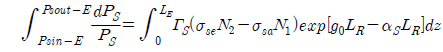
To determine the net gain, first we have to calculate the Raman output power, and then final gain is calculated by substituting this power into equations (5) and (6). The Raman-amplification process is governed by the following set of two coupled equations by considering a single continuous wave pump beam to amplify an optical signal [14].

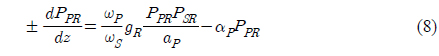
where PSR is the signal power for the Raman amplifier, gR is the Raman gain coefficient, PPR is the pump power for the Raman amplifier, ap is the cross-sectional area of the pump beam inside the fiber, 𝛼
For practical situations, the pump power is so large compared to signal power that pump depletion can be neglected by setting gR=0 in equation (8) and considering forward pumping only [15],
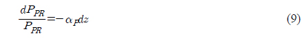
Integrating both sides,

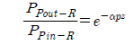
After solving we have:

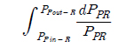
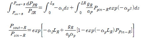
From this equation the Raman output power can be calculated as:

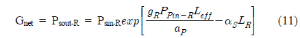
Substituting the value of PPR = PPout-R in equation (7),

Integrating both sides,
Now the net gain (Gnet) can be calculated as:

where
Now dividing and multiplying the second term of equation (11) by LR:
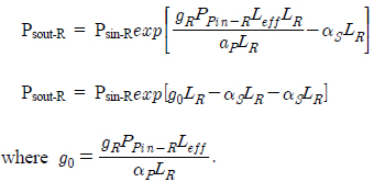
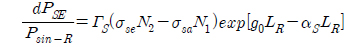
Also, Psout-R = PSE is the input signal to the EDFA.
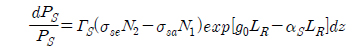
Substituting the value of PSE into (5) and rearranging:

For convenience in solving this equation, let us denote signal power by Ps only,

Integrating both sides for LE as the length of the EDFA,

From equation (1) we see that N1=Nt−N2.
Using the expression for N1 in the above equation we get:

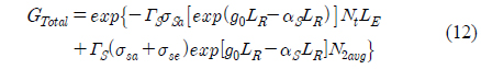
After a long calculation and taking the exponential of both sides we have:

where pump rate 𝜔
III. MULTIPARAMETER OPTIMIZATION USING A GENETIC ALGORITHM (GA)
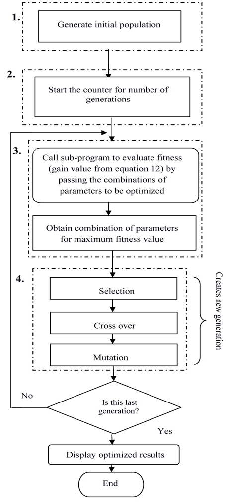
This section starts with an overview of the GA, followed by its implementation for optimization of a Raman-EDFA HOA. A GA is a global search optimization algorithm based on biological evolution. A GA allows a population composed of many individuals to evolve to a state that maximizes “fitness” under specified selection rules. The details and implementation of GA can be found in [10].
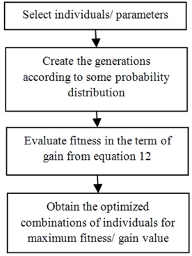
Applying this simple GA in the optimization of an HOA can be broadly subdivided into the following steps, and their sequence can be represented by the flow diagram of Fig. 1.
Step 1: Initialization of GA parameters and population for the various system parameters, i.e. Raman length, EDFA length, and pump powers. During this stage the ranges for the parameters, i.e. the limits of the search space, are defined. The parameters for the GA and ranges of values for the HOA are given in Tables 1 and 2 respectively.
[TABLE 1.] Parameters for the GA
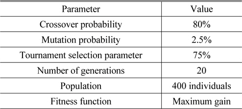
Parameters for the GA
[TABLE 2.] Range of values for HOA parameters
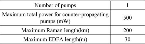
Range of values for HOA parameters
Step 2: The counter is started for the number of generations at the beginning. The generations proceed iteratively towards the desired results.
Step 3: For each generation there are substages to evaluate the fitness value (i.e. gain) and then modify the set of parameters to achieve maximum gain. Evaluation of amplifier gain for the various combinations of parameters is performed by calling the HOA model as a subprogram. The set of parameters obtained from a randomly generated population is passed within the function call to the subprogram one by one, for the whole population. This subprogram, upon receiving the combination of all parameters to be optimized, repeatedly evaluates the gain using equation (12) and returns the average value. The current fitness value is compared to the previous fitness, and if it is greater then its set of parameters is taken as the better solution
Step 4: During the next substage the current population of individuals is modified. The fitness value and selection probability are passed to the selection function. Here the fitness is an array of gain values respective to the set of all parameters in the current population. Tournament selection chooses a random value for chromosomes depending on a small probability, as defined in Table 1. New chromosome pairs are obtained from these selected chromosomes by a crossover method. These newly generated chromosomes form a temporary new population which replaces the original population after a mutation operation has been performed on each of the new chromosomes. Finally a new, improved population is obtained.
Steps 3 and 4 are repeated until the final generation is reached. It can be seen that the amplifier gain increases with the succession of generations. Since the proposed method for employing the GA includes tournament selection, crossover method, and mutation adopted collectively, it converges on the maximum gain in a few generations, after which further modification is undesirable.
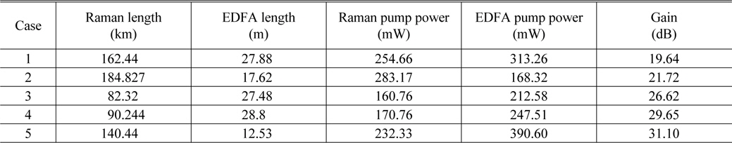
Table 3 shows selected results obtained from the genetic algorithm as a function of the expected gain of more than 30 dB. The maximum gain (31.1 dB) is obtained for the optimal solution presented in Case 5.
[TABLE 3.] Gain obtained from various combinations of parameters (cases)

Gain obtained from various combinations of parameters (cases)
IV. ANALOGY OF THE GENETIC ALGORITHM TO A PROPOSED OPTICAL COMMUNICATION SYSTEM
In this section we describe an analogy of the GA to an optical communication system. In general the GA is a biological evolution method to search among a large number of possibilities for a solution by varying the combinations of individuals. As the proposed optimization technique is inspired by the GA, we have taken the individuals to be combinations of HOA parameters (such as Raman length, EDFA length, Raman pump power, and EDFA pump power). In the current investigation, by using GA selection rules the individuals/amplifier parameters are varied until the maximum gain is achieved. The flow chart in Fig. 2 clearly shows the analogy of the GA in which the following terms (GA terms and optical-system terms) are associated with each other: individuals ↔ HOA parameters, fitness ↔ gain calculated from equation 12, generation ↔ combinations of individuals/amplifier parameters.
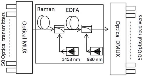
5.1. Simulation of the Optimized HOA for a DWDM System
To check the performance of the optimized HOA at the system level, a numerical simulation is carried out. The system setup consists of 50 DWDM channels, according to the ITU-T G.694.1 standard, with a wavelength spacing of 0.2 nm using continuous-wave lasers, as shown in Fig. 3. We have investigated this system with per-channel input laser powers of -10 dBm. The data stream from a 10 Gbps pattern generator with an NRZ binary sequence is pre-coded and drives a sine-squared amplitude modulator. The optimized parameters of different fibers and pumps are taken from Case 5, as described in Table 3.
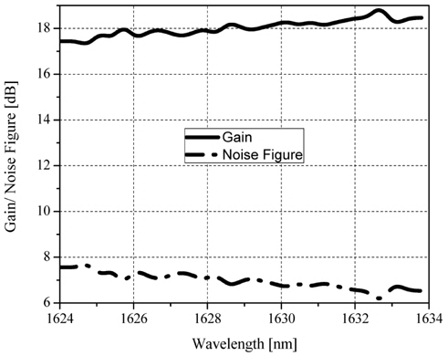
Figure 4 shows the gain and noise spectra for the optimized Raman-EDFA HOA over the ITU-T channels. The variation of gain with wavelength is not uniform, as each amplifier induces its own nonlinearities. It can be observed that each wavelength has a gain of more than 17 dB. In the simulation various losses have been considered, such as attenuation due to fiber and other optical components, coupler losses, etc., unlike in the mathematical analysis represented in Section 2. This is the reason for the reduction of gain in the simulation. Using the optimized parameters we have obtained ̴1.5 dB of gain flatness with less than 7.7 dB of noise per channel, which shows an improvement even at this compact channel spacing [1,5]. This noise figure is observed due to the pumping scheme used (counterpropagating pump) and large Raman fiber length (140.44 km), as also reported in [16].
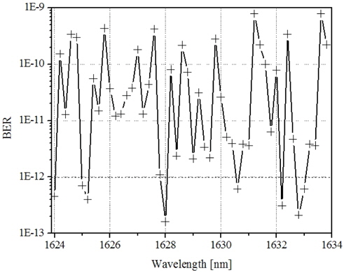
Due to the gain dynamics induced by the optimized HOA, distortion of pulse shapes and crosstalk between channels are present. These crosstalk effects are due to the induced nonlinearities such as stimulated Raman scattering, four-wave mixing, self- and cross-phase modulation, etc. The induced crosstalk directly affects the bit error rate of the system. The BER also varies according to the signal format, dispersion, and transmission speed, as well as noise accumulation, saturation, and reflection effects through the amplifiers.
In our simulation the BER is calculated using the following equation:

where the quality factor Q can be calculated from:
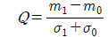
in which m1 and σ1 (m0 and σ0) are respectively the mean and the standard deviation of the received signal at the sampling instant when a logical “1” (“0”) is transmitted.
In Fig. 5 the variation of bit error rate among the DWDM channels is detected due to crosstalk between those channels having the different data symbols. Even so, the proposed system provides an acceptable bit error rate <1×10⁻⁹ [10] over the effective bandwidth.
In this paper we have proposed a new analytical model for the gain of a Raman-EDFA HOA and the final gain equation is used to optimize the multiple parameters using a genetic algorithm. This algorithm has proven to be robust in refining the search for the optimal Raman length, EDFA length, and pump powers required for the best configuration of the proposed HOA. In a simulation using the optimal parameters (Raman length 140.4 km, EDFA length 12.5 m, Raman pump power 232.3 mW, and EDFA pump power 390.6 mW), the proposed Raman-EDFA provides a flat gain >17 dB with a gain variation of less than 1.5 dB.