A novel antenna with ellipsoid-paraboloid surfaces configuration is designed for matching the incident radial radiation fiber laser distribution for maximum transmission efficiency. The on-axial and off-axial defocus effects on the optical antenna system, resulting in energy loss, are analyzed in detail. Knowledge of the effects of those defocuses on beam divergence, aberration and antenna transmission efficiency is of great importance to the long range communication systems.
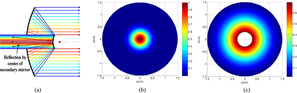
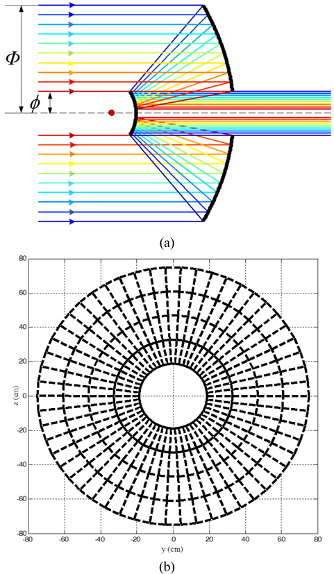
Laser communications and radar systems employ conventional telescopes as optical antennas. These telescopes, such as Cassegrain telescopes, are always illuminated by an on-axial emission semiconductor laser and frequently have reflection caused by the secondary mirror center is shown in Fig. 1(a). Intensity patterns of an input Gaussian laser beam and truncated Gaussian beam emitted from the antenna are given in Fig. 1(b) and (c), respectively. Because of the on-axial transmission, energy loss caused by the secondary mirror center reflection will greatly depress the emission efficiency in the optical communication system [1-3].
In recent years, fiber lasers attract very much attention [4, 5]. They are capable of producing stable,high power, allow design freedom, and produce good coherence radiation. They may prove to be an important new light source for applications in medical imaging, sensing, bio-sensing and optical communication systems[6, 7]. In April 2012, an important development in this area: a radial radiation laser using a hollow-core Bragg fiber in combination with organic dye-doped water plugs placed inside the fiber core, was reported in Nature Photonics[8]. This kind of fiber laser is on-axial pumped, resulting in a unique radiating field pattern characterized by cylindrical symmetry and a fixed polarization pointed in the azimuthal direction[9]. This new capability may prove to be an important new light source for applications in space optical communication systems.
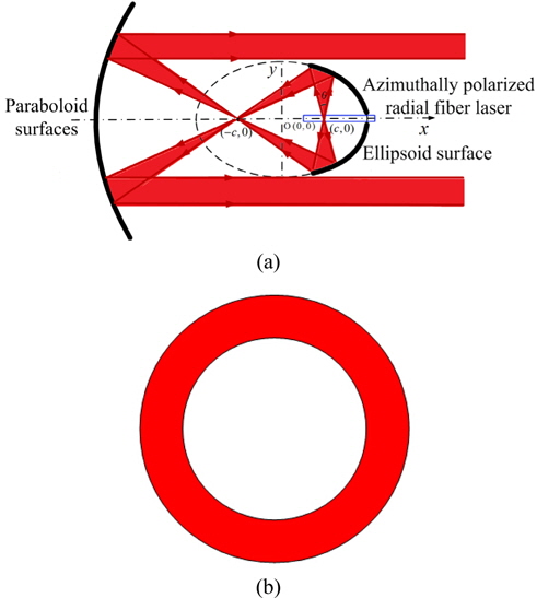
In this paper, a novel optical antenna with ellipsoid-paraboloid mirror surfaces is constructed, which is assumed to be illuminated by a radial radiation fiber laser (as shown in Fig. 2(a)), producing stable, on-axially symmetric ring-like radiation (as shown in Fig. 2(b)).
By geometrical optical theory, the design details are proposed and the resultant curves that display the energy loss of the communication system due to defocus between primary and secondary mirrors of emitting antenna are presented. This new type of antenna illuminated by a radial radiation fiber laser, which produces a hollow beam of high precision collimation, may effectively avoid the energy loss caused by the secondary mirror central reflection in the traditional on-axial propagation optical antenna. The investigation results will offer fundamental research for the collimation accuracy and propagation efficiency enhancement of the free space optical communication.
II. DESIGN OF THE ELLIPSOID-PARABOLOID SURFACES ANTENNA
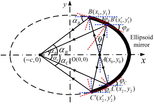
Figure 3 shows the two-dimensional structure model of the ellipsoid mirror surface in the xy plane, which performs as a secondary mirror, and is illuminated by a radial radiation fiber laser. The center of the ellipse is at origin point
The radial emitting region of the fiber laser, which can be regarded as a point course, is located at the right side focus of the ellipse, its coordinate is
where is the slope of the emitting light .
Two sets of solutions , derived by solving Eq. (1), represent two intersections of emitting light and the ellipsoid mirror surface.
By deriving the ellipse equation the slope of the tangent at point
The slope angle of reflecting light at point
The two-dimensional structure of the ellipsoid-paraboloid mirror surfaces is shown in Fig. 4. The equations of reflecting light and the paraboloid mirror, which performs as a primary mirror of the emitting antenna, is shown below

where
The divergence angle of the outer edge reflecting light below the

The divergence angle of the outer edge reflecting light above the

The divergence angles of inner edge reflecting light below and above the
In any case, when
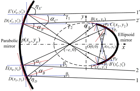
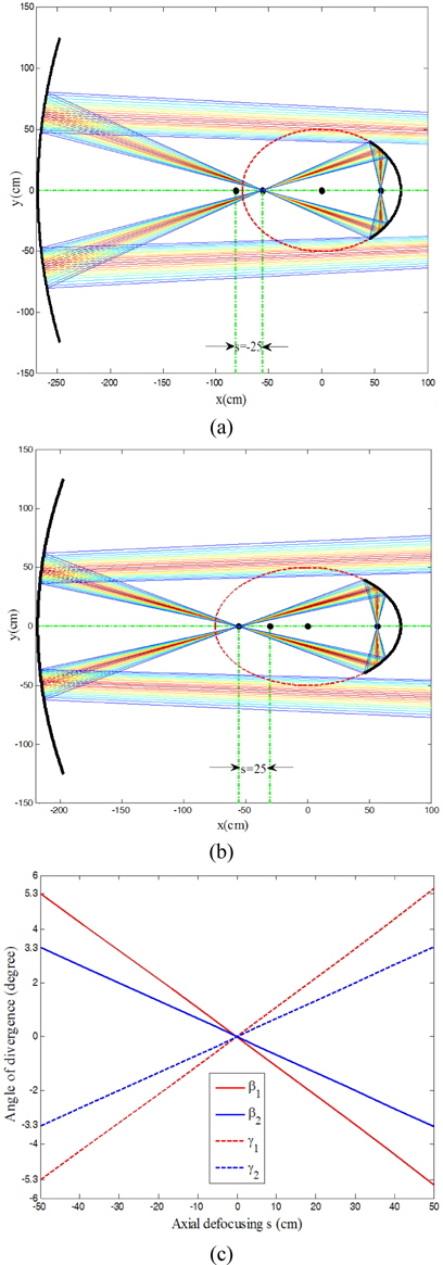
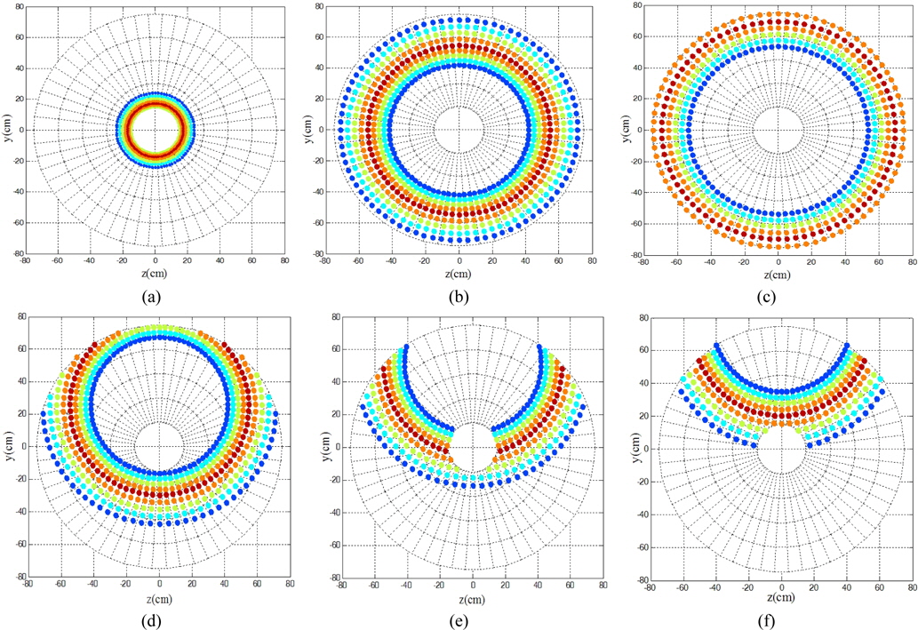
Suppose the focus of the parabola overlaps with the left focus of the ellipse, it means that the coordinate of the parabola apex is . Two-dimensional ray tracing simulation results, and the curves of the divergence angles of the edge emitting light are shown in Fig. 5.
In Fig. 5(a), color of lines from red to blue represent energy changes from high to low level. Fig. 5(b) shows that the divergence angles of inner and outer edge laser beam overlapped each other and all approach to 0 degrees, which means a precision collimated laser beam, which hopefully approaches the diffraction limit, will be produced by the confocal optical emitting antenna. This kind of novel antenna could greatly enhance the emission efficiency and collimation accuracy of optical antenna system for long range optical communication.
3.1. On-axial and Off-axial Defocus Analysis of Ellipsoid- Paraboloid Surfaces
Some mechanical assembly errors could cause the on-axial defocus of the ellipsoid-paraboloid mirror surfaces. And some thermal expansion damages may cause off-axial defocus of the two reflectors [10].
Suppose the amount of on-axial defocusing is
It has been presented in part II that
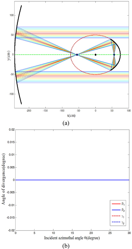
Figure 7(a) and Fig. 7(b) shows two-dimensional ray tracing simulation results of an antenna with two different off-axial defocusing amounts. The emitting light tilts downward when the off-axial defocusing amount is
It can be seen from Fig. 7(c) that when the off-axial defocusing
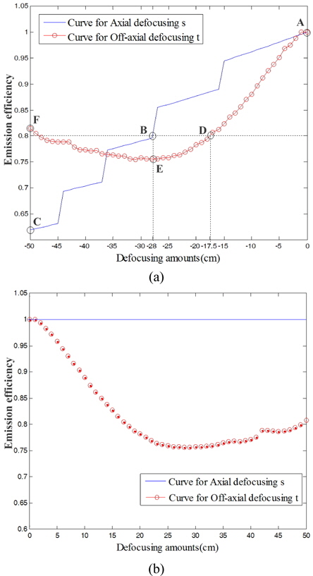
The curve for the on-axial defocusing presented by the solid line in Fig. 8(a), when the on-axial defocusing amount
For the off-axial defocus case, the emitting light tilts downward when the off-axial defocusing amount
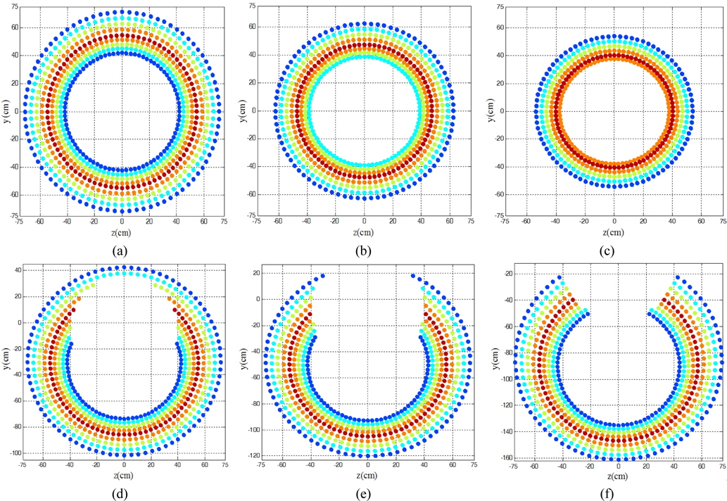
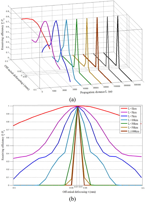
Figure 9 shows spot diagrams with different defocusing amounts, obtained at the plane positioned at
When the confocal condition is satisfied, transmitting light is a high-precision collimated hollow beam, and just in time to avoid the secondary mirror blocking (as shown in Fig. 9(a)). The emission efficiency is 100% (corresponding to point A in Fig. 8(a)). For the case of negative on-axial defocusing amounts, i.e.
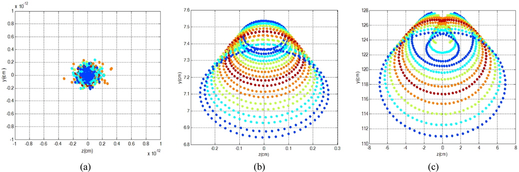
By introducing of an berration-free ideal converging lens at the exit pupil of the emitting antenna, optical aberration can be exactly visible at its image plane. Figure 10 shows spot diagrams obtained at the Gaussian plane of the ideal converging lens.
For the confocal case, spot diameter at the Gaussian plane of the ideal converging lens is approximately 0.4×10⁻¹² (as shown in Fig. 10(a)), the confocal antenna can be regarded as an aberration-free system. Obviously, convergent or divergent output beam caused by on-axial defocusing may shows spherical aberration at the Gaussian plane. For the off-axial defocusing case, small off-axial defocusing amount cause coma aberration (as shown in Fig. 10(b)), too large off-axial defocusing amounts may terminate coma and astigmatism aberrations at same time (as shown in Fig. 10(c)). Thus the smaller the amount of defocusing is, the higher the optical quality of the antenna system is. According to the Strehl criterion, when the receiving efficiency is greater than 80%, the imaging quality of the optical system can be regarded as perfect.
In order to further study the light transmission efficiency in the whole optical communication system, we must not only consider the impact of defocusing amounts and aberrations, but also consider the impact of the transmission distance on the receiving efficiency of the receiving antenna.
IV. SIMULATION RESULTS OF RECEIVING ANTENNA
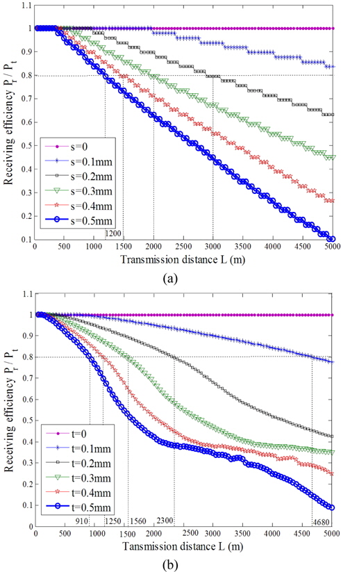
A receiving antenna always uses a typical Cassegrain telescope as shown in Fig. 11(a). The apertures of the primary mirror and secondary mirror are
Figure 12 shows the spot diagrams on the effective receiving plane, which is a distances of 5000 m from the emitting antenna.
In Fig. 12(a), when
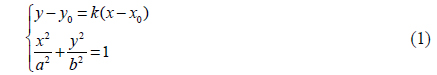
It can be inferred from Fig. 13(a), that when the on-axial defocusing is
It can be also inferred that curves shown in Fig. 13(a) present linear distribution, and curves shown in Fig. 13(b) present nonlinear distribution, which means the effects of off-axial defocusing on the receiving efficiency is greater than that of the on-axial defocusing. Curves of off-axial defocusing
It can be inferred from Fig.14 that for long transmission distance
A novel antenna with ellipsoid-paraboloid surfaces configuration is designed for matching the incident radial radiation fiber laser distribution for maximum transmission efficiency. It can be inferred from simulation results that the effects of off-axial defocusing between the primary and secondary mirrors of emitting antenna on the receiving efficiency is greater than that of the on-axial defocusing. When the absolute value of off-axial defocusing is less than 0.05 mm, curves of receiving efficiency for long transmission distance