The light-emitting diode (LED) achieved recognition as a new lighting device based on its outstanding luminous efficiency, lengthy life, low power consumption and rapid response. LEDs also provide high color efficiency, and do not emit ultraviolet or infrared rays. Since the LED is suitable for manufacturing smallsize lights, it is feasible to develop LED headlamps that can replace traditional halogen bulbs.
Since approximately 60~80% of the LED input power is transformed into heat, the junction temperature of the LED can increase drastically if the thermal management system is poor [1]. If the junction temperature exceeds 150℃, they may become disconnected and completely nonfunctioning. In addition, any temperature increase in the LED may increase the resistance caused by heat, and hinder the flow of electric currents, worsening luminous intensity and chromaticity performance [2,3]. The issue of thermal management poses more serious challenges for lighting equipment that uses high-power LEDs [4-6]. These issues require LED lights to be designed with a variety of thermal management devices, in order to ensure reliable and efficient radiation performance.
In order to address thermal issues, heat pipes were used in a study by Wang et al. [7]. They controlled the ratio of liquidity between 10% and 50%, and demonstrated that heat pipes had the highest efficiency with 30% of liquidity ratio. Li et al. [8] used a loop-type heat pipe, and optimized their shape. In addition, Lin et al. [9] demonstrated the outstanding performance of flat-plate pulsating heat pipes, in comparison with standard pulsating heat pipes. While Ramos-Alvarado et al. [10] showed that it was possible to increase output by combining cold plates and microjets, Faranda et al. [11] showed that forced cooling enhanced cooling performance by over 11.7%, compared to existing natural convection.
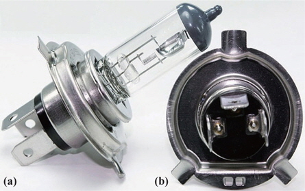
For newly manufactured automobiles, LED headlamps are increasingly being used instead of 55 W halogen lamps, as shown in Fig. 1. In order to replace halogen lamps with LED headlights in used cars, however, it is necessary to exchange the entire headlight module. Since this requires high cost, LED headlights have not been commonly applied to secondhand cars. In order to take advantage of the many merits provided by LED lamps, it is necessary to develop LED headlamps that can replace the halogen bulbs of used cars, and in the process it is most important to obtain outstanding heat radiation performance.
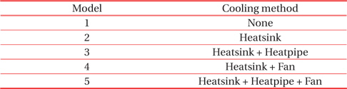
Against this backdrop, this paper aimed to develop an LED headlamp that would be able to replace a halogen bulb at or below the junction temperature of 90℃ by combining a high-power LED, heat sink, heat pipe and fan. To this end, a headlamp apparatus and thermal management device were each designed, and a prototype was made to verify the performance. Table 1 shows the heat radiation device installed on the model considered in this paper.
[Table 1.] Summary of Numerical models.

Summary of Numerical models.
Ansys Fluent [12], a commercial program designed to interpret computational fluids, was used to study the conduction, radiation, and convection in the model LED headlamps being developed to replace halogen bulbs. Another commercial program, Catia [13] was used for the purposes of three-dimensional modeling.
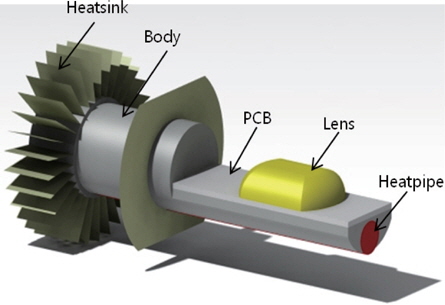
Figure 2 illustrates a numerical model to efficiently analyze the LED headlamps to be used as a substitute for halogen bulbs. An LED headlamp model consists of an LED, printed circuit board (PCB), body, heat sink and heat pipe. The LED module is cooled by flows within the headlamp that are generated by natural convection produced by the heat sink and body, and by forced convection by the fan.
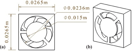
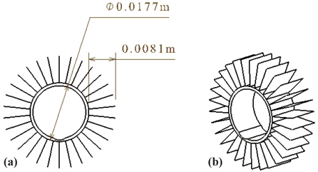
The turbulent flows of the LED headlamps were interpreted with the k-ε model, and their radiation with the discrete ordinates (DO) model. In the case of cooling through natural convection, the effect of radiation is particularly important. The fan for forced-convection cooling was modeled using the multiple rotating frame (MRF) method. The specifications of the fan are provided in Fig. 3. The diameter of the hub is 0.015 m, and the fan has five blades in total. The revolution of the fan is 13,000 rpm, according to the manufacturer’s datasheet. This paper also assumed the heating value of the LED to be 80% of the input power of 20 W, based on the manufacturer’s datasheet [14]. The heat pipe is 0.07 m long and 0.006 m in diameter, and the working fluid is HCFC-123. Contact thermal resistance of the LED chip and soldering point was set as 2.2 W/K, after referring to the specification provided by the manufacturer [14]. Figure 4 is a schematic diagram of the heat sink, which has a total of 30 fins, each with a heating surface area of 0.000162 m2.
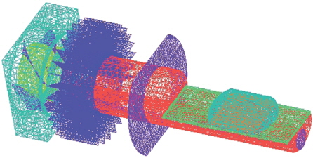
Figure 5 provides a mesh model to perform the numerical analysis; ICEM-CFD [15], a commercial program, was used for approximately 680,000 meshes.
3.1 Changes in temperature distribution of each model
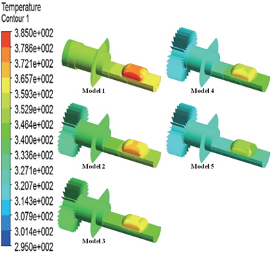
Figure 6 shows the temperature level contours of LED headlamps with different types of coolers. With the LED module attached to an aluminum body, Model 1 has poor heat radiation, indicating that heat is concentrated around the LED. In order to increase the heating surface area, a heat sink was added to Model 2. As a result, the heat around the LED was more dispersed, but the effect was not considerable. This meant that, despite the installment of the heat sink, the heat transfer from the LED was not efficient.
To effectively enhance the heat transfer, a heat pipe was used between the LED and heat sink in Model 3, thereby reducing the thermal resistance between the two parts from 1.07 K/W to 0.29 K/W. Based on the enhanced heat transfer from the LED to heat sink in Model 3, the temperature fell in the LED and lens, and increased in the heat sink. Due to the considerably high thermal resistance from the heat sink to the air, however, it became necessary to ensure cooling through forced convection, instead of natural convection.
To further improve the cooling performance, a cooling fan was installed on Model 4, without the heat pipe. Compared to Model 3, the temperature of the heat sink of Model 4 was observed to fall considerably, as a result of the effect of the cooling fan. The temperature level contour of the LED and lens remained similar, however, suggesting that the heat of the LED was not efficiently transferred to the heat sink. Consequently, Model 5 was equipped with all three components, the heat sink, heat pipe and fan. In the final case, the heat pipe helped to transfer the heat efficiently from the LED to the heat sink, and the cooling fan reduced the thermal resistance between the heat sink and the air, resulting in highly efficient cooling performance.
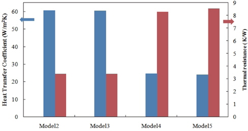
Figure 7 provides the values of heat transfer coefficients and thermal resistance, which help to explain the level of thermal resistance between the heat sink and the ambient air. Heat transfer coefficients were obtained from the interpretation of conjugate heat transfer by Fluent. The thermal resistance was 1/(hA), and in inverse proportion to the heat transfer area of the heat sink (A) and heat transfer coefficient (h). In Models 2 and 3 with a natural convection cooling system, the average heat transfer coefficient of the heat sink was approximately 24 W/m2K, while the value was around 60 W/m2K in Models 4 and 5, which employed a forced convection cooling system. This corresponds to an increased cooling rate of about 250%, and had the effect of reducing the actual thermal resistance from 8.53 K/W to 3.41 K/ W.
3.2 Junction temperature by model type
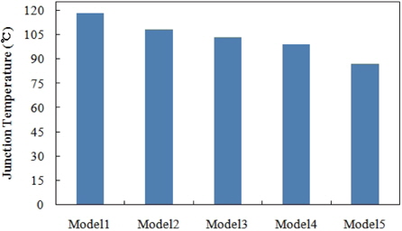
Since LED headlamps with lower junction temperature feature higher efficiency and longer life, this paper set the target junction temperature as 90℃. Figure 8 provides the changes in junction temperature of each model. The junction temperature of Model 1 is about 119℃, which is too high compared to the target temperature. However, Model 2 with the heat sink showed a slightly improved heat radiation performance, around 10℃ lower compared to Model 1. It was still true, however, that the heat sink would not be enough to obtain the desired cooling performance. By adding a heat pipe to further improve the radiation performance, as in Model 3, the temperature was lowered by an additional 5℃. In order to reduce the temperature further, it was necessary to employ forced convection, using a fan. Model 4 was made by installing a fan to Model 2, with its junction temperature standing at 99℃, but it still failed to reach the targeted cooling performance. Finally, a heat pipe was installed to Model 4, and this Model 5 attained the target performance with its junction temperature at 87℃. This became possible by optimizing the thermal resistance between the LED and heat sink, and between the heat sink and ambient air.
3.3 Production of prototype and measurement of junction temperature
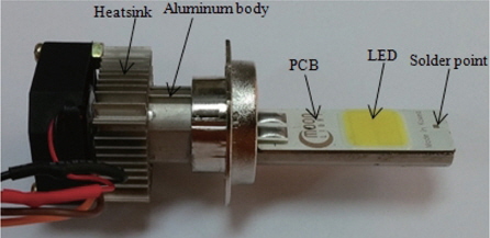
Figure 9 shows the variation of the junction temperature for different models. The PCB and the body as well as the body and heat sink were soldered to minimize contact thermal resistance. The headlight body and heat sink were made of aluminum, and the fan spun at approximately 13,000 rpm. The LED had a forward voltage of 13.7 V and forward current of 1.45 A, and the input-output of the headlamp, Pinput, was about 19.8 W. The temperature was measured using a T-type thermocouple to the soldering point of the PCB.
When power was supplied, the temperature became stable after 40 minutes, and the soldering point temperature was then measured to be 42℃. Using this soldering-point temperature and the value of thermal resistance provided by the manufacturer, the value of the junction temperature was obtained by the following formula:

Since the thermal resistance (Θj-sp) was 2.2 K/W, the junction temperature was calculated to be about 86℃. Therefore, it is experimentally proved that the junction temperature of the LED headlamp developed in this paper is below 90℃, the target temperature.
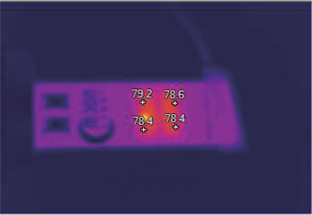
Figure 10 indicates the overall temperature distribution of the LED headlamp measured by IR camera. The lens surrounding the LED chip is a silicon-type, and its emissivity is presumed to be 0.9. The actual LED module consists of 12 chips (four rows and three columns), and the temperature is slightly different at differently located chips. The IR camera measured temperature at four spots on the lens, and the results show that the average temperature of the lens is 78.6℃, and the variation is approximately 0.8℃. This indicates that the value of thermal resistance from the LED chip to the lens is about 0.4 K/W.
Lastly, the LED headlamp was actually attached to a car, and its intensity of illumination was compared to that of an existing halogen headlamp. Measured about 0.5 m distance from the headlamp, the existing halogen lamp was 17,100 lx, while the LED headlamp was 18,500 lx, showing that the LED headlamp features better performance, in terms of intensity of illumination.
This paper developed a new LED headlamp with high efficiency and long life to replace the halogen bulb in used cars. To qualify as an efficient alternative to the halogen bulb, the new LED headlamp had to ensure outstanding thermal management performance within the actual spatial restrictions. A number of cooling devices were optimized based on the CFD interpretation, and the models were verified by prototype. The results show that:
(1)The biggest obstacles to the efficient cooling of the LED headlamp are, among others, thermal resistance between the heat sink and the ambient air, and from the LED module to the heat sink. The research results suggest that using forced convection with a fan and increasing thermal conduction through a heat pipe is the most efficient way to reduce such thermal resistance.
(2) The numerical paper shows that the junction temperature only decreases by 10℃ with the use of the heatsink, and by 15℃ when a heat pipe is added. The temperature falls by 19℃ when a fan is additionally used along with the heat sink, and the combination of the heat sink, heat pipe, and cooling fan further lowers the junction temperature of the LED to 87℃, going below the target temperature of 90℃.
(3) The junction temperature of the prototype was measured to be 86℃, lower than the target junction temperature. This means the successful development of an LED headlamp with high efficiency and long life that can replace the traditional halogen bulbs.
(4) Measured at 0.5 m distance from the headlamp, the intensity of illumination of the existing halogen bulb and the newly developed LED headlamp were approximately 17,000 lx and 18,000 lx, respectively, indicating that the LED headlamp had fairly higher performance.
This paper supports the expectation that it would be possible to further improve the LED headlamp by enhancing the performances of the heat sink and the fan.