The first Korean satellite laser ranging (SLR) system, Daedeok SLR station (DAEK station) was developed by Korea Astronomy and Space Science Institute (KASI) in 2012, whose main objectives are space geodesy researches. In consequence, Korea became the 25th country that operates SLR system supplementing the international laser tracking network. The DAEK station is designed to be capable of 2 kHz laser ranging with precision of a few mm both in daytime and nighttime observation of satellites with laser retro-reflector array (LRA) up to the altitude of 25,000 km. In this study, characteristics and specifications of DAEK station are investigated and its data quality is evaluated and compared with International Laser Ranging Service (ILRS) stations in terms of single-shot ranging precision. The analysis results demonstrated that the DAEK station shows good ranging performance to a few mm precision. Currently, the DAEK station is under normal operations at KASI headquarters, however, it will be moved to Sejong city in 2014 to function as a fundamental station for space geodesy researches in combination with other space geodesy systems (GNSS, VLBI, DORIS, etc.).
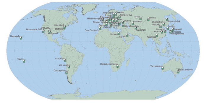
Satellite laser ranging (SLR) is considered to be the most accurate technique currently available for the precise orbit determination of Earth satellites. The SLR observation is a two-way time-of-flight (TOF) measurement of a short laser pulse reflected by retro-reflector targets onboard an artificial satellite. The returning photons are detected at the SLR station with single-shot precision of a few picoseconds, equivalent to one-way range precision of a millimeter (Degnan 1994). The data are collected, archived and distributed by the International Laser Ranging Service (http://ilrs.gsfc.nasa.gov) and are made public in an instant through two data centers (Crustal Dynamics Data Information System (CDDIS) and EUROLAS Data Center (EDC)) in the form of so-called normal points. Normal points are formed by averaging single-shot range measurements (full-rate data) over time-intervals that vary according to the height of the given satellite; in this way the random noise of a normal point is reduced compared to that of an individual measurement, without loss of information from the orbital dynamics. In addition to this primary science product, some stations choose to submit their full-rate data which are records of every successful SLR observation of a satellite. And those have been used for space geodesy, geophysics, lunar and planetary exploration (Degnan 1993), and scientific experiments such as the verification of relativity theory. There are about 50 SLR stations worldwide and more than 30 stations among them are currently under normal operations as shown Fig. 1 (http://ilrs.gsfc.nasa.gov/network/stations/index.html). Over the past ten years, several SLR stations, such as Graz and Shanghai, have upgraded their system to be capable of laser ranging for uncooperative targets without LRA such as space debris (Zhang et al. 2012, Georg et al. 2013).
In recent SLR technologies, there are four trends to reduce operation costs and increase the quantity of measurement data: high level of automation, kilohertz laser ranging, eye-safe operation, and millimeter accuracy. In particular, many SLR stations have tried to upgrade to the kilohertz system using an ultra-shot laser pulse or a fully automated system. The kilohertz system has been used by Graz station since 2003 for the first time to increase the quantity of measurement data and it is now in use by several stations: Graz (Austria), NGSLR (US), Herstmonceux (England), and some stations in China.
Korea Astronomy and Space Science Institute (KASI) has developed its first SLR system called DAEK station which operates at the KASI headquarters with the station code of DAEK obtained from the ILRS in 2012. Thus, Korea became the 25th country that operates SLR systems supplementing the international laser tracking network. The DAEK station provides the high accuracy ranging data that are essential for the development and improvement of the International Terrestrial Reference Frame (ITRF), precision orbit determination, and other space geodesy data products that are essential to the understanding of global change; monitoring of the sea level and glacier and the atmospheric pollutions using the atmospheric correction for SLR. The DAEK station will be moved to Sejong city in 2014 to function as a fundamental station for space geodesy researches (Beutler et al. 2005).
The DAEK station is designed to enable 2 kHz laser ranging in both daytime and nighttime tracking of satellites at an altitude between 300 km and 25,000 km. It has a bistatic optical path employing 40 cm receiving and 10 cm transmitting telescopes. For a daylight tracking and 2 kHz laser ranging, the DAEK station has an event timer, special and narrow band-pass filters, and a high energy laser with 2.5mJ energy per pulse at 2 kHz.
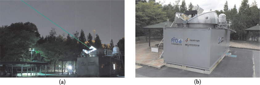
In this study, the technical aspects including characteristics and specifications are addressed for the DAEK station. The ranging precision is also analyzed based on the singleshot root mean square (RMS) of ground calibration of the Starlette and the LAGEOS satellite in order to investigate the system performance compared to the ILRS SLR system. Fig. 2 (a) shows the appearance of DAEK station located at the headquarters of KASI and Fig. 2 (b) shows firing of the laser from the DAEK station.
2. DESCRIPTION OF DAEK STATION SYSTEM
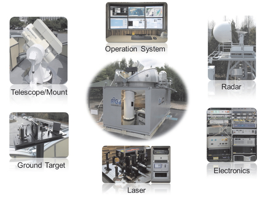
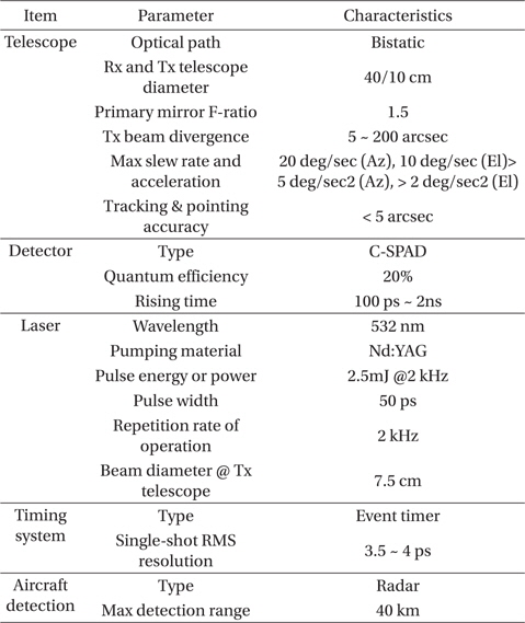
The DAEK station consists of six sub-systems: optical system, optoelectronic system, laser system, tracking mount, operation system, and dome. In addition, it has a laser hazard radar to monitor airplanes, ground targets to calculate the system delay, and weather sensors to correct the atmospheric delay and the refraction based on Marini-Murray model (Marini 1972). Fig. 3 shows the configuration of DAEK station and Table 1 lists its major specifications.
[Table 1] Major specifications of the DAEK station.

Major specifications of the DAEK station.
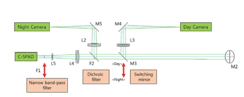
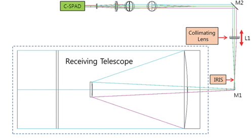
The optical system transmits ultra-short laser pulses to a satellite equipped with a laser retro-reflector array (LRA) and receives the returned signals from the satellite. It is composed of two telescopes and two optical parts: the transmitting and receiving telescope, and the transmitting and detecting optics. The laser beam size is expanded 15 times by two beam expanders in the transmitting optics and 3 times in the transmitting telescope. The beam divergence is adjusted in the range of 5 to 200 arcsec by changing the position of concave in the transmitting telescope, which depends on the satellite altitude. The receiving telescope is a Ritchy-Chretien optical system where the primary and secondary mirrors are hyperboloids. The system F number (the ratio of aperture to focal length) is 10.3 and the primary mirror has the F number of 1.5 (Nah et al. 2013). As shown in Fig. 4 and Fig. 5, there are many optical components in the detecting optics: iris or spatial filters, collimating lens, compensated single photon avalanche diodes (C-SPAD), daytime and nighttime cameras, narrow band-pass filters, and dichroic filters. The iris has three kinds of field of view (30" , 150" , and 300" ) and one blocked spatial filter used for sun screen to protect the C-SPAD against direct sun light; 30" for daytime observations, 150" for dawn and twilight observations, and 300" for nighttime observations, respectively. After passing through the first focus, the beam is collimated by the collimating lens L1 which is used for the focusing of daytime and nighttime cameras and the C-SPAD by moving the collimating lens, L1.
The switching mirror (M3 in Fig. 5) changes the optical beam path for the daytime camera, the C-SPAD, and the nighttime camera showing more than 92 % of reflectivity. The nighttime and daytime cameras are used to detect the transmitted laser beam backscattered from the atmosphere. In a daytime observation, it is very difficult to detect the transmitted laser beam because the background noise is higher than that of a nighttime observation. Hence, the daytime camera is triggered by a start laser pulse with an exposure time of 50 microseconds and then integrates multiple exposure times to get one integrated image frame. In a nighttime observation, the switching mirror is positioned outside the optical beam path for both laser ranging using the C-SPAD and imaging of scattered laser beam using the nighttime camera simultaneously because of the 90% transmittance of the dichroic filter at 532 nm wavelength. The C-SPAD used is manufactured by Peso Consulting in Austria, and PCO 1600 and Watec WAT-120N models are also used for daytime and nighttime cameras, respectively. The detailed specifications of C-SPAD are given by Lim et al. (2011).
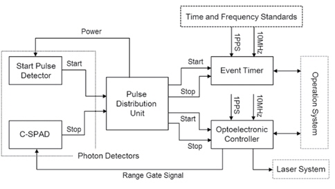
As shown in Fig. 6, the optoelectronic system consists of five components: event timer, time and frequency standards, optoelectronic controller, pulse distribution unit (PDU), and start/stop photon detector. The start photon detector (SPD) uses a photodiodes to detect the leakage of laser pulses through the reflecting mirror in the transmitting optics and then transmits electrical analog signals to the PDU. And the stop photon detector, C-SPAD in the detecting optics also detects returned photons from the satellite or the ground target, and then transmits nuclear instrumentation module (NIM) signals to the PDU. The PDU converts both start and stop signals into transistor-transistor logic (TTL) signals and then transmits them to the event timer which computes the epochs of start and stop signals accurately based on 1 pulse per second (PPS) sync pulses and a 10 MHz reference frequency from the time and frequency standards. In general, SLR system uses two kinds of timing systems to calculate TOF: the interval counter and the event timer. The interval counter measures the elapsed time between emitted and returned laser pulses. Unlike the interval counter, the event timer computes TOF by differencing the emitted laser epoch and the satellite echo epoch. The main objective of SLR system is to determine the distance between the reference point or invariant point of telescope and the center of mass of satellite. The reference point is defined as the intersection between the azimuth axis and elevation axis of telescope rotation.
The TOF measured from the interval counter or the event timer is different from what is expected for the two-way distance between the invariant point and the satellite because it includes system delay caused by cables, electronics, and optical path. The system delay can be obtained from ground calibration by pre-and/or postpass ground target ranging. For the single-shot precision of ground calibration, LAGEOS and Starlette satellites have been considered as an evaluation standard of SLR system performance as well as the precision of normal points of LAGEOS satellite which is generated by International Laser Ranging Service (ILRS) analysis centers (http://ilrs.gsfc. nasa.gov/data_and_products/data/).
In the satellite ranging, the optoelectronic controller generates the laser fire command and the range gate (RG) for C-SPAD activity based on the predicted TOF and start signals from the PDU, which is implemented by field programming gate array (FPGA) board for a fast functional operation. But in the case of ground calibration, it generates the laser fire command and the RG directly without any information of TOF and start signals because the stop pulse arrives at the C-SPAD preceding the RG signals due to the short distance of the ground target. The DAEK station uses A033-ET model as an event timer which records the epochs of start and stop signals and then puts them into buffer for the implementation of kHz laser ranging. But A033-ET is the same as A032-ET in architecture and operation process (Lim et al. 2011).
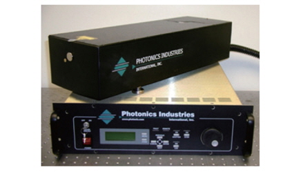
The laser system for the DAEK station is required to be compact in size and should provide kHz repetition rates as well as high energy per pulse in order to increase link budgets (Lim et al. 2011). The DAEK station needs an ultra-short pulsed laser with dozens of pulse widths for better ranging accuracy. As shown in Fig. 7, the RGL-532 model of Photonics Industries (USA) is used for the laser system, which is an Nd:YAG pulse laser: 532nm, 2.5 mJ/pulse, 50 ns pulse width, 2 kHz repetition rate, 0.56 mrad far-filed divergence in full angle, < 5 μrad pointing stability in full angle, 1.26 M2. The beam diameter is 1.9 mm at the exit of the laser head, which is expanded to 28.5 mm by two beam expanders on the optical table.
The tracking mount of DAEK station is altitude-azimuth type, which requires pointing and tracking accuracy less than 5 arcsec. It is designed to meet these accuracy requirements considering telescope and total weight, slew rate, acceleration, and external disturbance from gravity and winds. Hence, main components such as motors, encoders, and bearings were selected according to the required technical specifications: direct drive motors with continuous torque of 344 Nm for azimuth and 138 Nm for elevation, encoders with resolution up to 0.005 arcsec, bearings with P2 precision class. The analysis of static stress due to Earth gravity leads to 17.3 MPa with safety factor of 14. The natural frequencies show 21.5 Hz and 24 Hz for the first and second mode of vibration, respectively. The maximum wind load is 20.4 MPa with a safety factor of 12 at the wind speed of 20 m/s (Park et al. 2012).
The operation system monitors the status of five subsystems and equipment: optical system, optoelectronic system, laser system, tracking mount, dome, laser hazard radar, and weather sensors. In addition, it controls the environmental factors and sub-systems for observation, and generates the final observation products such as raw data and normal point data through polynomial fitting. The operation system was designed to perform many tasks: prediction of satellite ephemeris, computation of RG, generation of position commands for telescope and laser hazard radar pointing, reading epoch data from the event timer, and combination between start epochs and stop epochs. The system has three kinds of operation mode: star calibration, ground calibration, and satellite ranging. The mount model or pointing model is used to calibrate the alignment errors of tracking mount through star calibration. The mount model which is in use at the DAEK station is a classic model with 7 unknown parameters. These parameters are estimated by star calibration considering atmospheric refraction from Marini-Murray model (Marini 1972). The ground calibration is performed by the laser ranging of a ground target to compensate for system delays such as cable and the hardware processing delays. In the satellite ranging mode, RG value, time, and range bias can be also adjusted to increase the returned signal rate.
3. LASER RANGING RESULTS AND ANALYSIS
In general, SLR data quality is evaluated based on six performance parameters: the average single-shot ranging precision of 1)ground calibration, 2)Starlette, and 3)LAGEOS satellite, 4)also the average Normal Point (NP) ranging precision of LAGEOS satellite, and 5)short term and 6)long term bias stability. The first three parameters were obtained from the NP generation process during the last quarter of 2013. The last three parameters are based on rapid orbital analysis results from various SLR data Analysis Centers (ACs). The short term stability is computed as the standard deviation of the pass-by-pass range biases, and the long term stability is the standard deviation of the monthly range bias estimates.
In this study, three kinds of average single-shot ranging precision were used to evaluate DAEK station measurement data quality because other performance parameters were computed by five ACs and will be available on ILRS website after the first quarter of 2014. To compare data quality of the DAEK station with ILRS stations, measurement data set was obtained during the period from 1st Oct. 2013 to 31st Dec. 2013 for the DAEK station and the third quarter of 2013 for the ILRS stations, respectively.
The DAEK station has used only one ground target with a short distance of about 100 cm from the virtual reference point of telescope for ground calibration. The ground target was installed inside the dome, which consists of prism, diffuser, and neutral density filter to decrease laser power to the C-SPAD. The density filter was selected so that the return rate is about 30% without any spatial filter in the nighttime observation. In the case of DAEK station, ground calibration was fulfilled before and after the satellite tracking.
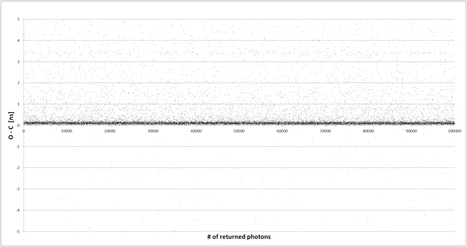
Fig. 8 shows the difference between observation and calculation range values of returned photons in ground target ranging. The calibration correction depends not only on the distance between the virtual reference point and a ground target, but also on the atmospheric conditions such as temperature, pressure, and humidity. In the process of sigma filtering for the elimination of noise signal, the sigma value of 2.2 (scale factor) was used to compute calibration correction because the DAEK station is 2 kHz laser ranging system using the C-SPAD detector.
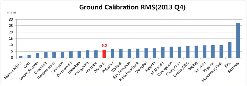
As shown in Fig. 9, the average single-shot ranging precision in the ground target ranging is 6.0 mm for the DAEK station compared to the mean value of 7.6 mm for 26 ILRS stations estimated from the global report cards issued quarterly by the ILRS Central Bureau.
These results depend on the specification of the SLR system, environmental condition (variation of temperature, humidity, etc.), stability of virtual reference point, signal delay by cable, and data analysis techniques in each SLR station.
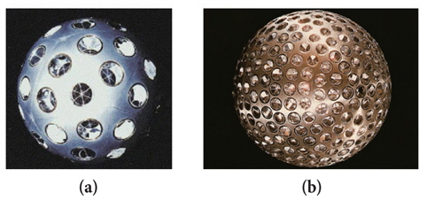
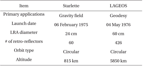
There are many satellites equipped with LRA for geodesy, remote sensing, navigation, and scientific experiments. As shown in Fig. 10, Starlette and LAGEOS satellites have spherical shape covered with retro-reflectors for geodesy research. The specifications of these satellites are shown in Table 2.
[Table 2] Specifications of Starlette and LAGEOS satellites.

Specifications of Starlette and LAGEOS satellites.
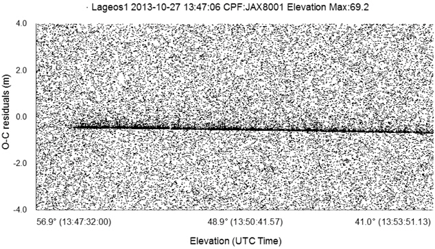
SLR data quality depends on the retro-reflectors characteristics and the accuracy to which the satellite center of mass is measured or modeled as well as SLR system performance. In the process of sigma filtering to generate NP data, sigma value is same as ground target ranging. Fig. 11 shows the RMS values of returned photons from LAGEOS satellite. The solid line in the center is real returned signals from LAGEOS satellite and the others are noise signals.
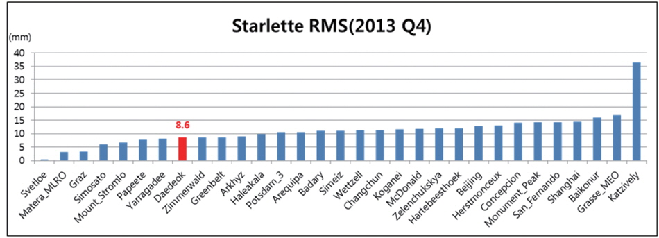
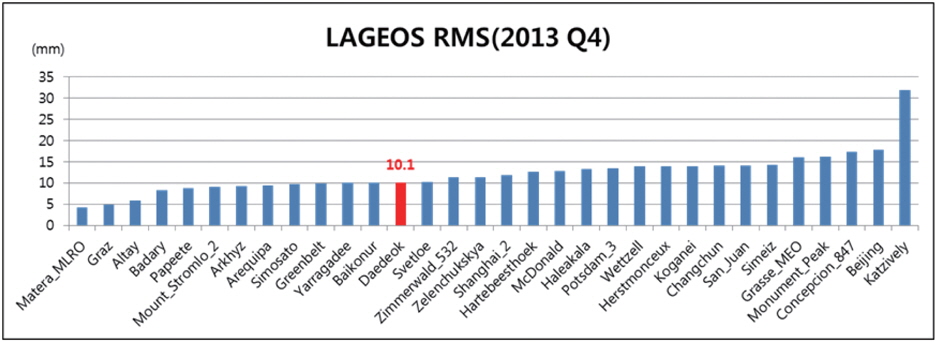
In the Starlette satellite ranging, the average single-shot ranging precision turned out to be 8.6 mm for the DAEK station while the mean value of 31 ILRS stations is 10.9 mm (Fig. 12). In the case of LAGEOS satellite, the DAEK station showed 10.1 mm of ranging precision and 31 ILRS stations showed 12.3 mm as mean. These average single-shot ranging precisions are also given in global report cards (Fig. 13).
These results depend on the specification of the SLR system, observing techniques of satellites, environmental conditions, skills for resolving the system biases (time, range), the tracking accuracy of tracking mount system, and data analysis techniques in each SLR station.
KASI has developed the first Korean SLR system called DAEK station which is designed to enable 2 kHz laser ranging with mm level precision for satellites with LRA from 300 km to 25,000 km altitude. In this study, technical analysis including specifications was described for DAEK station sub-systems, and its data quality was evaluated and compared with that of ILRS stations based on three kinds of average single-shot ranging precision. The ranging performance was compared using measurement data obtained during the period from 1st Oct. 2013 to 31st Dec. 2013 for the DAEK station and during the third quarter of 2013 for ILRS stations, respectively. The results indicate that the DAEK station shows good performance in terms of single-shot ranging precision: 6.0 mm for the ground calibration, 8.6 mm for the Starlette satellite ranging, and 10.1 mm for the LAGEOS satellite ranging. Thus, the DAEK station ranging performance has been demonstrated to a level of a few mm precision, which is better than the mean value of ILRS stations.
The DAEK station will be upgraded into 10 kHz laser ranging in 2014 with a more compact operation system and a new optoelectronic controller which would lead more returned signals and then improve the ranging precision, With the incorporation of these high technologies, it is expected that the DAEK station will play an important role in the development of laser ranging data products.


![The difference between observation and calculation range values of returned photons in ground target ranging. Because we know the exact distance from the start laser pulse to the Ground target, the values of the O-C[ns] should be equal to zero. However, there are non-zero values because of the system delay.](http://oak.go.kr/repository/journal/14366/OJOOBS_2014_v31n3_225_f008.jpg)