If a ship has floodwater and/or liquid cargo inside, the liquid influences the ship motions. The mechanism of this influence depends on the existence of free surface in the tank containing the liquid. If the free surface exists, the motion of liquid is relatively free compared with when no free surface exists. In statics with free surface, the center of gravity can move and change the restoring force, which is called the free surface effect. However, when a ship motion problem is considered in a typical ocean environment, the motion of the ship induces the motion of the liquid in a tank, and at the same time the motion of the liquid in the tank also imparts the hydrodynamic excitations to the motion of the ship. This is fully coupled problem. When we further assume the tank to be completely filled, i.e., no free surface in the tank, the effect of the liquid in the tank can be treated as a solid for the recti-linear motions of the ship: this particular case reduces to be trivial since there is no liquid motion in the tank with respect to the ship motions. However, when a ship undergoes angular motions, then the liquid in the tank can no longer to be treated as a solid for the computation of the moment of inertia of that.
It is well known that the study of the liquid in a ship was started by W. Froude in 1874 as he conducted the model test to see the effectiveness of free surface tank as a ship stabilizer. In 1910, Frahm introduced U-tube as a stabilizing device and it was widely used (Bhattacharyya, 1978). But in 1950’s the free surface tank was revived and used in many naval vessels, because it has the added advantage varying the natural frequency of the tank by changing the water level and thus accommodating the changes in ship’s metacentric height. During that period and after, the characteristics of free surface tank were investigated by many researchers; Verhagen and van Wijngaarden (1965) studied the non-linear hydrodynamics when the average height of free surface was low so the free surface elevation to water depth ratio was high, and Van Den Bosch et al. (1965) gave the results of their studies on the performance of free surface tank as a stabilizer.
With the progress of aeronautics, many studies on the movements of fuel have been done. Especially in 1950’s and 1960’s, a lot of researches have been done on the control of missiles and rockets to take into account the effect of the fuel, of which the amount was diminishing and the mass and inertia had been changing continuously (Graham and Rodriguez, 1952; Abramson, 1966; Roberts et al., 1966). The main focus was on finding the resonance mode of fuel tank that has free surface, and finding the equivalent mass-spring-damper system that has the same hydrodynamic properties. The linear analysis was sufficient in the dynamics for the control of missiles and rockets (Ibrahim, 2005).
Currently, the researches on the liquid cargo are mainly focused on the analysis of the sloshing phenomena. Sloshing phenomenon did not cause problems in crude oil takers, but caused problems in purified oil tankers and LNG(liquefied natural gas) tankers. It has effects on the ship motion, and also damages on the top of tank because of the excessive pressure made by the hydrodynamics of free surface in a restricted area (Kim et al., 2013; Ahn et al., 2013). Other researches include sloshing under micro-gravity in space to be used in the field of the analysis of the space vehicles and the control of them (Helder, 2005) and sloshing in seismic conditions as the earthquake often demolish the liquid tank on land (Housner, 1954; Dogangun and Livaoglu, 2008).
When the free surface exists, as mentioned previously, the effects of liquid cargo have been taken into account by using the method of coupling the ship motion dynamics and liquid hydrodynamics, which are solved by one of the proven methods such as the equivalent mass-spring-damper dynamics, potential flow hydrodynamics and computational fluid dynamics (CFD). In the case of fully filled liquid, the liquid is treated as solid and is included in the ship’s mass in many studies for the motion dynamics of ships. However, the inertia of liquid has difference compared with that of solid, especially in rotational acceleration. The inertia of the liquid in a fully filled tank was studied in this paper. The formulations on the liquid dynamics and inertia properties were solved, and the analysis of inertia properties has been done. As a result, for the rotational acceleration, the moment of inertia of liquid turns out to be small compared to that of solid, while the liquid acts like solid in recti-linear acceleration. The numerical solution was compared with the analytic solution, and the formula that accurately estimates the moment of inertia has been proposed.
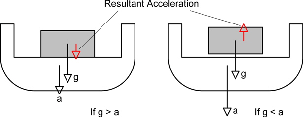
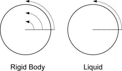
The inertia of material in a ship must be treated in different ways according to whether it is moving with the ship or not. In the case of moving with the ship, the ship’s dynamic can be analyzed under the condition that the mass of that material is included in ship’s mass. But in the case that the motion of material is different with that of the ship, the dynamics of the material and the ship must be solved concurrently and they must be coupled together to interact with each other. For example as in Fig.1 the material is on the deck of a ship and not fixed, if the downward acceleration is less than the gravitational acceleration it moves with the ship, but if the downward acceleration is greater than gravity the material fly and the mass of material is not included in the ship’s mass. For another example as in Fig. 2, when the circular cylinder accelerates in rotation, the inner liquid does not accelerate if the viscosity is neglected. In this case, the moment of inertia comes only from the circular tank and not from the liquid in it.
Under recti-linear accelerations, the liquid moves with the tank as if the liquid is frozen as a solid attached to the ship , but for a rotational acceleration the liquid has a relative motion with respect to the tank, except for the trivial case of a circular cylinder discussed above. Therefore it is needed to investigate the inner flow of the liquid to obtain the inertial properties of the liquid.
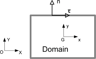
The potential flow model is assumed to analyze the inner flow of the tank. Fig. 3 shows the domain of the liquid and coordinates system.
The orientation of the normal vector is outward from the domain, and the governing equation that the flow should satisfy is the Laplace equation

and the boundary conditions on the surface of the tank.

The velocity potential is denoted by

where is the recti-linear velocity, ω r the rotational velocity vector, the position vector of the center of gravity, and the position vector from the center of gravity. The boundary condition in xy-plane can be written as follows.

The above problem is linear, so the linear superposition technique can be applied. Let us introduce the velocity potentials which satisfy the boundary conditions with unit velocity for each motion mode;

Then the velocity potential that satisfies the boundary condition Eq. (4) can be represented as follows.

The forces resulting from this flow can be expressed as in Newman (1977), chapter 4. Newman derived the formula of hydrodynamic forces to obtain added mass of a body in unbounded fluid. The same formula can be applied in the inner flow.

The above expressions can be rewritten into the forces in component.
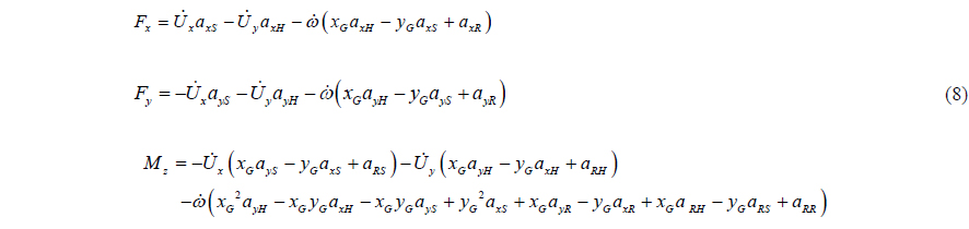
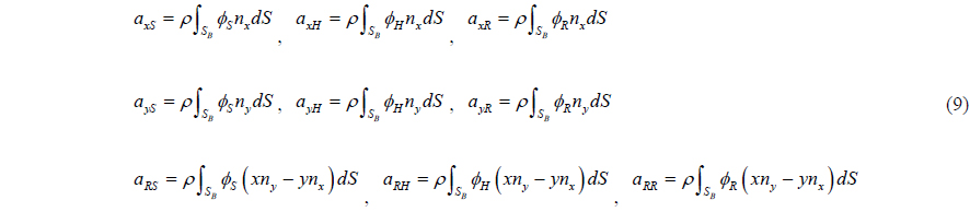
The coefficients in the above equations are as follows.

The boundary conditions in Eq. (5) are all the normal boundary conditions, so the solution of the potential problem has an arbitrary constant. And if the potential is constant, the integrals above disappear. So the arbitrary constant can be omitted for the convenience.
For the case of fully filled tank, the solutions of the above potential problem for heave and sway are the functions whose partial derivative in the direction of the motion mode are 1’s. So the potentials are

where

Substitution of the above results of Eqs. (10) and (11) into Eq. (8) leads the following inertial force expression.

Eq. (12) shows that the mass matrix has a symmetric property, and it is identical with that of rigid dynamics except the roll moment of inertia
For the roll moment of inertia, if the shape of the tank is circular, the boundary condition in Eq. (5) is vanishing on the boundary, so the potential becomes the arbitrary constant.

If the shape of tank is not circular, the non-trivial flow takes place and non-zero moment of inertia comes from that flow.
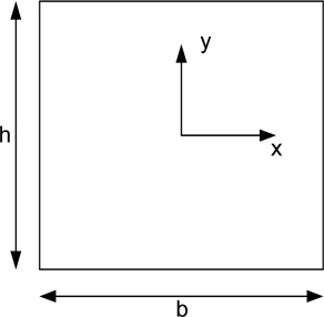
As seen in the previous section, the liquid in a circular cylinder has no roll moment of inertia provided that the origin of coordinates coincides with the center of gravity of that tank. For other than circular shape tank, it exists. Consider the roll moment of inertia for a rectangular shape tank.
When the rectangular tank undergoes roll motion, the boundary condition for the inner flow is as follows.

Condition on left boundary : −∂ϕR / ∂x = y Condition on right boundary : ∂ϕR / ∂x = −y Condition on bottom boundary : −∂ϕR / ∂y = −x Condition on top boundary : ∂ϕR / ∂y = x
From the above boundary condition, at least on the boundary, the potential has asymmetric properties. The analytic solution of this problem was obtained in Appendix A.
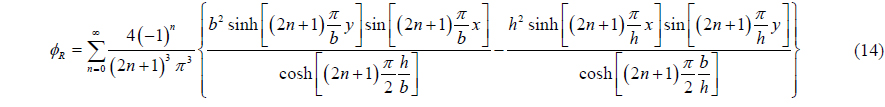
The moment of inertia was also obtained as follows.(see Appendix A.)

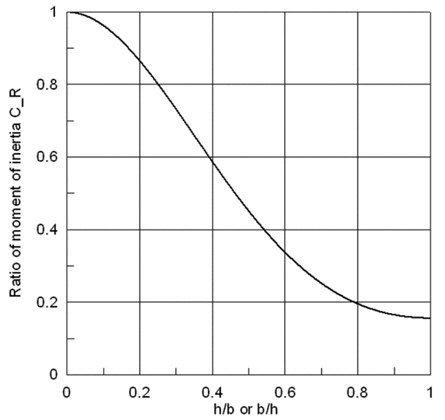
As seen in the above equation, the moment of inertia is symmetric with respect to height


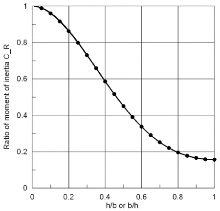
Fig. 5 shows the ratio of moment of inertia
From Fig. 5, it can be known that as the aspect ratio

where
The inner flow can also be obtained by using Green’s 2nd identity.

where
The numerically obtained values using Eq. (19) are plotted as points in Fig.6, these values agree very well with the solid line, the analytic values. The number of line segments is about 100. This agreement validates the numerical method using Eq. (19). The analytic solution can be obtained only for the special shape such as rectangle. For the other shapes, there are no analytical solutions available; the numerical solutions are presented for these cases.
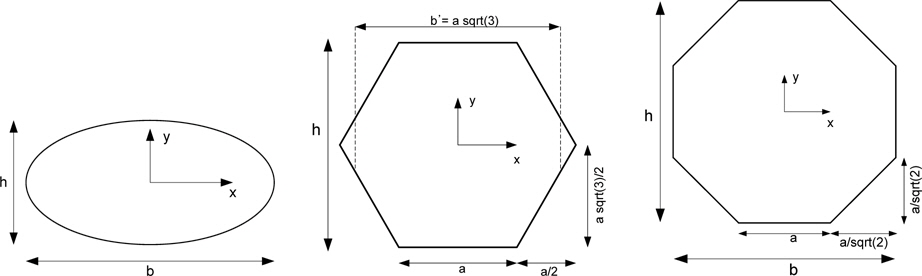
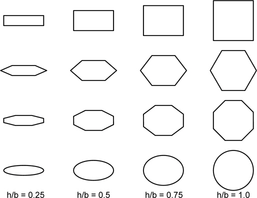
Fig. 7 shows the shapes of ellipse, hexagon, and octagon and the coordinates. In the above figures, hexagon and octagon are regular shape, i.e. equiangular and equilateral shape. In this study, the shape was modified by scaling the
[Table 1] Area and moment of inertia of solid for various shapes.
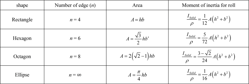
Area and moment of inertia of solid for various shapes.
Among these shapes, the moment of inertia of rectangle and ellipse are well known, but those of hexagon and octagon cannot be found even in famous textbooks, so the above formulas have been induced directly in Appendix
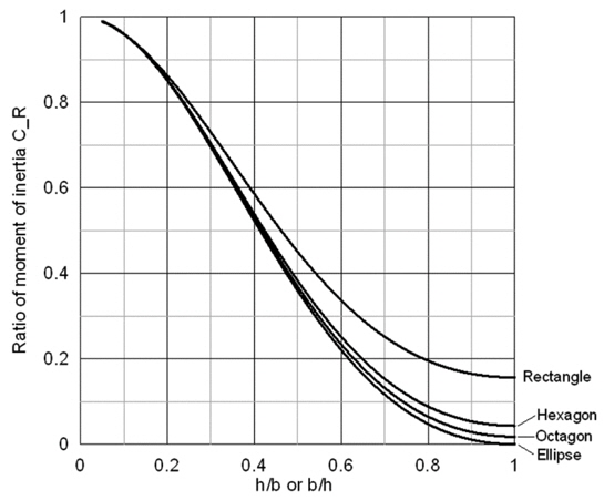
The ratios of moment of inertia for the above shapes were obtained numerically and plotted in Fig. 8.
Fig. 8 shows that the ratio of moment of inertia approaches to that of ellipse as the number of edges of tank goes large, i.e. the shape becomes ellipse. And as the aspect ratio
In this section we would like to derive an ad hoc semi-analytical formula by introducing the equivalent inner circle in the various shapes we considered here. Our finding of the final approximate formula is obtained not by a rigorous analytical procedure but through numerical experiment based on the semi-analytical results. This is why we name the present formula by an ad hoc semi-analytical approximate formula. So let’s think about an effective circle with radius
where

The moment of inertia of this circle that does not move with tank can be estimated as follows.

where

where

Therefore the moment of inertia of liquid can be estimated by following formula.

And the ratio of moment of inertia is as follows.

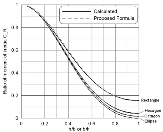
Fig. 9 shows the calculated values and the estimation value by Eq. (24). Except small difference for rectangle, the proposed estimation formula gives the very accurate moment of inertia of liquid.
The various shapes of tank that are useful for real application are shown in Fig. 10. The area, solid moment of inertia and moment of inertia of liquid can be calculated easily by using Table 1 and estimation formula Eq. (24). It might be useful in the application for the real ship.
In this paper, the inertia of the liquid fully filled in a tank is analyzed.
The inertia for the recti-linear acceleration is shown to be the mass of liquid. However for the rotational acceleration, the moment of inertia is smaller than that of solid. And the liquid in a tank whose aspect ratio of height and breadth is unity has the minimum moment of inertia compared to that of solid.
The flow and the inertia of liquid in a rectangular tank were derived analytically, and for other shape the numerical solutions were calculated. The shapes of tank investigated are ellipse, rectangle, hexagon, and octagon. And the results were given for various aspect ratios of h/b or b/h, so they can be applied practically for the problem of liquid tank in a ship.
Also presented is ad hoc semi-analytical approximate formula for practical applications to compute the moment of inertia of the liquid in a tank. This formula gives extremely accurate predictions for the moment of inertia for several tank shapes considered in the paper.
The results of this study will be useful for the calculation of inertia of a ship which has large liquid tanks, especially for the ships like LNG/LPG carriers and purified oil tankers.