We designed and implemented a fork-type automatic guided vehicle (AGV) with a laser guidance system. Most previous AGVs have used two types of guidance systems: magnet-gyro and wire guidance. However, these guidance systems have high costs, are difficult to maintain with changes in the operating environment, and can drive only a pre-determined path with installed sensors. A laser guidance system was developed for addressing these issues, but limitations including slow response time and low accuracy remain. We present a laser guidance system and control system for AGVs with laser navigation. For analyzing the performance of the proposed system, we designed and built a fork-type AGV, and performed repetitions of our experiments under the same working conditions. The results show an average positioning error of 51.76 mm between the simulated driving path and the driving path of the actual fork-type AGV. Consequently, we verified that the proposed method is effective and suitable for use in actual AGVs.
In recent years, flexible manufacturing systems have attracted considerable research interest from the field of production management. In particular, automatic guided vehicles (AGVs), which function as industrial robots, are being researched actively and are in themselves a new growth industry in several countries. AGVs can work autonomously, including performing operations such as loading and unloading, storage, and transport [1-4]. AGV development necessitates the use of localization, driving control, and path-planning techniques. Particularly, localization and driving control of AGV are important elements of autonomous techniques [5-7]. Among the techniques relevant to AGVs, positioning is the most important because all autonomous techniques are based on AGV position information [8-13]. Generally, an AGV positioning system uses a global positioning sensor in conjunction with local positioning sensors. A guidance system typically includes a positioning and a control system. Guidance systems are classified as wire guidance [14-17], magnet-gyro guidance [18] and wireless guidance systems. The inductive guidance system is the most commonly used of the wire guidance system types. Typically, an inductive guidance system’s sensor is placed on the bottom surface of an AGV, and the guidance line is placed approximately 1 cm in below the ground. The sensor detects the radio waves transmitted by the guidance line. The advantage of the system is that in an emergency, the wire’s power can be turned off to immediately stop the AGV system. The magnet–gyro guidance system is similar to the wire guidance system, but it uses a micro electro mechanical systems (MEMS) gyro and magnetic position sensor. Generally, a pair of magnets is required for every 5–10 m of AGV guide path. The magnetic position sensor calculates an AGV’s orientation for verifying whether the vehicle is on course. However, wire guidance and magnet-gyro guidance systems have high costs because they are difficult to maintain with changes in the operating environment, and can only drive a path that follows sensors embedded in the workplace floor. For overcoming these limitations, wireless guidance systems have been developed. Wireless guidance systems operate using landmarks mounted on walls, poles, machines, or the ceiling. However, laser navigation, which is the most commonly used wireless guidance system, has a slow response time and low accuracy. When the system is unable to recognize landmarks or reflectors properly as the AGV is turning or moving at high speeds, it calculates an incorrect AGV position. If the AGV is loaded with heavy equipment, incorrect position data can lead to severe problems. Therefore, a robust and accurate positioning system is required.
We propose a positioning and driving control system for AGVs with laser navigation. The positioning system uses a sensor fusion platform with an encoder, gyro, and laser navigation, whereas the driving control system uses fuzzy and proportional control. This paper is organized as follows. In Section 1, AGV guidance systems are introduced. In Section 2, the measurement system, localization system, and kinematics of the AGV used in this study are described. The actuator and sensor analysis, and driving control of the AGV are presented in Sections 3 and 4, respectively. T he experiments conducted for evaluating the proposed methods are described in Section 5. Finally, the conclusions of this study are presented in Section 4. Commonly, AGV using laser navigation system has been used various sensors at encoder, gyro, etc. for compensating above mentioned problem. The part of these AGV is changed actuator, carry type, control algorithm, etc. by purpose of use of AGV.
2. AGV With Laser Navigation System
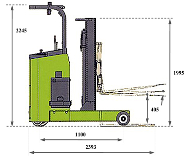
In this paper, to develop an AGV with laser navigation, we designed and built a fork-type AGV with Clark Material Handling. Figure 1 shows the forklift truck used in this study. The model name of the forklift truck is CRX-10, and it has an axle driving unit and half-electric power steering (EPS). However, the half-EPS is useful for humans. In this study, to solve the half-EPS problem, we changed it into a full-EPS with assistance from SERVCON.
2.1 Positioning and Driving Control System
The fork-type AGV’s control system consists of positioning sensors and a driving control unit. The positioning sensors include two encoders, a MEMS gyro, an electric compass, and laser navigation. The driving control unit includes a data acquisition (DAQ) system. In addition, we fabricated the fork-type AGV based on an industrial PC for flexible and rapid development. The positioning sensors were measured using an ATmega128 microcontroller unit. A NI-USB6008 DAQ was used for driving control.
2.2 Proposed Positioning Using Sensor Fusion
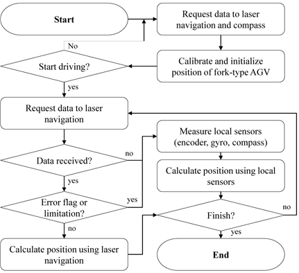
The performance of the laser navigation depends on the distance from reflectors, as well as shape and number of reflectors. The accuracy in the specification of laser navigation is about ±15 mm. However, it has a slow response time of about 425 ms. Furthermore, AGV position is calculated incorrectly in cases where the system cannot recognize the reflectors properly because the AGV is turning or moving at high speeds. However, we achieved robust and accurate position calculation through the simple sensor fusion of two encoders, a gyro, an electric compass, and laser navigation. Figure 2 shows a flowchart of the sensor fusion platform for the positioning system. The key point of our sensor fusion algorithm is the reliability calculation, which involves using error messages from laser navigation and performing stochastic interpolation by employing local sensors. We used four types of error messages (navigation operation error, distance measurement error, rotation and angular measurement error, and scan-not-right error) calculated by the laser navigation system. In addition, we experimented with sensor fusion using an extended Kalman filter (EKF). However, there was very little difference between the proposed sensor fusion approach and sensor fusion using an EKF.
3. Actuator and Sensor Analysis
Because the forklift truck used in this study was not made for AGV development, an analysis of its actuators and sensors was necessary. Therefore, this section presents the analysis results of the actuators obtained through the localization sensors.
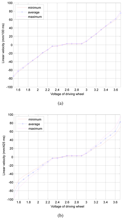
The driving actuator moves forward when the input voltage is 2.5~4.8 V, and backward otherwise. Figure 3(a) and (b) show the minimum, average, and maximum velocities recorded as the fork-type AGV travelled about 5 m in a straight line, according to the input voltage. As shown in Figure 3(a) and (b), the fork-type AGV stops when input voltage is 2.5 V and moves very slowly when the input voltage is 2.3~2.9 V. The fork-type AGV begins to move when the input voltage is less than 2.3 V or more than 2.9 V.We showed that the voltage has a linear characteristic, except between 2.3 and 2.9 V. In addition, the difference between the minimum and maximum velocities increased gradually with the increase in velocity when using the laser navigation system (Figure 3(b)). However, when using the encoder (Figure 3(a)), the difference between the minimum velocities is small in spite of the increase in velocity.
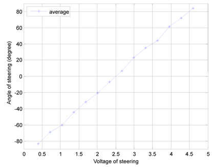
The fork-type AGV has an electric steering system operated by a gear drive having a 1 : 26 gear ratio. The steering angle range is −85°~+85°, and the input range is 0.3~4.7 V. To analyze the steering characteristics, we used the inverse kinematics calculated from the fork-type AGV’s position determined using the encoders and gyro. We were unable to use the laser guidance system because when the fork-type AGV turns, the laser navigation’s output includes a large error. Figure 4 shows the steering angle of the AGV as a function of the steering input. As shown in Figure 4, the steering angle has a linear characteristic, but there are some errors due to the small gear ratio. We designed and implemented the driving control scheme based on this analyzed data.
4. Driving Control for Fork-Type AGV
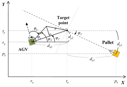
Because the transport system of the fork-type AGV is in front of body, driving control for the AGV was considered in terms of both the position and the angle of a pallet. We designed the fork-type AGV to move by 2 m in front of a pallet from the fork-type AGV’s center because the fork length is 90 cm and the fork-type AGV requires about 1 m for pallet recognition. Figure 5 shows the proposed driving method. (p
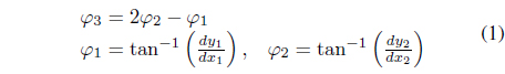
where

The driving control scheme uses the distance and the angle error between the fork-type AGV’s current position and the target position. If the angle error is −30°~+30° and requires accurate control, then fuzzy control is used. Otherwise, proportional control is used.
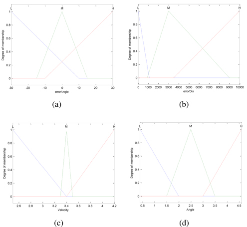
As previously mentioned, the proposed driving control consists of fuzzy control and proportional control. Proportional control uses a linear signal of angle and distance Error between the target position and the forklift’s current position when the angle and distance errors are large. The input parameters for fuzzy control as well are the angle and distance errors, and the outputs are input signals of steering actuator and driving actuator. Figure 6 shows the input membership functions and the fuzzy control output obtained using the analyzed results described in Section 3.
If the distance error is small, the output driving speed is low. Otherwise, it is high. The output steering angle signals low regardless of the distance error when the angle error is small. Table 1 shows the fuzzy rule used in this study.
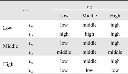
Fuzzy rule used
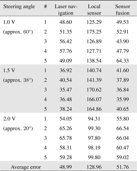
[Table 2.] Results of proposed positioning method (unit, mm)

Results of proposed positioning method (unit, mm)
The experimental space measures 850 cm × 1000 cm. The absolute coordinate is on the top-right. Fifteen reflectors (dotted-line circles) were installed for laser navigation.
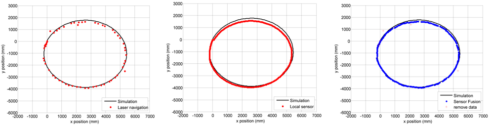
For experimentally verifying the proposed positioning system, we analyzed the positioning results by varying the steering actuator input, while keeping driving actuator driving actuator input was 3.6 V (approximately 3.0 km/h) and the steering input was 2.0 V (approximately 20°). In Figure 7, the driving start position is (0, 0), and the black input fixed. Figure 7 shows the experimental results when the line represents the simulation localization result, which did not include any error. The damage and loss of data resulting from a disturbance is apparent only when laser navigation was used (Figure 7(a)). As shown in Figure 7(c), the trajectory generated using only local sensors slants toward the outside because error is accumulated. However, the proposed positioning method compensates for the shortcomings of laser navigation and the local sensors. Table 2 lists the average positioning errors as a function of the steering angle when the driving speed of the AGV is 3.6 V (approximately 3.0 km/h). The result achieved using only laser navigation was better than those using only the local sensors and using only the proposed positioning method because the simulation result was used as reference for calculating the positioning error. It is impossible to correct the synchronization between the simulation and the actual driving. In addition, even if the AGV moved the same distance, the response time of laser navigation would be slower than those of the other methods. Therefore, we can assume that the proposed positioning method is better even if it had low accuracy.
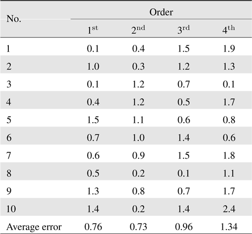
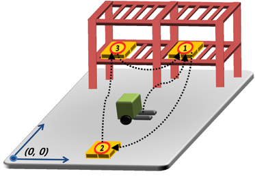
We assumed that the pallet position is sent to the AGV from the operation server. Figure 8 shows the experimental method for verifying the proposed driving control. The fork-type AGV, which is situated in a random position, autonomously moves to the No. 1 position. When the move is complete, the AGV load the pallet at the No. 1 position and unloads it at the No. 2 position. When the unloading is complete, the AGV moves to the No. 3 position and loads the pallet at the No. 3 position. inally, the AGV unloads the pallet at the No. 1 position. To analyze the performance of the proposed driving control, we analyzed the angle error between the pallet’s position and the forklift AGV’s position when the AGV arrives at the load and unload positions. We repeated the experiment ten times under the same conditions, and the results are summarized in Table 3 . As can be inferred from Table 3, the average error was 0.95° over ten repetitions, and the maximum error was 2.4°. For loading and unloading a standard pallet, the angle error of the fork-type AGV should be less than the maximum ±5° error method between the pallet’s angle and the fork-type AGV angle at a distance of 1 m in front of the pallet. Otherwise, AGV would move again after it moves backward. From the results, we verified that the proposed positioning and driving control system could be effectively applied to fork-type AGVs.
[Table 3.] Results of proposed driving control (unit, °)

Results of proposed driving control (unit, °)
We presented the design and implementation of a fork-type AGV with laser navigation and proposed a positioning and driving control scheme. The positioning system is a sensor fusion platform with encoders, gyro, electric compass, and laser navigation. The driving control system uses fuzzy and proportional control. The proposed positioning method is simple and performs efficiently. In this study, we did not describe our experiments on sensor fusion using a probabilistic prediction method, but there was very little difference between simple sensor fusion and sensor fusion using a probabilistic prediction method. Our experimental results verified that the proposed method is effective for use in actual AGVs.
No potential conflict of interest relevant to this article was reported.