The common zoom system is a multiple conjugates system allowing objects to be imaged on an image sensor with different scales. Designing a zoom lens consists of finding out the coupled motions of lens elements to accomplish the continuous variations of magnification or focal length. During the zooming, only the separations between elements vary at each zoom position. These separations are designated as an adjustment for changing magnifications and maintaining the image in focus.
Initial design methods for zoom lenses are usually divided into two ways. One is the paraxial analysis based on thin lens theory. The other is the optimized solution from lens modules design. The paraxial analysis has several disadvantages. It is difficult to judge if the solutions satisfy all the requirements for the zoom system [1-5]. Contrary to the paraxial method, since the lens module method employed in this study involves lots of physical quantities of the optical system, the first-order and thirdorder aberrations can be manipulated directly by using lens modules [6-7]. Several zoom lenses have been designed and evaluated by lens modules [8-12].
In the previous design using lens modules, the real lenses for all groups are separately designed to match the first-order quantities and aberrations of the modules. And the separately designed groups are then combined to form an actual zoom lens. In this combining process, however, the stop position of each group is changed, which generates the large off-axis aberrations due to stop shift effects [13-15]. In our work, after obtaining the lens module zoom system, the real lens groups are successively, not separately, designed to get a zoom lens system. Compared to the previous design methods [8-12], this approach can give a better starting zoom lens, and save time and effort.
In this paper, lens modules and aberration theory are used to discuss the optimum initial design of a 10x, four-group inner-focus zoom system. This initial zoom system is designed to satisfy specific requirements, and the real lenses are successively obtained from the lens modules by using an automatic design method. In order to fold the ray path, the design reported recently has the minus-power single lens and a prism [16]. In this research, however, the right-angle prism was directly inserted without any lens in front of the first group. This configuration resulted in a much slimmer zoom system than the conventional system. After balancing of the higher-order aberrations, we obtained the zoom system that has the aperture of F/3.5 at position 1 to F/4.5 at position 3 and zoom ratio of 10x.
II. LENS MODULE ZOOM SYSTEM DESIGN
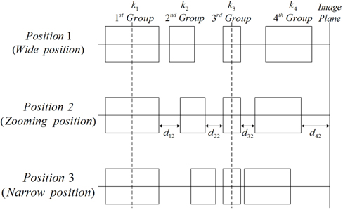
Figure 1 illustrates the four-group inner-focus zoom system. From the object to the image side, the zoom system is composed of a fixed front group, a second lens group for zooming, a fixed third lens group, and a fourth lens group for focusing. Their powers are denoted K1, K2, K3, and K4, respectively. The distances between the preceding group and the succeeding group are denoted by
Each group is generally composed of several thick lens elements. When the higher-order aberrations are neglected, the properties of the lens system can be specified by its first-order quantities and the third-order wave aberrations at given conjugate points. In other words, if the first-order quantities and the third-order aberrations of the lens module are assigned to the real lens group, then both lens systems are equivalent to each other to within the limit of the first-and the third-order properties. Hence, each group of the zoom system can be replaced by its thick lens module by specifying its focal length(FLM), front focal length(FFM), back focal length(BFM), magnification(MGM), entrance pupil position(EPM), entrance pupil diameter(EDM), field angle(β), and third-order aberrations [13, 17].
We have set up the zoom lens system with four thick-lens modules, for which initial first-order inputs are appropriately given to work as a zoom system. For the inner-focus zoom lens having high zoom ratio of 10x, the powers of the groups are generally composed such that the first, the third, and the fourth groups have positive powers, but the second group has a strong negative one. The aperture stop of the system is located in front of the third module so that the system has a symmetrical configuration with respect to the stop for aberration balancing. And then we reduced the aperture and image size of the initial zoom system so that the third-order aberrations were dominant. We have taken the zoom system with a half-image size of 1 mm and f-numbers of F/5 at position 1 to F/7 at position 3.
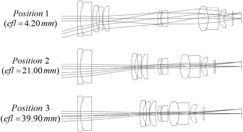
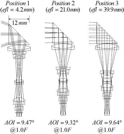
In order to get an optimum zoom system, the lens module prescriptions are optimized so that the specific constraints are satisfied. The specified constraints are the overall length of system, the equal distances between the first surface and stop at all zoom positions, focal lengths of 4.2 mm at position 1 to 39.9 mm at position 3, and good imagery. The constraint on the overall length should be as short as possible to reduce the system size. The design variables of each module are the focal lengths, the front focal lengths, the back focal lengths, the conjugate points, the spaces, and the aberration coefficients.
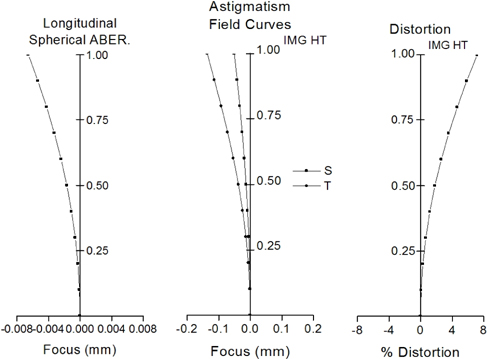
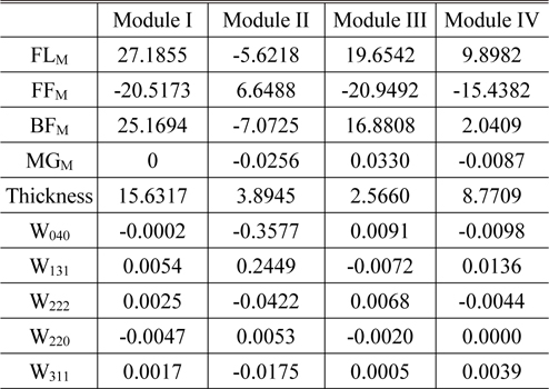
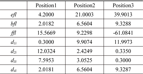
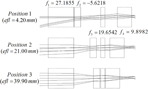
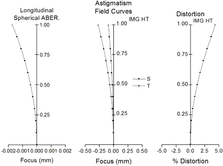
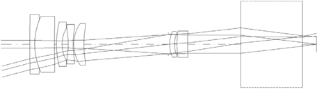
Figure 2 shows the optimum zoom system obtained from this process. It has a focal length of 4.2 to 39.9 mm, and the aberrations are corrected well, as shown in Fig. 3. Table 1 lists the design data of each module, and Table 2 gives the first-order properties and zooming locus at three positions. In Table 1, the values of
[TABLE 1.] Design data (in mm) for the lens modules in the optimized lens module zoom system

Design data (in mm) for the lens modules in the optimized lens module zoom system
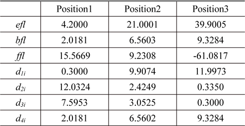
First-order properties and zooming locus of the optimized lens module zoom system consisting of four lens modules (in mm)
III. CONVERTING LENS MODULES INTO REAL LENS GROUPS SUCCESSIVELY
The conversion of the lens module into a real lens group is based on the first-order and third-order aberration properties. To calculate aberrations of each group, we must know the aberration coefficients of each group, entrance pupil diameter, reference wavelength, and Lagrangian invariant. The aberrations of each module are calculated at given f-number and wavelength of d-line by the Eqs. (1)~(6). In these equations, SA is spherical aberration, TCO is tangential coma, TAS is tangential astigmatism, SAS is sagittal astigmatism, PTB is Petzval blur, and DST is distortion [13, 17].
If we separately convert the lens modules to real lens groups and then combine them to establish an actual zoom system, as in previous works [8-11], the position of the aperture stop at each group is changed. As a result, aberrations of each group are changed except spherical aberration and Petzval curvature. In this case, we must consider the stop shift effect in calculating the aberrations, however, it is very complex [13-15]. To avoid this difficulty, we successively converted lens modules to real lens groups.
In this paper, we used an optimization method so that the real lens equivalent to the module is obtained for each group. We choose appropriate structure for the real lens group and scaled up or down so that the focal length of each real lens group is the same as that of the lens module. And using the optimization method of Code-V, we matched the first-order quantities and third-order aberrations of the lens module to those of real lens. For the converting process, the design variables of the real lens are the radius of each surface, thickness and air space between the elements, and refractive index. The constraints are composed of the four first-order quantities of each module given in Table 1 and third-order aberrations calculated by Eqs. (1)~(6).
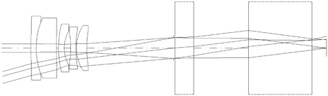
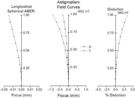
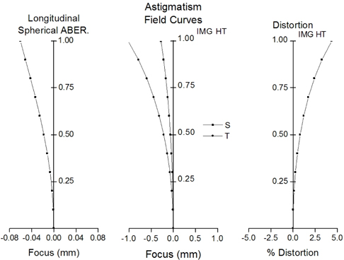
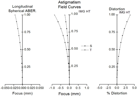
Figure 4 represents the converting process to the real lens of the first group only. Fig. 5 represents the aberrations of the system shown in Fig. 4 at position 1. At this time, other three groups are lens modules and, unlike the first group, have not been carried through the converting process. By these iterative processes, the second group, third group, and fourth group are successively converted to real lens groups. As a result, the lens module zoom system is group by group converted to the initial real lens zoom system without calculating the stop shift effect. Figure 6 represents the converting process to real lenses of the first and second groups, and Fig. 7 is the aberration of this system at position 1. Figure 8 represents converting process to real lenses of the first, second, and third groups. Figure 9 is the aberrations of the system shown in Fig. 8 at position 1. Figure 10 represents the converting process to real lenses of all groups, and Fig. 11 is the aberrations of this system at position 1. By this converting process, we have easily obtained the four real lens groups reflecting the first-order quantities and third-order aberrations of lens modules.
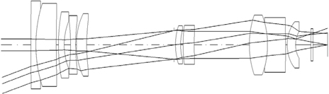
Figure 12 represents the initial real lens zoom system combined due to zooming the locus listed in Table 2. As compared Fig. 3 to Fig. 11, the differences in aberration amount between the initial real lens system and the lens module system are caused by residual aberrations which are not considered in this section. These residual aberrations can be balanced by the optimization process. However, both lens systems have very similar aberration properties. Table 3 shows the first-order quantities and zooming locus of an initial real lens zoom system. From Table 2 and Table 3, the agreement for the first-order properties between both zoom systems is complete. This design procedure results in a real lens zoom system equivalent to the lens module zoom system, as shown in Fig. 12.
[TABLE 3.] First-order properties and zooming locus of an initial real zoom system (in mm)

First-order properties and zooming locus of an initial real zoom system (in mm)
IV. OPTIMIZED DESIGN FOR A SLIM ZOOM SYSTEM
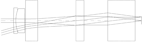
Returning to the zoom system in Fig. 12, a glass block is inserted to fold the ray path. It is located in front of the first lens, not inside the lens system. Its thickness is just 12 mm, which configuration realizes a much slimmer zoom system. Since the axial rays are parallel to optical axis, there are no aberrations induced by the prism block.
In the initial design, we reduced the aperture and the field size so that the aperture and the image size was too small. If current specifications for a zoom camera are to be met, the aperture and the field size should be increased. The f-numbers are extended to F/3.5 at position 1 and to F/4.5 at position 3. The half image size should be 2.2 mm for 1/4-inch CCD. In an extended aperture and field system, however, higher-order aberrations that are not corrected in the previous design become significant.
In order to improve the overall performance of the zoom system with an extended aperture and field, we balance the aberrations of the starting lens given in Fig. 12 by using the lens design program. In this process, the first-order layouts are fixed. To correct the residual aberrations, we use two aspheric lenses.
The third group relays the refracted ray from the second group to the fourth group. Because the stop is placed in front of the third group, the axial ray heights at that group are very high at all zoom positions. Therefore, the third group generates lots of spherical aberration. Both surfaces of this lens are aspherized to balance the spherical aberrations. The fourth group is designed into a cemented lens and a singlet. To correct the distortion, it will be generally effective to use an aspheric lens at the first group. However, the distortion and the field curvature are corrected by the aspheric surfaces at the last lens of the fourth group in this study. It is, of course, useful to correct these aberrations because the chief ray’s height in that lens is high at wide-field position.
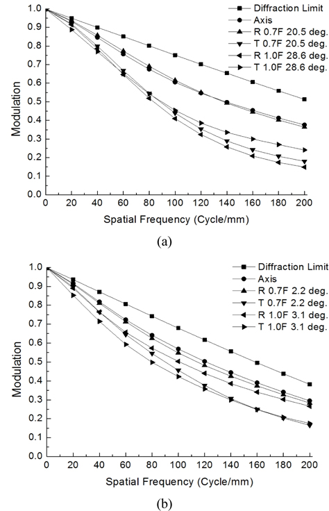
Finally, a zoom system having good performance is obtained. The layout of the system is shown in Fig. 13. Table 4 lists the prescription data of the aberration-balanced zoom system. Figure 14 shows the modulation transfer function (MTF) characteristics of the system at two extreme positions. Aberrations are significantly reduced, and the MTF at 200
[TABLE 4.] Final design data of an aberration-balanced zoom system
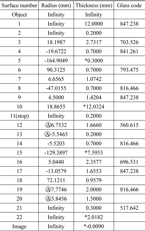
Final design data of an aberration-balanced zoom system
For four-group zoom lens design with high zoom ratio, we set up an inner-focus zoom system consisting of four lens modules with a reduced aperture and field. The optimum initial design with a zoom ratio of 10x was derived by assigning first-order quantities and third-order wave aberrations to each module along with specific constraints. In the lens module zoom system, four lens modules were converted to real lens groups step by step using an automatic design method. From this successive conversion process, the real lens of each group was quickly obtained by matching the four first-order quantities and third-order aberrations of lens modules. This design method is different from previous works in that the past method is to design all groups separately, and then they were combined to establish an actual zoom system.
A prism of 12 mm in thickness was inserted to fold the ray path, which configuration resulted in a slim zoom system having high zoom ratio. Through balancing of the higher-order aberrations in the extended aperture and field, we improved the performance of the zoom system further. A slim zoom system with a zoom ratio of 10x, whose aperture was F/3.5 at wide field and F/4.5 at narrow field, and which had an image size of 1/4-inch on a CCD, was obtained. The zoom system developed in this work performs reasonably as a slim zoom camera with high zoom ratio.