To improve the utilization efficiency of solar energy, a new solar optical concentrating system composed of a parabolic reflector with a square cross-section, a hyperbolic reflector with a square cross-section and two converging convex lenses has been designed. The proposed method can simultaneously focus and shape sun light into a square pattern on the solar panel. In addition, the total reflection property of photonic crystal within the range of the visible sunlight spectrum has been analyzed. Finally, the relationship between solar concentrating multiples and the diameter of the primary mirror has been discussed.
In the past 30 years, the development of new and renewable clean energy has become an issue common to all of the world. In order to improve the utilization efficiency of solar energy, one of the effective ways to reduce the cost of solar power is the use of a solar concentrating system [1-3]. Among the traditional optical shapes, the two stage mirrors reflective configuration has been widely utilized to improve collection efficiency and to decrease the number of expensive cells [4]. The photovoltaic cells are usually available only in rectangular shapes due to fabrication and packaging simplicity [5].
To further enhance the utilization efficiency of the square photovoltaic cell, it is necessary to generate a square light pattern by adopting a parabolic reflector with a square-beam shaping ability [6, 7]. Hence, this paper proposes a new type of solar concentrating optical system. In addition, the total reflection properties of photonic crystal within the range of the visible sun light spectrum has also been analyzed.
II. DESIGN OF THE SOLAR CONCENTRATING OPTICAL SYSTEM
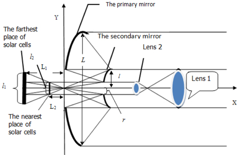
The solar concentrating optical system consists of a parabolic reflecting mirror (i.e. the primary mirror) with a square cross-section, hyperbolic reflecting mirror (i.e. the secondary mirror) with a square cross-section, two converging convex lenses and a solar panel. Different from the traditional solar concentrator, this design can shape the sunlight into a square, to just meet the rectangular configuration of solar panels. In order to make more effective use of solar energy, we design a suitable hole in the center of the secondary mirror. By calculating, the secondary mirror size should meet the condition that incident light from the outer edge of the primary mirror just reflects to the outer edge of the secondary mirror, the size of the hole in secondary mirror should meet the condition that the incident light from inner primary mirror edge just reflects to the inner edge of the secondary mirror. The practical structure diagram of the solar concentrating system is shown in Fig. 1.
We place the solar panel at the back of the primary mirror, and put two converging convex lenses in front of the secondary mirror. The two converging convex lenses are used to collect the sunlight blocked by the secondary mirror. As long as the focal point of the lens 1 and the lens 2 is overlapped, the parallel sunlight can also keep parallel after passing through the two lenses. This design makes the center of the solar panel obtain sunlight exposure, and reduces the internal energy consumption caused by uneven distribution of sunlight.
In the meridional plane, the two-dimensional curve equation of the secondary mirror can be described as:
Where
The focal point of the two-dimensional secondary mirror is (0, 0), (2
In the meridional plane, the two-dimensional curve equation of the primary mirror can be described as:
where the
where 2
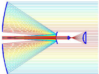
Two-dimensional simulation of the solar concentrating system is shown in Fig. 2.
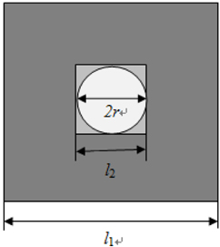
In order to guarantee that all the area of the solar panel is irradiated by sunlight, there should be no gap between the circular spot in the middle and the square spot of the periphery. The sun light which illuminates on the solar panel is shown in Fig. 3.
The bigger rectangle is the light distribution on the solar panel when the solar panel is farthest from the parabolic reflector. The smaller rectangle is the light distribution on the solar panel when the solar panel is nearest from the parabolic reflector.
As is shown in Fig. 3 , the width of the solar panel
When the width of the solar panel is maximum, the distance
When the solar panel is moved in the direction close to the primary mirror, the solar panel area is also reduced accordingly. The width of the solar panel
When the width of solar panel is minimum, the distance
We define the solar concentrating multiples as the ratio of primary mirror area and solar panel area. When the width of the solar panel is
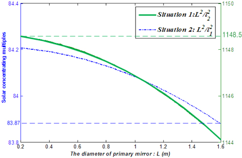
To get a concrete relationship between the concentrating multiples and the primary mirror diameter, we should determine the ratio of
The primary mirror diameter
III. PROPERTIES OF ONE-DIMENSIONAL PHOTONIC CRYSTAL TOTAL REFLECTION MEMBRANE
In this paper, the surface for the primary mirror and secondary mirror for the solar concentrating optical system are designed as a one-dimensional photonic crystal structure (the primary mirror and the secondary mirror can be seen in Fig. 1). With this kind of photonic crystal, we can realize a total refection in the sunlight wavelength region.
One-dimensional photonic crystal can be designed as a kind of periodic medium reflector with high reflectivity [8, 9]. It breaks the limits of metal reflector and periodic medium reflector for realization of low loss and omnidirectional reflection. So it can be applied in many fields such as solar power collection [10, 11].
In the TM mode, by using the Maxwell equations, the electric field can be written as [12]
where the j=1,2, correspond to the two layers of a photonic crystal media material.
The propagation constant of z direction can be described as
Where
The transfer matrix elements can be given
where
Where
By changing the refractive index and the thickness ratio of the photonic crystal, the optimized total reflection band wavelength will be obtained.
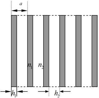
In this paper, a period of one-dimensional photonic crystal unit has been designed as two kinds of of medium material. Ratio of the refractive index between the two materials is
The part region suface structure of the photonic crystal for the primiary reflection mirror and secondary reflection mirror are shown in Fig. 5. The structure parameters of height ,width and period interval can be seen from Fig. 5.
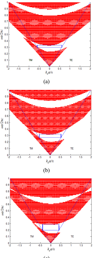
The rectangular part is a total reflection band and the red part is a photonic band gap. We design a rational structure of the photonic crystal, so that the visible sunlight range is included in the total reflection band. This kind of photonic crystal can be a light reflector for its good performance.
When we set
From Fig. 6, we can get the result that when the photonic crystal medium thickness ratio is fixed, with the increase of the ratio of dielectric refractive index, the total reflection wavelength range increases accordingly. It is indicated that, when the ratio of the refractive index between the two materials is
We have designed a new solar concentrating optical system to shape incident sun rays into a square spot for improving utilization efficiency. The solar concentrating optical system is composed of a parabolic reflecting mirror with a square cross-section, hyperbolic reflecting mirror with a square cross-section, two converging convex lenses and a solar panel. The solar concentrating multiples ranges from 83.874 times to 1148.5 times when the ratio of parameters a and b is 4:3, and with the change of primary mirror diameter, the solar concentrating multiple changes a little. In addition, when the ratio of the refractive index between the two material is