Multiwavelength Fiber laser (MFL) has been the focus of many researchers in the last two decades due to its potential application in dense wavelength division multiplexing (DWDM) communication systems [1], optical sensors [2] and spectroscopy [3]. Since then, numerous works have been reported where the aim is to improve lasing threshold, number of generated Stokes lines and tuning range [4, 5]. One method is to use high Brillouin pump (BP) where it can result in increasing the tuning range. However, the downside of this method is that it will reduce the number of generated Stokes signals. This happens because high BP will saturate the Erbium-doped fiber (EDF) gain faster [6]. Another method to enhance tuning range is by using a band pass filter and Sagnac loop mirror [7-10]. However, the filter limits the gain bandwidth thus reducing the number of generated Stokes signals and the Sagnac loop added complexity to the set up with similar output. A virtual mirror is another technique to enhance tuning range by reducing the competition with BP power through suppressing the self-lasing cavity modes again at the expense of the number of generated Stokes lines [11, 12].
Increasing the number of the Stokes line generation was another goal of many researchers [13-15]. A simple and efficient method to increase the number of generated Stokes lines was proposed by [16] insering a short length of passive EDF into the cavity. Using this technique, the number of generated Stokes lines was increased by 33% because the passive EDF section acts as an additional gain medium pumped by backward amplified spontaneous emission (ASE) from active EDF in the cavity. However, increasing the generated Stokes lines due to the inclusion of a single passive EDF booster section length was the main idea investigated in [16]. So far no passive EDF section length optimization was presented. In addition other laser cavity performance of tuning range and laser cavity threshold were not covered
In this paper, full laser cavity characteristics based on an experimental analysis of the impact of different booster section lengths to all of the performance factors of number of generated Stokes lines, tuning range and the laser cavity threshold within MBEFL is presented.
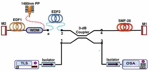
The experimental set up of the MBEFL is depicted in Fig. 1. Standard single mode fiber (SMF-28) was used as Brillouin gain medium with length of 10 km. The active medium was a 10 m EDF pumped by a 1480 nm diode laser. It was used to amplify the oscillated Brillouin pump (OBP) and it generated the Stokes signal. The Brillouin pump (BP) was provided by a tunable laser source (TLS) with output power of 10 dBm and tuning range from 1520 nm to 1620 nm. An isolator (ISO) was used to prevent any reflected light from damaging the TLS. Two highly reflective mirrors, M1 and M2, with high reflectivity of 89% were used at each end of the laser cavity. Port 3 of the 3-dB coupler was connected to optical spectrum analyser (OSA) where the results were collected.
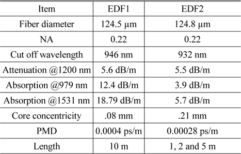
An active EDF1 with relatively high concentration of 900 ppm with an absorption coefficient of 18.79 dB/m at 1530 nm and a cut-off wavelength around 946 nm was used to achieve good flatness gain in the L-band region. A booster section (EDF2) made from a short length of EDF with normal concentration of 440 ppm, an absorption coefficient of 5.7 dB/m at 1530 nm and a cut-off wavelength around 932 nm was inserted between Port 2 of the 3-dB coupler and the wavelength division multiplexing (WDM) coupler in order to achieve an additional gain inside the cavity. This section is considered passive as it is not pumped directly by external pump power. Full specification for these two EDF sections is illustrated in Table 1. The lengths chosen were 1, 2 and 5 meters for the investigation of its impact on MBEFL performance. A set up without booster section was used as benchmark.
[TABLE 1.] EDF1 and EDF2 specifications

EDF1 and EDF2 specifications
TLS provides BP signal which is injected through Port 1 of the coupler into the SMF. The BP signal was reflected by M1 and propagated through the coupler and into EDF2 and EDF1 before being reflected again by M2. At this time, BP signal has undergone second pass amplification by EDF1 and has gone on to complete the cycle before being reflected again by M1 for another cycle. The cycle continues until the BP signal reaches the threshold point where the Stokes signal is generated. The generated Stokes signal, the first order, propagates in the opposite direction to the BP signal. Therefore it will travel to M2 and undergo double pass amplification before completing the cycle. The process goes on until the total gain is equal to the total loss contributed by devices insertion loss, SMF attenuation and EDF2 absorption. As the pump power increased, EDF2 was no longer passive because the unwanted amplified spontaneous emission (ASE) signal from EDF1 became a secondary pump which makes it an active medium [16].
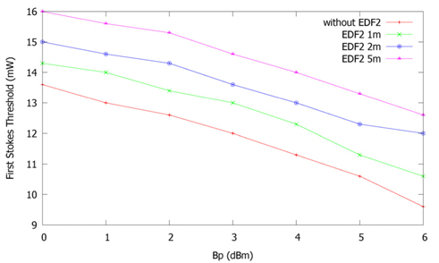
The threshold value for MBEFL with different booster section lengths is depicted in Fig. 2. The lasing threshold is defined as the amount of 1480 nm pump power at which the first Stokes signal starts to oscillate inside the cavity [5]. Referring to Fig. 1, the provided BP signal from TLS will be oscillated between M1 and M2 so it has undergone double pass amplification by EDF1 and gone on to be passed through EDF2 to complete the cycle before being reflected again by M1 for another cycle. Once the oscillated BP signal power reaches the SBS threshold value at the near end of the fiber, the first Stokes signal starts to oscillate. Thus the oscillated BP signal power mainly depends on the released gain from the EDF1 at certain 1480 pump power to compensate the losses inside the cavity so it can generate the first Stokes signal. On the other side, the introduced gain within EDF1 is strongly dependent on the amount of 1480 pump power until the gain saturates due to high pump power. Therefore, at low 1480 pump power, the introduced gain within the EDF1 is very small and the oscillated BP power gain will depends on the amount of the injected BP signal power. Subsequently higher 1480 pump power (threshold value) is needed for lower injected BP signal power as clearly seen in Fig. 2. In addition, at low 1480 pump power, the backward ASE is relatively low to pump the EDF2 section therefore at this point EDF2 works as an absorber section and by increasing EDF2 length higher 1480 pump power (threshold value) is needed to compensate any additional losses for longer EDF2 length.
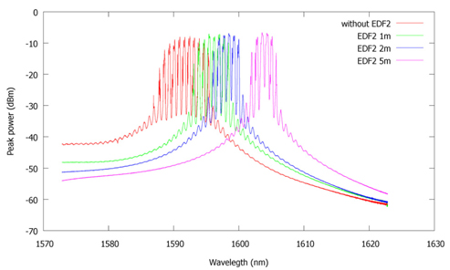
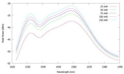
Figure 3 shows the self lasing cavity mode for the set up with and without booster section at 100 mW pump power. For the setup without booster section, the sel-flasing cavity mode is about 10 nm wide (1590-1600 nm). When the booster section was inserted, the self-lasing cavity mode shifted about 2 nm towards longer wavelength. It happens because when booster section is added, the backward ASE from EDF1 will pump EDF2 thus effectively increasing the gain in the cavity. The shift was larger as the length of EDF2 increased. Referring to [17] in which the same booster section length used in [16] is included in the cavity with contribution of variable optical attenuator (VOA). It was proved that the self-lasing cavity modes can be tuned by tuning the VOA. In other word, increasing the losses inside the cavity by increasing the VOA degree is effectively shifted the self-lasing to shorter wavelength. In contrast if we increase the total gain inside the cavity by inclusion of different passive EDF booster section lengths, the self-lasing cavity modes can be shifted to longer wavelength.
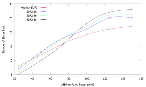
Figure 4 shows the generated Stokes signals for MBEFL with and without booster section at fixed BP of 4 mW. It can be seen from the figure that the number of generated Stokes signals increases linearly with increasing pump power, a typical feature of any fiber laser. At low pump power of 25 mW, all passive EDF2 section lengths act as absorber sections and introduce additional losses inside the cavity which resulted in Stokes lines limitation and show fewer generated Stokes lines compared to the conventional BEFL cavity setup. This is because at such low pump power, the released backward broadband ASE (1520-1570 nm) within EDF1 is inadequate to be used as a secondary pump for EDF2 section. As the pump power increased to 50 mW, the broadband ASE becomes sufficient to be used as a secondary pump for L-band Stokes signal amplification in 1m EDF2. Therefore the laser cavity with booster section exhibits higher Stokes lines comparing to the conventional cavity. On the other side, longer EDF2 section lengths of 2 m and 5 m still show fewer Stokes lines. For 1480 pump powers greater than 80 mW, all the EDF2 section lengths demonstrate an increment in the number of generated Stokes lines as compared to the traditional BEFL cavity. In this case, the relatively high 1480 pump powers can produce a sufficient amount of backward ASE so it can be used as a secondary pump for Stokes signals’ amplification in all EDF2 section lengths. Moreover, higher amplification can be achieved in longer EDF2 section length which subsequently produces higher Stokes lines numbers.
By inserting the EDF booster section, the higher energy of shorter backward ASE wavelengths photons were absorbed and re-emitted in low energy power with longer wavelength. These two different energy levels can regarded as a quasi-two level laser system [18]. These two energy levels can be considered as an individual energy level according to the Boltzmann’s distribution among the population distribution between sub-levels [19]. Therefore, the L-band Stokes signals amplification can be achieved within the EDF2 section. Beside that, the absorption peak of the EDF2 section at 1530nm is another reason it has greater absorption for shorter backward ASE wavelengths as compared to longer Stokes lines wavelengths.
To measure the released backward ASE at different 1480 pump powers, passive EDF2 and the optical mirror M2 were removed and the backward ASE was measured at port 3 of the optical coupler using OSA as shown in Fig. 5. This measured power represents the induced ASE within the active EDF1 that was inserted to the different passive EDF2 booster section lengths after including the losses produced by the optical coupler (3 dB) and the optical isolator (0.8dB). It is clearly seen that as the 1480 pump power increases, the induced backward ASE power was increased. This power increment proves the Stokes lines increment within each passive EDF2 length that is shown in Fig. 4.
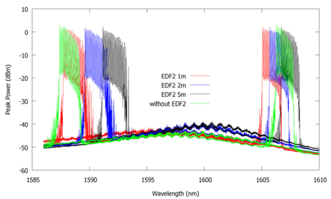
Figure 6 shows the magnified output spectrum at the start and the end of the operating wavelength range in the absence of self-lasing cavity modes for the cases of without and with different booster section lengths at fixed BP and 1480 pump powers of 4mW and 100mW. It is quite clear that by inserting booster section, the output spectrum is effectively shifted to the longer wavelength region. The wavelength shift increases with the increment of the booster section length. The reason can be attributed to the self-lasing cavity modes shifting as illustrated in Fig. 3. It is also observed that as the booster section length increased, the tuning range was reduced from 17nm to 14nm comparing to the 19nm in the conventional BEFL cavity. It is because longer booster section length will produce higher additional backward ASE inside the cavity although it provides higher gain and generates further Stokes lines.
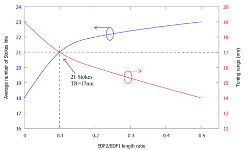
In order to optimize the length of passive EDF2, Fig. 7 shows the average number of Stokes lines and the tuning range at different length ratios between EDF2 and EDF1. The average number was taken as the number of the generated Stokes lines. It is not fixed and it is especially less so at the starting and the far edge of the operating wavelength. The length of EDF2 is changed from 1 m to 5m while the EDF1 was fixed at 10 m. The 1480 nm pump power and BP power are fixed at 100 mW and 4 mW, respectively. It can be seen from the results that the number of the generated Stokes lines increases as the length ratio increase (EDF2 length increase), as a results of an additional gain provided by a section of EDF2. On the other hand, the tuning range reduces as the length ratio increases, as a result of the higher ASE released within longer EDF2 length. The increment in the number of generated Stokes lines was at the expense of less tuning range. At 0.5 lengths ratio, an average number 24 Stokes lines with a tuning range of 14nm are obtained. In addition, at 0.1 length ratio, the recorded Stokes line was 21 over a tuning range of 17nm. Therefore, to generate maximum Stokes line number over a wide tuning range the balancing between EDF1 and EDF2 is very important.
The influence of the passive EDF booster section on the performance parameters of the linear cavity L-band MBEFL was presented. Different passive fiber lengths were used. Comparison with conventional MBEFL cavity in terms of number of generated Stokes, tuning range, and the cavity lasing threshold were made. It proves that the booster section length can play an important role in enhancing the performance of MBEFL. In other word, the balance between these two EDF sections inside the cavity is very important in order to enhance both the number of generated Stokes lines and the tuning range.