Raman amplification has been assuredly a simple single platform for wideband long-haul and ultra long-haul amplification needs. Recently, there has been great interest in using single mode fibers for high-bit-rate transmission in low-loss-transmission windows but dispersion is an important impairment that degrades overall system performance of an optical communication system [1]. In recent years, Raman Fiber Amplifiers (RFAs) have attracted more and more attention because of their flat and wider amplification bandwidth [2]. There is signal degradation due to nonlinear effects [3, 4] like Self-Phase Modulation (SPM), Cross-Phase Modulation (XPM), Four-Wave Mixing (FWM), Stimulated Raman Scattering (SRS) and Stimulated Brillouin Scattering (SBS). However, in a well-designed system these effects can be minimized. Raman amplifiers can provide better results for L band amplification and better gain flattening because they can substantially reduce the impact of fiber nonlinearity [5]. Raman amplifiers have also been used for dense wavelength division multiplexed (DWDM) systems at high bit rates [6, 7]. In [8, 9] we have investigated the DWDM system at 10 Gbps data rate / channel. In fact, the performance of a DWDM system with 0.2 nm channel spacing at 10 Gbps data rate / channel has also been observed [10]. Unfortunately, in the above reported work, the optimization of RFA has not been done. In literature various local and global optimization techniques are presented to optimize the Raman amplifier, but multi parameter optimization has not done yet. Farzin et. al [11] proposed an optimization algorithm based on particle swarm optimization in order to obtain optimized gain ripple < 0.5 dB) for S-band Raman amplifiers. But the optimization has not been done for broadband RFA. Gustavo et. al [12] proposed an accurate method for a Raman Amplifier model for extended C and C+L band by combining a hybrid genetic algorithm with a geometric compensation technique and determined pump wavelengths and powers using minimum number of pumps intended to meet the specifications. In [13], Carmelo et. al presented another multi-objective particle swarm optimizer to define the number of pump lasers and their wavelengths and powers. While multiparameter optimization was adopted for RFA in [12, 13], but the Raman length was not optimized in parallel. In spite of the numerous works on the optimization of RFA, researchers had not shown much optimization work for channel spacing below 100 GHz. In regards to extensively increasing data traffic, there is a need to increase transmission bandwidth as well as enriching the number of channels. The number of channels can be expanded by reducing channel spacing up to 0.2 nm (25 GHz). Hence, considering the scope of the above literature, still there is a need to take the following aspects into account: The multi-parameter optimization of RFA for broadband has not been considered to a great extent. Also, not much work has been reported for optimization of RFA at 25 GHz channel spacing for DWDM systems. In addition to these, the reported research has not considered optimization of the Raman length. In the literature, for broadband amplification, more than two pumps are used which leads to an increased cost.
The original contribution of this paper is to present a simple GA for multi-parameter optimization of RFA in 320 channel broadband DWDM system at reduced channel spacing (25 GHz). Our main goal is to obtain maximum gain for the amplifier by obtaining optimum values of the Raman length, pump powers and pump frequencies of two counter-propagating pumps. This paper is organized into following sections: After the introduction in Section 1 of the paper, Section 2 elaborates the RFA model for the WDM system. Section 3 describes the basic genetic algorithm and its implementation for multi parameter optimization. Section 4 presents the simulation setup. In Section 5, the results are discussed. Finally, conclusions are drawn in Section 6.
II. RFA MATHEMATICAL MODEL FOR WDM SYSTEM
Amplification in RFA is achieved through the Raman effect mechanism [14]. Raman amplifiers utilize pumps to impart a transfer of energy from the pumps to the signals to be transmitted. The broad bandwidth of RFA enables amplifying several channels simultaneously. The following system of coupled nonlinear equations can be used to describe the wave propagation in the backward-pumped fiber Raman amplifier with multiple signals and pump channels [15]
where s=1,2,……,n + m. In the above equation (1), n is the number of pump waves, m is the number of signal channels. Here, Ps, vs and
The Raman gain coefficients g(
where Aeff is the effective fiber area, and Keff is the polarization factor. Here, gi (Δv) is the Raman gain spectrum measured at the pump frequency vi. As smaller and smaller channel spacings are becoming available, so the number of channels is not limited. Gain bandwidth is over 40 THz wide, with a dominant peak near 13.2 THz (which corresponds to approximately 100 nm) [14]. Hence, the various parameters of RFA for multiple signals are optimally chosen to achieve better performance in terms of gain over the entire band in use and to make the system cost effective. However, the net amplification factor for every signal channel can be described as [15]
where s=n + 1, n + 2, ……. , n + m; (for p=1,2,…..n + m), is the power integral of the pump and other signal channels. This equation is used to calculate the gain while multi parameters are optimized using GA. In our calculation it is assumed that Aeff = 55 μm2, Keff = 2 and
III. GENETIC ALGORITHM AND ITS IMPLEMENTATION
The GA is a global search optimization algorithm based on biological evolution. It allows a population composed of many individuals to evolve to a state that maximizes the “fitness” under specified selection rules. The introduction, rules and implementation can be found in [16-18].
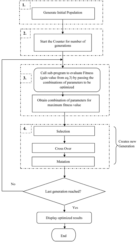
Applying this simple GA for gain optimization of RFA can be broadly sub-divided into the following steps and their sequence can be represented by a flow diagram as shown in Fig. 1.
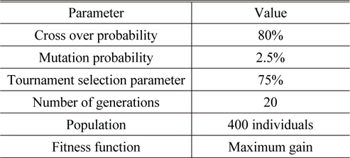
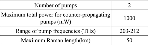
Step 1: Initialization of GA parameters and population for various system parameters i.e. Raman length, pump power level and pump frequencies. Since the two pumps are optimized for their power and frequency, along with Raman length, hence in all there are five parameters to be optimized. During this stage, the range for the parameters i.e. the limits of the search space is defined. The parameters for the GA and range of values for RFA parameters are as given in Tables 1 and 2 respectively. Set the number of generations after which the algorithm will converge and will provide the optimum solution.
[TABLE 1.] Parameters for the GA

Parameters for the GA
[TABLE 2.] Range of values for RFA system parameters

Range of values for RFA system parameters
Step 2: At this stage, the counter is started for the number of generations at the beginning. The generations proceed iteratively until the final generation is reached.
Step 3: Within the above counter established for number of generations, there are sub-stages to evaluate the fitness value and then modify the set of parameters for achieving maximum gain. Evaluation of average amplifier gain for various possible combinations of parameters is performed by calling RFA model as a sub-program. The set of parameters obtained from a randomly generated population are passed within the function call to the sub-program one by one for the whole population.
This sub-program, on receiving the combination of all the parameters to be optimized, evaluates and returns the average gain of all the channels to the main program. The current fitness value is compared with the previous fitness and if it is greater than the previous one, then the set of parameters is taken as the better solution. The previous combination is discarded and new combination is tracked during the current generation by comparing the previous results, in the form of gain, with the current one.
Step 4: During the next sub-stage, the current population of individuals is modified by appropriately employing tournament selection. The fitness value and tournament select probability are passed to call the function. Here the fitness is an array of gain values corresponding to the set of all parameters in the current population. Tournament selection chooses a random value for chromosomes depending upon small probability as defined in Table 1. New chromosome pairs are obtained from these selected chromosomes by the crossover method. These newly generated chromosomes form a temporary new population which replaces the original population after performing a mutation operation on each of the new chromosomes. Finally a new improved population is obtained.
Again step 3 followed by 4 is repeated until the final generation is reached. It can be determined that amplifier gain increases with the succession of the generations. Since the proposed method of employing GA includes tournament selection, crossover method and mutation adopted collectively, so it converges towards maximum gain in a few generations and then further modification is not desirable.
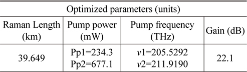
The optimum solution provided for RFA is as shown in Table 3.
[TABLE 3.] Optimized results for RFA

Optimized results for RFA
The average gain is 22.1 dB with total pump power less than 1 W. It is observed that the lower pump frequency attains a lower power level as compared to the higher pump frequency. The set of optimized pump frequencies lies almost 13.2 THz offset from the signal frequency band, which is in agreement with [14], so as to provide peak gain.
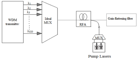
In this section, we are considering the optimized parameters to take the advantage of the optimal solution. For the validation purpose, the simulation setup established in OptiSystem software is as shown in Fig. 2. The simulation setup consists of a 320 channel DWDM system covering the broad bandwidth starting from 1578 nm to 1515 nm in a 25 GHz (0.2 nm) interval as shown in Fig. 2. Where 1578 nm is 190 THz (first channel), 1577.8 nm is 190.025 THz (second channel) and 1515 nm is 197.975 THz (last channel). Here, NRZ modulation format is used with the data rate of 10 Gbps / channel.
We have investigated this system with -30 dBm power/channel. These signals are multiplexed and fed to RFA. The RFA has length of 39.6 km employing two counter propagating pump lasers operating at the 205.5 THz (1458.8 nm), 211.9 THz (1414.78 nm) with pump powers 234.3 mW and 677.1 mW respectively. The gain flattening filter (GFF) helps to equalize the gain spectrum by reducing the tilt with the aid of introducing attenuation.
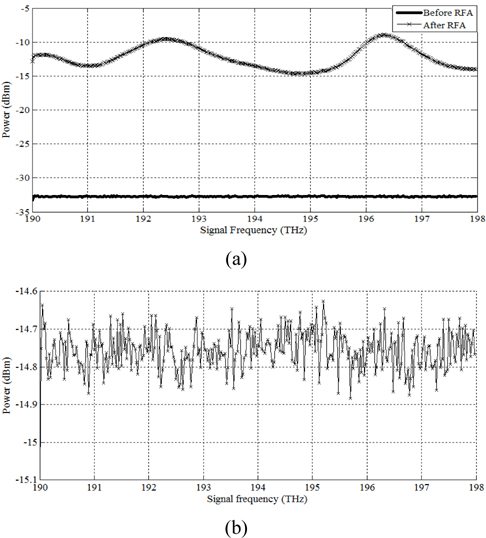
Using optimized parameters, the gain ripple observed across a wide bandwidth of around 8 THz is ~5.6 dB. Further improvement is obtained by using GFF optimization which results in reducing gain ripple below 0.5 dB. The outcomes before and after GFF optimization are shown in Fig. 3, in terms of the power level of all of the signals propagating along the Raman fiber. The power spectrum for all of the channels is smooth before RFA, however after RFA, a large variation in power levels is observed as shown by Fig. 3 (a). This is due to the fact that the pump signals do not impart equal energy to all of the channels while propagating in the fiber.
From the plot in Fig. 3(b), it is clearly observed that tilt in the power level is reduced to some extent and nearly a smooth power spectrum is obtained after GFF optimization because the sensitivity to the input power levels could change the GFF shape. In the case of DWDM systems, especially having narrow channel spacing such as 0.2 nm channel interval, nonlinear effects surpass and they are comparable to the power levels of input signals. Since GFF is a passive component with no active gain added to the system, it only decreases the amplification to match with the lowest gain within the whole optimization range. The flatness in the spectrum is achieved with the advent of introducing attenuation chosen specifically for each signal frequency during the GFF optimization.
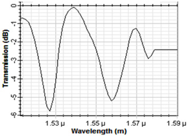
The transmission values attained by GFF are as seen in Fig. 4. The attenuation introduced across all the channels is between -6 dB to 0 dB. It shows that a high negative transmission coefficient is needed for the signal frequencies with a higher output power while the lower power levels are assigned with a lesser negative transmission value.
The optimization results for RFA and GFF can be more clearly analyzed from the plot of the gain versus signal frequencies for the two cases: without and with GFF optimization.
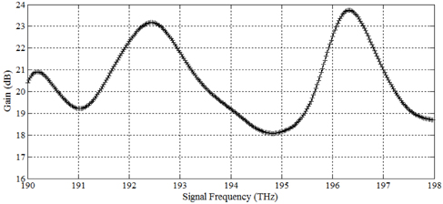
Figure 5 shows that the peak gain is observed at the signal frequencies which are offset by about 13 THz from the pump frequencies. In this case, the optimized frequencies are ν1=205.5 THz and ν2=211.9 THz, hence the gain peak is observed near 192.5 THz and 196.5 THz for the optimized pumps respectively. But deep gain dips are obtained for the frequencies at the upper extreme of the channel band. The dip in the gain at higher signal frequencies is due to rapid depletion of the higher frequency pump with transfer of power to lower frequency pump as described in [19]. The added power in the low frequency pumps causes an excessive gain at the lower signal frequencies. In contrast to this, the gain spectrum is appreciably smoothened by using GFF optimization. It leads to gain ripple of less than 0.5 dB over the entire band, but the average gain is noticeably reduced to be around 18 dB.
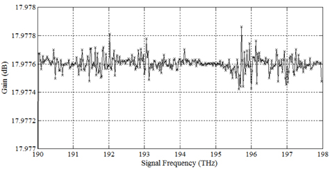
Figure 6 shows the plot for gain versus signal frequency after GFF optimization. The plot shows that the gain ripple is reduced to a great extent and it is noticeably below 0.5 dB.
Further we compare the important performance parameters (output and input) of the investigated system with current state-of-the-art schemes, as described in Table 4. This comparison has been done to determine the level of knowledge and the improvement achieved with this technique.
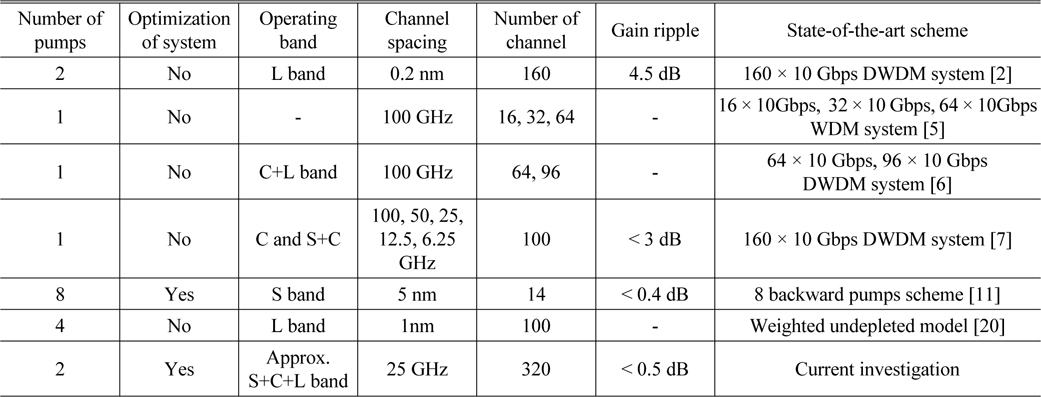
[TABLE 4.] Comparison of the current investigation with the state-of-the-art schemes

Comparison of the current investigation with the state-of-the-art schemes
In Table 4, we present currently published 2012 to 2013 snapshots of the various amplifier state-of-the-art schemes. From this table, it can be concluded that our method shows improvement over current state-of-the-art schemes because: (1) we achieved cost effective system with minimum utilization of pumps, since two pumps are used; (2) the reported results are conducted for DWDM system with 25 GHz channel spacing; (3) multi parameter optimization has been done; (4) it provided high average gain; (5) we have achieved a high capacity broadband DWDM system with 320 channels. From this survey, it can be observed that the performance of the DWDM system employing RFA can be extended by optimizing the various parameters.
A simple genetic algorithm is implemented to achieve multi-parameter optimization of RFA for broadband DWDM system at 25 GHz interval. The algorithm has proven to be accurate to refine the search of Raman fiber length, frequencies and powers of pump. It optimized Raman length to 39.6 km and pump configuration to powers of 234.3 mW, 677.1 mW with optimum pump frequencies 205.5 THz, 211.9 THz respectively. The optimized results fit the requirement of a high average gain (> 22 dB). By considering GFF optimization in this optimized system, the flatness of the gain spectrum can be increased (with ripple < 0.5 dB). With this optimized set of parameters, a cost effective solution employing only two pumps is achieved for 320 channel wide band amplification.