검색 전체 메뉴
PDF
맨 위로
OA 학술지
Two-step Holographic Imaging Method based on Single-pixel Compressive Imaging
  • 비영리 CC BY-NC
  • 비영리 CC BY-NC
ABSTRACT
Two-step Holographic Imaging Method based on Single-pixel Compressive Imaging
KEYWORD
Holography , Two-step-only , Compressive sensing
  • I. INTRODUCTION

    Over the past several years, the huge storage and bandwidth requirements for storing or transmitting holographic data has been a main limiting factor for application of digital hologram technology [1-4]. Fortunately, the newly developed theory known as compressive sensing (CS) [5-7] provides a new direction for imaging system designs. One of the most influential hardware realizations of imaging systems is the CS-based single-pixel camera [8, 9]. Based on compressive sensing, many new applications have already sprung up in the realm of holography. The group of The Duke Imaging and Spectroscopy Program (DISP) first formulated hologram data compression as a compressive sensing problem [10]. Then we may mention on-line compressive holography [11-13], off-axis compressive Fresnel holography [14], compressive incoherent holography [15-16], compressive single exposure on line holography [17]. In the optical domain, few applications of this singlepixel imaging setup in digital holography extending to the coherent regime have been reported although many successful applications of compressive sensing for holography have been demonstrated [11-17].

    To fully exploit the advantages of CS theory and holography, we develop a new holographic imaging scheme combining the CS-based single-pixel-camera with holography in the optical domain. Here, we use phase-shifting holography to generate holograms of an object, and then address the acquisition step by measuring the inner products between the hologram and the pseudo-random binary patterns generated by a digital micro-mirror device (DMD). With this method, we can directly acquire the compressed hologram using a photodiode, and never need the CMOS or CCD to record the hologram during the acquisition step. Then the acquired data is processed to produce a reconstruction of the object using reconstruction algorithms of CS. Our team has demonstrated the feasibility of the optical image recovery of four-step phase-shifting holography based on compressive sensing [18-19]. A proof-of-concept experiment evaluating the phase distribution of an ophthalmic lens with three step compressive phase-shifting holography is provided [20]. But it is necessary to record a lot of data with imaging architecture and spend a lot of time conducting an experiment. To overcome this drawback, on the basis of the method of four-step phase shifting holography based on a CS, we propose the establishment of two-step phase shifting holography based on CS, in which half of the data is recorded to reconstruct the original object, speed of the reconstruction time is faster than the four step method. Moreover, when making use of our imaging system to simulate digital holographic imaging, we get holograms generated by the phase-shift digital hologram principle, in this process we use Fresnel to get similar holograms. In the process of recording data of holograms, we can directly acquire the compressed hologram using a photodiode. However, we reconstruct the original object using the compressed hologram rather than directly using holograms generated by the phase-shift digital hologram principle. The data need experience a lossy compression process. Because half of data is reduced in two-step phase shifting holographic method compared with four-step phase shifting holographic method, in two-step phase shifting holographic method error caused by a lossy compression process will be less, real-time performance is also better than four-step phase shifting holographic method. We reconstruct the original object using corresponding hologram algorithm instead of four-step phase shifting algorithm, simulation results demonstate that reconstruction quality of image is better than four-step phase shifting holographic method.

    II. COMPRESSIVE SENSING

    Compressive sensing combines sampling and compression into a single non-adaptive linear measurement process. It is mainly made up of three sections: sparse representation, random projection and reconstruction. This subsection presents a very brief CS overview necessary for the following sections.

    Suppose that a basis matrix φ with size N × N can provide a K-sparse representation for a real value signal (e.g., image signal) X with length N. We can write

    A with length N can be well approximated using only KN non-zero entries. Let us define the acquisition model by

    X is the input object, Y with size M ×1 is our measurement, and Φ is an M × N measurement matrix, which is incoherent with φ . The goal is to reconstruct Y from few measurements. One can recover X from Y only from M = O(K log N), where K is the number of non-zero elements in A ( A =φT X ) and N is the total number of object pixels. As demonstrated in [5-7], we can recover x from y via 1 l norm optimization problem:

    III. COMPRESSIVE HOLOGRAPHIC IMAGING SYSTEM BASED ON COMPRESSIVE SENSING

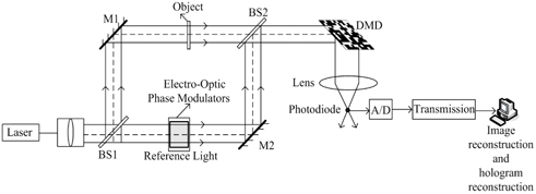
    Our holographic imaging setup based on CS theory is shown in Fig. 1. Where a linearly polarized laser beam is expanded, collimated, and then divided into an object beam and a reference beam. The phase of the reference wave is controlled by an electro-optic phase modulator. Then the two waves overlap to form interferograms. A traditional hologram generating device is different in that a single-pixel camera based on CS theory is used to collect signal and compress data in our system. We adopt a Digital Micro-mirror Device(DMD) for producing the measurement matrix Φ and computing random linear measurements of the interferograms IH and the measurement matrix Φ. We can directly acquire the compressed hologram to obtain the compressed data Y using a photodiode.

    In the case of the two-step algorithm [23] based on the traditional two-step quadrature phase-shifting holography [21-22], when we set the phases of the reference wave in the first and second exposure to 0 and respectively by regulating the electro-optic phase modulator, then two quadrature-phase holograms IH1 and IH2 are recorded sequentially on the DMD and expressed as

    IH ( xH , yH ) is a record of the interference between a reference field ur and an object scattered field uH . urk = Ar exp(rk ) , k=1, 2, Ar and φrk are the amplitude and phase of the reference wave respectively. I0 is the zeroorder light given by

    The DMD consists of many micro-mirrors, each mirror corresponds to a particular pixel in X and ϕm and can be independently oriented either towards lens (corresponding to one at that pixel in ϕm ) or away from the lens (corresponding to a zero at that pixel in ϕm ). Here ϕm can be considered as rows to form the random measurement matrix Φ(Φ = [ϕ1ϕ2... ϕM]TRM×N). When the hologram IH = (xH, yH ) produced in our setup formed on the DMD, the biconvex lens is used to collect the reflected light, and then it is focused onto a photodiode that integrates the product ϕm X to compute the measurement ym = ϕm X as its output voltage. m∈{1,2,3,...,M} .

    To compute CS randomized measurements Y =ΦX=Φφ A =[ y1y2...yM ]T , we set the mirror orientations φm randomly using a pseudorandom number generator, measure ym , and then repeat the process M times to obtain the measurement Y(Φ is the measurement matrix generated by the DMD).

    Y is the measurement data, YR M ×2 , 1HkR N ×1, Φ∈ R M ×N . The optical signal was transformed to a digital signal by a photodiode and transmited through conventional channels to the computer. Then we can reconstruct the interference wave intensity by solving a CS reconstruction problem in the computer. According to CS, we can get the optimal estimation by solving the following convex optimization problem:

    Since the hologram is piecewise constant with large gradient at the edge, we adopt a Total Variation(TV) algorithm to measure the l1 norm as:

    Here we adopt the l1 _ magic to solve this optimization problem. Then we need to compute uH(xH , yH ) ( the complex amplitude of the object optical field) by putting the optimal estimation , together. Finally we can get the original object image by the inverse Fresnel transformation. Now we will compute uH(xH , yH ) as follows. We show such an algorithm, which determines the reference wave intensity directly from the hologram without the actual need to record the reference wave intensity at all. From holographic imaging principle, should be within 0 and the maximum of IH1 . Now we construct a 2-D correlation coefficient, called CC [23].

    In Eq. (11), abs (.) denotes the amplitude of (.); Er is the image decrypted by IH1 and the correct keys; E denotes the decrypted image with two holograms and the correct keys, which is calculated by the assumed values (the value is gotten by searching from 0 to max (IH1 ) without actual measurements) of the reference light Eq. (15) and Eq. (16). We then draw the curve of CC versus Arc and set the criterion such that the minimum point of the curve locates the actual value of Ar . The algorithm can be expressed as follows:

    Ar in Eq. (4), Eq. (5) and Eq. (6) was replaced by Arc in this algorithm, then we construct a complex hologram IC as shown above. In the formula, uH = Re(uH ) + iIm(uH ) . By taking square of the absolute value of both sides of Eq. (12), we obtain the solution to a quadratic equation in I0 :

    Transposing and rearranging Eq. (4) and Eq. (5), we can write

    The quantity, F( F = Arc + Re(uH ) + Im(uH ) ), will be positive everywhere if the intensity of reference light is large than that of the object wave intensity, which is generally true in practice [23], so the minus sign should be chosen for Eq. (13). Then we can calculate

    we can calculate the complex amplitude from Eq. (12)

    Putting the optimal value , calculated from the above with CS theory into Eq. (16)

    Finally we can get the original object image by the inverse Fresnel transformation.

    IV. COMPUTER SIMULATIONS

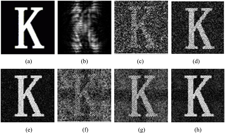
    In the following, we made a series of computer simulations to verify the effectiveness of our method. The object we used was grayscale image “K” as shown in Fig. 2(a) with 64× 64 pixels (hence, N=4096). The measurement matrix Φ generated by the DMD is random sequences of 0/1. The hologram uH (xH , yH ) was digitized shown in Fig. 2(b). When we took 2048 measurements and 3276 measurements, we respectively got the reconstruction of the original image “K” shown in Fig. 2(c) and Fig. 2(d) using the method of four-step phase-shifting holography based on CS. When we took 3686 measurements, we got the reconstruction of the original image “K” shown in Fig. 2(e) using the method of four-step phase-shifting holography based on CS. When we took 2457 measurements and 3276 measurements, we respectively got the reconstruction of the original image “K” shown in Fig. 2(f) and Fig. 2(g) using the method of two-step phase-shifting holography based on CS. When we took 3686 measurements, we got the reconstruction of the original image “K” shown in Fig. 2(h) using the method of two-step phase-shifting holography based on CS. According to the simulation results, it is clear that the new holographic imaging method we propose is feasible. We can see that there is ambiguous noise in Fig. 2(h), because we reconstruct the original object using the compressed hologram rather than directly using two holograms generated by the phase-shift digital hologram principle. The data experiences a lossy compression process.

    Fig. 2. The simulation results using our architecture. (a) Original image of letter K. (b) Digital hologram of letter K. (c) Reconstruction from 2048 (50%) measurements using the method of four-step phase shifting holography based on compressive sensing (CS). (d) Reconstruction from 3276 (80%)) measurements using the method of four-step phase shifting holography based on CS. (e) Reconstruction from 3686 (90%) measurements using the method of four-step phase shifting holography based on CS. (f) Reconstruction from 2457 (60%) measurements using current method of two-step phase shifting holography based on CS. (g) Reconstruction from 3276 (80%) measurements using current method of two-step phase shifting holography based on CS. (h) Reconstruction from 3686 (90%) measurements using current method of two-step phase shifting holography based on CS.

    V. CONCLUSION

    In this paper, we reconstruct an original image by recording two holograms in the optical domain using certain signal recovery algorithms of CS theory and hologram reconstruction techniques, which greatly enhances the hologram photography and recovery efficiency. First, we can directly acquire the compressed hologram using a photodiode and never need the CMOS or CCD to record the hologram during the acquisition step, which reduces the complexity and size of holographic imaging devices. In addition, speed of the reconstruction time is faster than the four step method. Real-time performance in two-step phase shifting is also better than that in four-step phase shifting. It will make coherent dynamic imaging possible. Our method is useful for substantially reducing the bandwidth or storage requirements of detector pixels and the scanning effort in the acquisition step. The most significant advantage about the holographic imaging system design is the enhancement of detector efficiency, because only significant components in the images’ transformed space, which are important for people’s visual perception, are collected. Our current work involves improving the quality of the image reconstruction according to the feature of hologram and CS theory, in the meantime, we are building an experimental platform for verification.

참고문헌
  • 1. Naughton T. J, Javidi B 2004 “Compression of encrypted three-dimensional objects using digital holography,” [Opt. Eng] Vol.43 P.2233-2238 google cross ref
  • 2. Darakis E, Soraghan J. J 2006 “Use of fresnelets for phase-shifting digital hologram compression,” [IEEE Trans. Image Process] Vol.15 P.3804-3811 google cross ref
  • 3. Shortt A. E, Naughton T. J, Javidi B 2007 “Histogram approaches for lossy compression of digital holograms of three-dimensional objects,” [IEEE Trans. Image Process] Vol.16 P.1548-1556 google cross ref
  • 4. Seo Y. H, Choi H. J, Yoo J. S, Lee G. S, Kim C. H, Lee S. H, Kim D. W 2010 “Digitalhologram compression technique by eliminating spatial correlations based on MCTF,” [Opt. Commun.] Vol.283 P.4261-4270 google cross ref
  • 5. Candes E. J, Romberg J, Tao T 2006 “Robust uncertainty principles: Exact signal reconstruction from highly incomplete frequency information,” [IEEE Trans. Inf. Theory] Vol.52 P.489-509 google cross ref
  • 6. Candes E. J, Wakin M. B 2008 “An introduction to compressive sampling,” [IEEE Signal Process. Mag.] Vol.25 P.21-23 google cross ref
  • 7. Donoho D. L 2006 “Compressed sensing,” [IEEE Trans. Inf. Theory] Vol.52 P.1289-1306 google cross ref
  • 8. Duarte M. F, Davenport M. A, Takhar D, Laska J. N, Sun T, Kelly K. F, Baraniuk R. G 2008 “Single-pixel imaging via compressive sampling,” [IEEE Signal Process. Mag.] Vol.25 P.83-91 google cross ref
  • 9. Takhar D, Laska J. N, Wakin M. B, Duarte M. E, Baron D, Sarvotham S, Kelly K. E, Baraniuk R. G, Bouman C. A, Miller E. L, Pollak I 2006 “A new compressive imaging camera architecture using opticaldomain compression,” google
  • 10. Brady D. J, Choi K, Marks D. L, Horisaki R, Lim S 2009 “Compressive holography,” [Opt. Express] Vol.17 P.13040-13049 google cross ref
  • 11. Rivenson Y, Stern A, Javidi B 2010 “Compressive Fresnel holography,” [Journal of Display Technology] Vol.6 P.506-509 google cross ref
  • 12. Marim M, Angelini E, Olivo-Marin J. C, Atlan M 2011 “Off-axis compressed holographic microscopy in low-light conditions,” [Opt. Lett.] Vol.36 P.79-81 google cross ref
  • 13. Horisaki R, Tanida J, Stern A, Javidi B 2012 “Multidimensional imaging using compressive Fresnel holography,” [Opt. Lett.] Vol.37 P.2013-2015 google cross ref
  • 14. Rivenson Y, Rot A, Balber S, Stern A, Rosen J 2012 “Recovery of partially occluded objects by applying compressive Fresnel holography,” [Opt. Lett.] Vol.37 P.1757-1759 google cross ref
  • 15. Shaked N. T, Katz B, Rosen J 2009 “Review of threedimentional holographic imaging by multiple-viewpointprojection based methods,” [Appl. Opt.] Vol.48 P.H120-H136 google
  • 16. Rivenson Y, Stern A, Rosen J 2011 “Compressive multiple view projection incoherent holography,” [Opt. Express] Vol.19 P.6109-6118 google cross ref
  • 17. Lim S, Marks D, Brady D 2011 “Sampling and processing for compressive holography,” [Appl. Opt.] Vol.50 P.H75-H86 google
  • 18. Li J, Wang Y, Li R, Li Y 2013 “Single-pixel holographic 3D imaging system based on compressive sensing,” google
  • 19. Li J, Wang Y, Li R, Li Y 2013 “Coherent single-detector 3D imaging system,” [Proc. SPIE] Vol.8913 P.891303 google
  • 20. Clemente P, Duran V, Tajahuerce E, Andres E, Climent V, Lancis J 2013 “Compressive holography with a single-pixel detector,” [Opt. Lett.] Vol.38 P.2524-2527 google cross ref
  • 21. Meng X. F, Cai L. Z, Xu X. F, Yang X. L, Shen X. X, Dong G. Y, Wang Y. R 2006 “Two-step phase-shifting interferometry and its application in image encryption,” [Opt. Lett.] Vol.31 P.1414-1416 google cross ref
  • 22. Liu J.-P, Poon T.-C 2009 “Two-step-only quadrature phaseshifting digital holography,” [Opt. Lett.] Vol.34 P.250-252 google cross ref
  • 23. Li J, Zheng T, Liu Q.-Z, Li R 2012 “Double-image encryption on joint transform correlator using two-step-only quadrature phase-shifting digital holography,” [Opt. Commun.] Vol.285 P.1704-1709 google cross ref
OAK XML 통계
이미지 / 테이블
  • [ FIG. 1. ]  Holographic imaging system.
    Holographic imaging system.
  • [ FIG. 2. ]  The simulation results using our architecture. (a) Original image of letter K. (b) Digital hologram of letter K. (c) Reconstruction from 2048 (50%) measurements using the method of four-step phase shifting holography based on compressive sensing (CS). (d) Reconstruction from 3276 (80%)) measurements using the method of four-step phase shifting holography based on CS. (e) Reconstruction from 3686 (90%) measurements using the method of four-step phase shifting holography based on CS. (f) Reconstruction from 2457 (60%) measurements using current method of two-step phase shifting holography based on CS. (g) Reconstruction from 3276 (80%) measurements using current method of two-step phase shifting holography based on CS. (h) Reconstruction from 3686 (90%) measurements using current method of two-step phase shifting holography based on CS.
    The simulation results using our architecture. (a) Original image of letter K. (b) Digital hologram of letter K. (c) Reconstruction from 2048 (50%) measurements using the method of four-step phase shifting holography based on compressive sensing (CS). (d) Reconstruction from 3276 (80%)) measurements using the method of four-step phase shifting holography based on CS. (e) Reconstruction from 3686 (90%) measurements using the method of four-step phase shifting holography based on CS. (f) Reconstruction from 2457 (60%) measurements using current method of two-step phase shifting holography based on CS. (g) Reconstruction from 3276 (80%) measurements using current method of two-step phase shifting holography based on CS. (h) Reconstruction from 3686 (90%) measurements using current method of two-step phase shifting holography based on CS.
(우)06579 서울시 서초구 반포대로 201(반포동)
Tel. 02-537-6389 | Fax. 02-590-0571 | 문의 : oak2014@korea.kr
Copyright(c) National Library of Korea. All rights reserved.