This paper proposes a frequency-doubling optoelectronic oscillator employing a novel three-arm dual-output Mach-Zehnder modulator (MZM). One output of the MZM generates the fundamental-frequency signal which is recycled by the microwave optical fiber link for oscillation, and the other output can generate the frequency-doubled signal. Experiment was conducted using a commercial two-arm MZM, a phase modulator, and an optical fiber link of 89 meters in length. A 19-GHz frequency-doubled signal was successively obtained with fundamental signal suppression more than 36 dB.
Optoelectronic oscillators (OEOs) are promising highpurity microwave sources for various applications such as clock recovery [1, 2], format transformation [3, 4], and radar systems [5, 6, 7]. Usually, the oscillation frequency of a conventional OEO is mainly restricted by the bandwidth of components in the optoelectronic feedback loop, especially the electro-optic modulator and electrical components. In order to obtain a higher oscillating frequency, a few studies focusing on frequency-doubling OEOs have been reported [8-11]. Sakamoto et al. firstly proposed a frequencydoubling OEO using a pull-push Mach-Zehnder modulator (MZM) biased at the null transmission point (NTP) [8]. However, an amplifier and a high-selective bandpass filter have to work at the doubled frequency. Furthermore, a frequency divider with large insert loss has to be used. In [9], M. Shin et al. proposed a frequency-doubling OEO based on the wavelength dependence of the halfwave voltage of the MZM. In this case, two lasers with different wavelengths (1310 and 1550 nm) are required to configure the system. Recently, frequency-doubling OEOs based on a dual-parallel Mach-Zehnder modulator (DPMZM) in conjunction with optical sideband modification devices were introduced [10, 11]. One method used a chirped fiber Bragg grating to modify the relative phase between sidebands. But a highly stable tunable laser is required due to the high-sensitive wavelength dependence of phase characteristic of the grating [10]. Another method utilized stimulated Brillouin scattering (SBS) to realize the high-selective electrical filter to suppress one sideband [11]. However, it is not easy to configure a low phase noise OEO, because Stokes noise caused by SBS effect can deteriorate phase noise.
In this paper, we propose a frequency-doubling OEO based on a three-arm dual-output MZM. One output generates the fundamental frequency for sustaining the oscillation of the OEO, and the other output is designed to generate the frequency-doubled signal. The proposed configuration does not need optical sideband modification devices and potentially can be monolithically integrated. In the following sections, the principle and configuration of the proposed frequency-doubling OEO are introduced first. And then experimental results are presented and discussed.
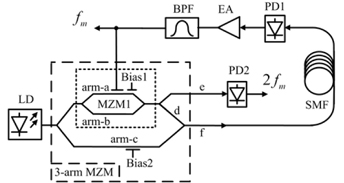
The structure of the three-arm MZM is composed of a phase-modulating arm-a, a non-modulating arm-b, and a bias arm-c constructed in parallel. The arm-a and arm-b connected with two Y branches operates as a two-arm MZM1. Output of the MZM1 is split where the upper output (port-e) is connected to PD2 and the lower output (arm-d) is combined with arm-c via another Y branch. If the MZM1 is biased at the maximum transmission point (MaxTP) where arm-a and arm-b are in phase, the doubled frequency of the modulation electrical signal on MZM1 is obtained at the output of the PD2. The port-f is the output for the oscillation signal of fundamental-frequency which is recycled to the electrical port of the three-arm MZM through a long optical fiber link, followed by an electrical amplifier and a fundamental-frequency selective filter. The operation principle can be studied firstly by considering a modulation signal
where
The photo-current generated by PD2 can be expressed as
where
where
where
III. EXPERIMENTAL AND DISCUSSION
Experiment based on the structure shown in Fig. 1 was conducted. The three-arm MZM was constructed by a single-arm-drive Z-cut MZM (Thorlabs LN58) serving as MZM1 and a phase modulator (Thorlabs LN53) as arm-c which were connected by three 3-dB polarization maintaining fiber couplers. The three-arm MZM was placed in a wooden box in order to isolate it from environmental interference. Both PD1 and PD2 (Optilab PD-30) have a -3 dB bandwidth of 28 GHz and a responsivity of 0.8 A/W. The microwave amplifier has a maximum gain of 50 dB. The bandpass filter with 9.5-GHz center frequency has a -3 dB bandwidth of 20 MHz. The length of the optical fiber is about 89 m corresponding to FSR of 2.3 MHz which can be seen in Fig. 3.
In the experiment, the MZM1 was carefully biased to MaxTP by manually adjusting the voltage at bias-1 to minimize the fundamental signal at the output of PD2. Thanks to the high stability of the commercial MZM1 used and the wooden box, the bias-1 can be held for a few hours. Nevertheless, a low-frequency pilot tone based feedback control should be applied to hold the MATP at bias-1 in real time [12]. The arm-c was held on quadrature with respect to the arm-a by a bias controller based on monitoring the average optical intensity at port-f. A fundamental microwave signal at 9.5 GHz and a frequency-doubled signal at 19GHz were generated at PD1 and PD2, respectively.
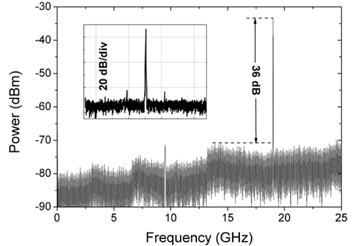
Figure 2 shows the RF spectrum of the frequencydoubled signal measured by an electrical spectrum analyzer (Agilent E4440A). It clearly shows a pure frequency-doubled signal at 19 GHz is obtained which is 36-dB greater than the fundamental-frequency component.
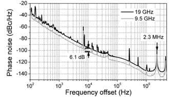
The phase noises of the fundamental and frequencydoubled signals shown in Fig. 3 were measured by using a signal source analyzer (Agilent 5052A) which covers a frequency range below 7 GHz. To measure the phase noise of the generated 9.5- and 19-GHz signals, the microwave signals were down-converted to an intermediate frequency by mixing with a reference signal which is generated by a signal generator (Agilent E8267D). As can be seen, the phase noises of 9.5- and 19-GHz signals are -96 dBc/Hz and -102.1 dBc/Hz respectively at 10 kHz frequency offset. The phase noises of the generated signals are 10-dB greater than those of the reference signals, ensuring reliable measurements of phase noise. The phase noise of the 19 GHz signal is approximately 6-dB greater than that of the 9.5 GHz signal, which agrees well with the theoretical prediction of 20log102 = 6 dB. Sidemodes of the OEO with constant frequency spacing of 2.3 MHz are observed and are lower than -100 dBc/Hz.
A frequency-doubling OEO has been proposed employing a three-arm MZM configured by utilizing a commercial single-arm-drive MZM and a phase modulator. Compared with previously reported frequency-doubling OEOs, the proposed system has two advantages: 1) there is no need to employ optical sideband modification devices in the loop; 2) the three-arm MZM which is the key element of the proposed system can be monolithically integrated to obtain high stability. The frequency-doubled signal at 19 GHz was obtained experimentally and was 36-dB greater than the fundamental-frequency signal.