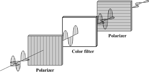
The contrast ratio (CR) is one of the critical characteristics of display applications. To achieve a high CR, it is important to reduce the light leakage in the black state and increase the transmittance in the white state. Light leakage in the black state of liquid crystal displays (LCDs) is caused by scattering media in the panels. In general, the polarization state of linearly polarized light by an input polarizer is broken slightly at the color filter with nanocomposite media, which can produce light scattering. Owing to partially depolarized light, the output polarizer crossed to the input polarizer cannot block the incident light perfectly. Hence, light leakage occurs, degrading the contrast ratio.
LCDs need to use color filters in each pixel to obtain the desired colors because they are not emissive type displays. On the other hand, most color filters contain nanoparticles that cause light scattering. Figure 1 presents a schematic diagram of the vector expression of the electric field, and light leakage caused by the scattering effect at the color filter when a color filter is sandwiched between two crossed polarizers [1-3]. The linearly polarized light is obtained after light passes through the input polarizer, and the oscillation direction of the light is parallel to the transmission axis of the polarizer. When this light meets the nanocomposites in the color filter, light scattering occurs and the polarization state is partially broken. This partially depolarized light becomes randomly polarized states. Of these states, the light component parallel to the transmission axis of the output polarizer escapes and becomes leakage.
In a more detailed description of the change in polarization, the cause of the polarization change is not for the retardation effects but for light scattering because the retardation value of the color filter is less than a few nm.
This study examined the size effect of a color filter nanocomposite on the contrast ratio in terms of the depolarization parameter.
To examine the scattering effect of nanoparticles in a medium related to depolarization, the size effect of the particle about scattering was analyzed by macroscopic fluctuation theory [4 - 6]. The total scattered power, P, is linearly proportional to the incident beam intensity I0 as
where the constant of proportionality is known as the scattering cross section [7]. The scattering cross section, σ, having the dimensions of area, can be interpreted as the effective geometrical area of the scatter for removing light from the incident intensity.
The optical field was assumed to be of the incident beam intensity I0 as
In response to the applied field, the scatter develops a dipole moment
where σ(ω) is the polarizability of the particle. As a consequence of the time-varying dipole moment given by Eq. (3), the particle will radiate. The intensity of radiation at a distance, L, from the scatterer is given by the magnitude of the Poynting vector as follows [7 8]:
A function of the pigment size on the cross-sectional area of scattering can be derived assuming that the scattering particles in the medium are a gathering of dielectric spheres. The dielectric constants of the dielectric sphere and medium are ε1 and ε, respectively. The radius of the dielectric spheres is
In addition, the cross-sectional area of scattering can be expressed as Eq. (6). The cross-sectional area of the scattering is proportional to the 6-power of the particle size [7].
Light leakage is closely related to depolarization. Therefore, the depolarization parameter (D.P.) was used to define the light leakage quantitatively. The depolarization parameter can be expressed as Eq. (7) [9].
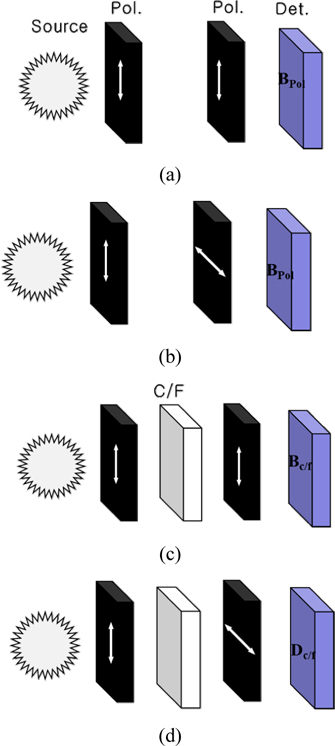
Figure 2 shows the measurement method of the depolarization parameter. The white state was used when the transmittance axes of the two polarizers are parallel to each other and the black state when the transmittance axes of the two polarizers are crossed.
If the light leakage under the crossed polarizers including the color filter is equal to that between the crossed polarizers without a color filter, the depolarization parameter becomes 1. On the other hand, if the depolarization parameter approaches 0, the light leakage under crossed polarizers including a color filter is increasing compared to the light leakage between crossed polarizers. Therefore, the depolarization parameter can be considered as a factor that represents the reduction ratio of the contrast due to light scattering by the color filter.
To measure the depolarization parameter with various pigments of the color filter materials, three types of samples were prepared for each red, green and blue pigment. ELS-8000 (OTSUKA) was used to measure the mean radius of the pigment by dynamic light scattering. Table 1 lists the measured mean diameters of the pigments.
[TABLE 1.] Measured average radius of various pigments for color filter materials
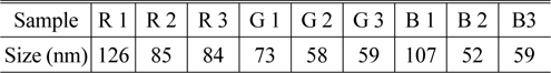
Measured average radius of various pigments for color filter materials
Various color filter samples made by the various nanosized pigments are located between two polarizers and the transmittance of the samples was measured with CT-1 (TSUBOSAKA) under crossed and parallel polarizers. The contrast ratios of the samples were calculated from measured transmittances, and are listed in Table 2. In two polarizers without a color filter, the contrast ratio was 100,200:1. The depolarization parameter of the samples, which is represented in Table 2, could then be obtained.

Measured contrast ratio and calculated depolarization parameters of the various color filter samples
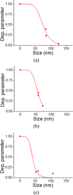
Table 2 also lists the depolarization parameters with various pigment sizes. When the pigment size was 0, which means no pigment, the depolarization parameter was 1. The depolarization parameter of the blue color filter with a size of 58 nm was lower than that of 59 nm. With the exception of this result, the depolarization parameter increased with decreasing pigment size. Therefore, the color filter with a small pigment size can reduce the light leakage caused by the light scattering in the color filter between two crossed polarizers.
From Eq. (2), the scattering cross section of the pigment particle is proportional to the sixth power of the radius. Therefore, the depolarization phenomenon of the pigment particles is proportion to the sixth power of the radius because the depolarization phenomenon is strongly related to the light scattering effects. Therefore, the depolarization parameter can be predicted to be inversely proportional to the sixth power. The depolarization parameter as a function of the size of the pigment particles can be estimated by a depolarization function (D. F.) using the following equation:
where x is the radius of the scattering particles, which means the particle size of the pigment in the color filter and xc is defined as the critical size. In Eq. (8), if the size of the scattering particle is larger or smaller than the critical size, the scattering effects are reduced symmetrically. When the size of the scattering particles is equal to that of the critical size, the depolarization parameter becomes 1/2. Near the critical size, the depolarization parameter is changed dramatically. This was attributed to the scattering effects reaching a relative maximum with the critical size, which is a similar phenomenon of the resonance in the frequency domain.
Using the depolarization function, the depolarization parameter was fitted as a function of the size of the scattering particle, as shown in Fig. 3. From curve fitting, the depolarization parameter began to change over the size of about 20 nm and it roughly saturated with the size of 100 nm. The resulting critical sizes for the red, green and blue color filter were 74 nm, 55 nm and 40 nm, respectively.
This shows that the critical size is approximately 0.1 times the wavelength of the transmitted light of each color filter.
Rayleigh scattering is mostly associated with light scattering by small particles, in which small refers to the size parameter x << 1, with x = 2πr/λ [10]. H. Moosmüller calculated various scattering effects as function of the particle size parameter. By the single scatter with refractive index of 1.55, Rayleigh scattering occurs when the size parameter is between 0.1 and 1.2. For the wavelength of 550 nm, the size parameter x can be converted into the particle size r, which is between 8.75 nm and 105 nm. This Rayleigh scattering regime agrees with our fitting function.
Consequently, to reduce the light leakage in liquid crystal displays, the size of the nano-particles in the color filter should be much smaller than the critical sizes for each wavelength. Such applications are expected to produce high quality LCDs with the optimal contrast ratio.
The contrast ratio is one of the most important characteristics of liquid crystal displays. The color filter in a liquid crystal panel is commonly used. When the color filter is located between two crossed polarizers, the size of the pigment can give rise to a decrease in the contrast ratio due to Rayleigh scattering at the nanoparticles in the filter. This study examined the size effect of the color filter pigment on the contrast ratio in terms of the depolarization parameter. The depolarization function, which is a useful function to predict the reduction of the contrast ratio of the color filter, was also proposed. As a result, to increase the contrast ratio in liquid crystal displays, the size of the nanoparticles in the color filter should be much smaller than the critical sizes for each wavelength.