The Internet of things (IoT) refers to the interconnection of services and technology used by all people, goods, and data to collect, share, and create information via the Internet. It will be applied to not only information and communication technology (ICT), but also to industry in general. It is therefore expected to solve the social problems and inconveniences of daily life. For this reason, the government has attracted attention to IoT as a growth engine for the next generation [1].
The services and technology of the IoT are in contact on a daily basis. Radio frequency identification (RFID) technology is the most widely used IoT technology and is compatible with various smart phones and forms of payment. RFID is used to identify objects from a distance of a few meters using a stationary reader to communicate wirelessly with small battery-free transponders (tags) attached to objects. It also provides two important basic functions for IoT: the identification and communication of RFID. It can be used to determine the approximate location of objects, thereby providing the position of the reader [2,3].
This paper proposes a small loop antenna for mobile UHF RFID devices. To reduce the antenna size, a ferrite sheet optimized for 900 MHz band is applied. The performance of the antenna is investigated by comparing it to that of an antenna without a ferrite sheet.
1. Ferrite Sheet Characteristics
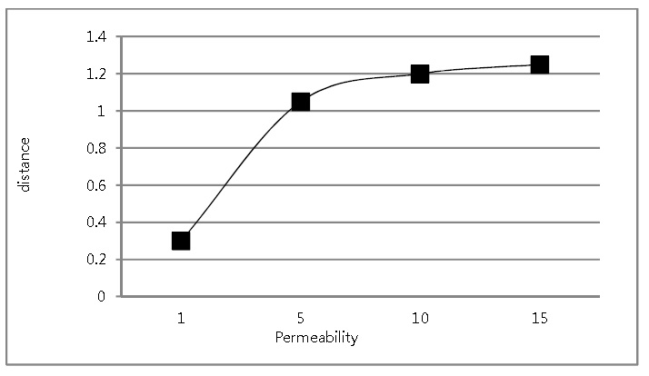
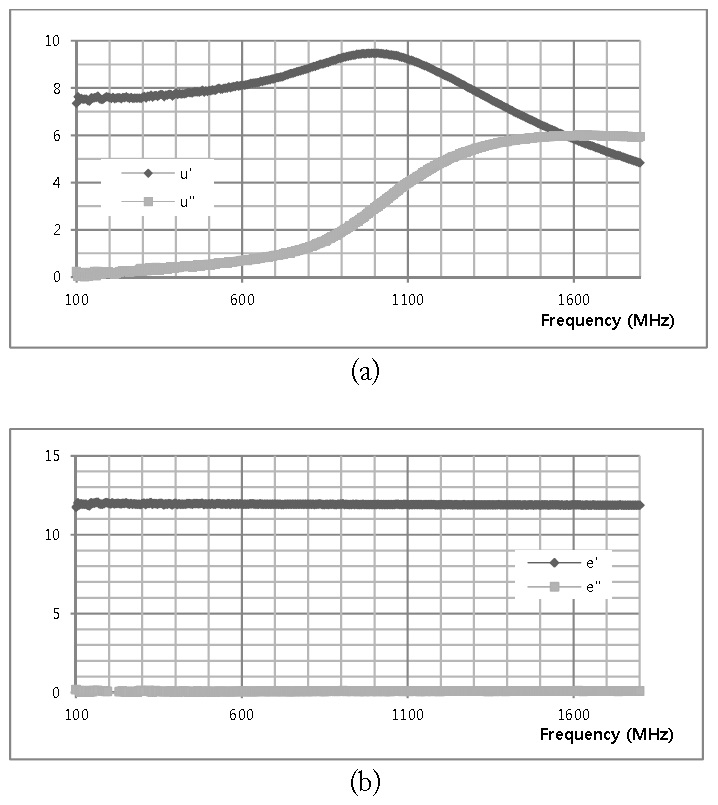
Ferrite sheets show high permeability and high permittivity. These characteristics are highly desirable for the miniaturization of many different RF/microwave devises, including antennas. In particular, the characteristic of high permeability is effective for increasing recognition distance by strengthening the flux density of the magnetic field on near-field communication antennas. To find the range of effective permeability on the UHF band, we simulated the recognition distance corresponding to the permeability, as shown in Fig. 1. Fig. 1 shows an inductive coupling simulation result with both a manufactured antenna and a standard antenna. Each of the antennas is made of magnetic permeability. In terms of permeability, the same frequency is represented while maintaining distance. With high permeability, distance characteristics appear further away. As the permeability becomes higher, the recognition distance becomes enlarged. However, if the permeability is greater than 8, it can be confirmed that the increased rate of recognition distance is reduced. Thus, the optimal range of permeability is from 8 to 10. Conventional ferrite sheets on the HF band are made of the spinel type cobalt ferrite. In this paper, due to the characteristics of low magnetic loss and higher permeability on the UHF band, hexagonal barium ferrite (Ba-ferrite) was used, and the ferrite sheet was annealed at 800℃–900℃. The constitutive parameters of ferrite sheet are shown in Fig. 2. It has a complex relative permeability of 9.29+
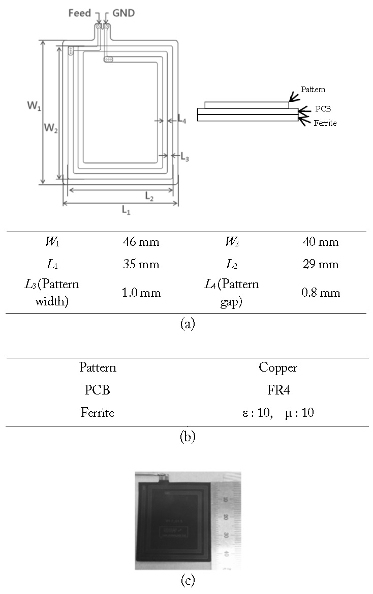
Fig. 3 shows the configuration of the proposed antenna. The proposed antenna consists of a loop and a ferrite sheet. The loop antenna is fabricated on a flexible printed circuit board (PCB) with a thickness of 0.08 mm. The performance of a loop antenna is designed by considering that the antenna is attached on a ferrite sheet with a thickness of 0.16 mm. The dimension is 46 mm×35 mm×0.24 mm. The proposed antenna is optimized using the CST Microwave Studio (CST MSW; Computer Simulation Technology AG., Darmstadt, Germany)—3D EM simulator. The optimal design parameters for the proposed antenna are shown in Fig. 3.
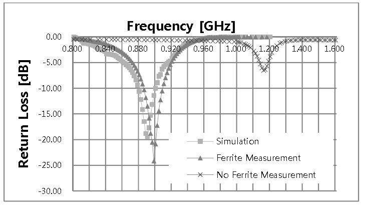
Fig. 4 shows the simulated and measured return loss characteristics of the proposed antenna. The measured result agreed with the simulated one. From the measurement, the 6 dB return loss bandwidth was 45 MHz (5%) ranging from 880 to 925 MHz, which is wide enough to cover the entire EPC UHF band (902–928 MHz).
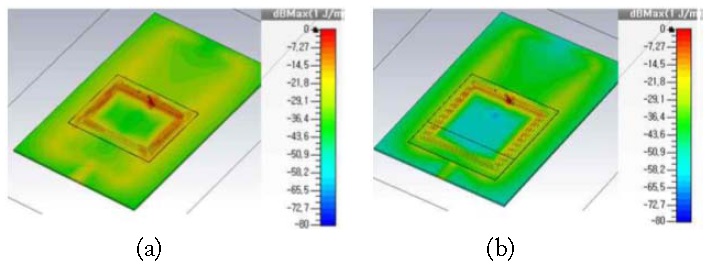
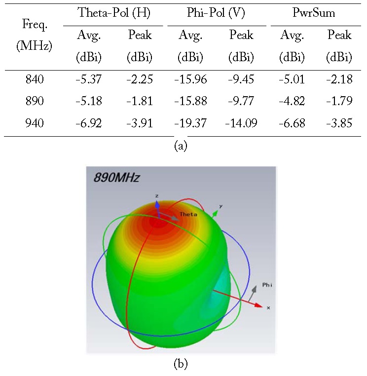
To evaluate the performances of the proposed antenna, a rectangular loop without a ferrite sheet is optimized on the same resonance frequency. The size of the proposed antenna is about 70% of that of the compared antenna. The permeability widens the antenna bandwidth. The permittivity reduces the antenna size but narrows the antenna bandwidth. Thus, both permeability and permittivity reduce antenna size without narrowing the bandwidth. Fig. 5 depicts the simulated magnetic energy distributions on each rectangular loop antenna at 900 MHz. One can clearly see that the proposed antenna has enhanced magnetic energy density in spite of its small size. Fig. 6(a) and (b) shows the measured antenna gain. We can see that at 900 MHz (840–940 MHz), the antenna has an average gain of about -5 dBi.
A small loop antenna for mobile UHF RFID devices is proposed. By applying a ferrite sheet optimized for a 900 MHz band, the size of the antenna is reduced to about 70% of that of a conventional rectangular loop. In spite of its small size, it has a bandwidth of 45 MHz for a return loss less than -6 dB and yields superior magnetic energy density. The proposed antenna is sufficient to cover both near and far field UHF EPC global frequency band communications (902–928 MHz).