Since the successful launch of Korea Space Launch Vehicle–I (KSLV–I) on Jan. 30, 2013, Korea’s Space Program has gained momentum. According to Vision 2040, which was announced recently by Korea’s Space Program, the launch of Korea’s first lunar orbiter and lander is planned by 2020 and a lunar sample return mission is planned by 2025. In addition, a Mars orbiter mission as well as a landing mission is planned by the end of 2030. Furthermore, other deep space missions including asteroid and comet explorations are also planned by the end of 2040. In keeping with this plan, the Korean Astronautical Society has extended its interest to the lunar mission, and numerous related basic studies have been widely performed. Korea Aerospace Research Institute (KARI) is also performing prephase development and research for the lunar mission, which will be ready to launched in the next decade.
For trajectory design point of views, Song et al. (2008) developed the lunar mission design software, and designed an optimal Earth-Moon transfer trajectory using direct departure from circular initial Earth parking orbit with impulsive high thrust. Later, Song et al. (2009c) presented various optimal Earth- Moon transfer trajectories using intermediate Earth departing loop orbits by upgrading the previously developed software. An Earth-Moon transfer trajectory design considering the spacecraft’s visibility from Daejeon ground station was also conducted by Woo et al. (2010). With low thrust concepts, Lee & Bang (2007) derived optimal low thrust trajectory solutions with simplified 2-dimensional flight dynamics. Later, Song et al. (2009a) presented optimal Earth-Moon transfer trajectories using both the constant and variable low thrust with the 3-dimensional problem and with 3rd body perturbations.
In addition, a lunar cargo mission design strategy using variable low thrust by combining both the analytical and numerical optimization method was presented by Song et al. (2009b). Through the use of finite thrust concepts, Song et al. (2010a) presented design results with Trans Lunar Injection (TLI) maneuver using finite thrust. Also, Song et al. (2011) performed analysis on delta-V losses during lunar capture sequence using finite thrust with various on- board thrusters’ performances. Cho et al. (2010) presented a Trajectory Correction Maneuver for lunar mission trajectory based on 3-body dynamics, and No & Jeon (2010) performed an Earth-Moon transfer trajectory design by mixed impulsive and continuous thrust as other design studies to prepare for Korea’s future lunar mission. To design missions with a spacecraft located in very close proximity to the Moon, Cho et al. (2009) analyzed optimal lunar landing trajectories with knowledge of parking orbits before the descent phase with assumptions of 2-dimensional problem and later, Jeong et al. (2010) presented a precise planetary landing method with terrain aided inertial navigation. In subsequent research, Song et al. (2010b) developed a precise lunar orbit propagator and analyzed the lunar polar orbiter’s lifetime, concluding that the lunar polar orbiter’s lifetime is strongly affected by the Moon’s non-spherical gravitation and the Earth’s point mass perturbation. In addition to these studies, Rew et al. (2010) presented conceptual design results for KARI’s dynamic simulator, which is especially designed to prepare Korea’s future lunar explorer. In addition to these trajectory design studies, several preliminary design studies have been performed to consider deep space communication. Performance analysis of downlink for the lunar exploration was done by Lee et al. (2010), who first designed and analyzed the downlink performance of a data link between a lunar orbiter and an Earth station. Later, they suggested modulation and channel coding schemes to meet the link margins for lunar explorer (Lee et al. 2011). Also, Kim et al. (2010) presented the concept of a Korean Deep Space Network (DSN) with link margin and suggested other technical requirements for successful Korean DSN development.
Although numerous pre-design studies were performed as discussed above, more detailed contact analysis studies for the lunar orbiter mission are still required, as these pre-design studies were only focused on how to fly to the Moon or the links margins would be. Actually, works done by Woo et al. (2010) already adapted the concept of the lunar explorer’s visibility conditions, and analyzed visibility conditions from the Daejeon station at both the TLI and Lunar Orbit Insertion (LOI) maneuvers to design an Earth- Moon transfer trajectory. However, Woo et al. (2010) conducted their analysis by only considering cut-off angle constraints as the major condition to secure the orbiter’s contact opportunities, which are not sufficient for the spacecraft when it is orbiting around the Moon. Therefore, the main goal of this research is to provide more detailed contact availability analysis, especially for the lunar orbiter. Detailed contact availability from given sites is basically derived based on geometrical relations between the typical ground stations at the Earth, the relative positions of the Earth and Moon, and finally the lunar orbiter itself. Also, both the cut-off angle and the orbiter’s Line of Sight (LOS) conditions, whether the orbiter is located at near or far side of the Moon seen from the Earth, are considered to determine the ground contact opportunities. Based on these conditions, the characteristics of ranging and tracking parameters (range, azimuth, elevation and their associated rates) are also derived and analyzed in detail.
In Section 2, ground contact geometry for the lunar orbiter is discussed with two necessary constraints (both cut-off angle and LOS) to secure full contact with the orbiter. Section 3 provides presumptions that are made to simulate the given fictitious lunar orbiter mission with selected candidate ground sites’ information. The results of the analysis are presented in Section 4, including results for the Daejeon site alone as well as results for the world-wide separated networks. Finally, in Section 5, conclusions are made. With the results provided in this research, it is expected that further progress will be made both in Korea’s lunar orbiter trajectory design and in the communication link analysis studies.
2. GROUND CONTACT GEOMETY FOR THE LUNAR ORBITER
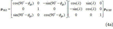
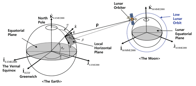
The first condition to determine the contact opportunity of the lunar orbiter from a given site is to find out whether it is located above the horizon. This could be achieved by determining the slant-range vector from the site to the orbiter. As the lunar orbiter’s states are expressed in the Moon-centered Moon Mean Equator and IAU vector of epoch J2000 (M-MME2000) coordinate system, several coordinate transformations are needed to find the orbiter’s slant-range vector expressed in topocentrichorizon frame. The International Astronomical Union/International Association of Geodesy (IAU/IAG) defined the M-MME2000 system as completed with the Moon as the reference body, the Moon’s mean equator as the reference plane and the reference direction as the IAU vector (Seidelmann et al. 2007). The lunar orbiter’s states expressed in the Earth-centered Earth Mean Equator and equinox of epoch J2000 (E-EME2000) coordinate frame, can be obtained states expressed in M-MME2000 coordinate frame, with Eq. (1).

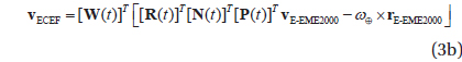
where is the DCM(Direction Cosine Matrix) to convert both the reference plane (from the Moon’s mean equator to the Earth’s mean equator) and the reference direction (from the IAU vector to the vernal equinox direction). Also, is the simple manipulation matrix to convert the reference body from the Moon to the Earth. The formulation procedure of is well described in the literature by Seidelmann et al. (2007), and can be easily formulated using the Moon’s ephemeris expressed in E-EME2000 coordinate frame. More detailed definitions and their formulations for the Moon-centered coordinate system can be found in the literature by Song et al. (2010b). The transformations of the position and velocity vectors into range, azimuth, elevation and their associated rates in topocentric-horizon frame begins by converting the position and velocity vectors to Earth Centered Earth Fixed (ECEF) frame. Then, the slant-range, , and its rate, , vector from the site to the orbiter in ECEF frame can be found by Eq. (2) (Vallado 2007).


where is the orbiter’s position vector, is the velocity vector and is the given ground site’s position vector, all expressed in ECEF frame, respectively. can be derived when given the site’s geodetic latitude,

where and P(
The slant-range and its rate shown in Eq. (2) are based on the ECEF system, and thus, to determine azimuth (

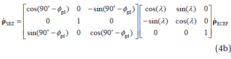
In Eq. (4),


Finally, the first condition to determine the contact opportunity of the lunar orbiter from a given site, whether it is located above or below the horizon, could be determined with simple conditions: if
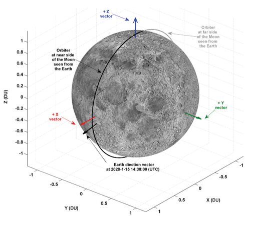
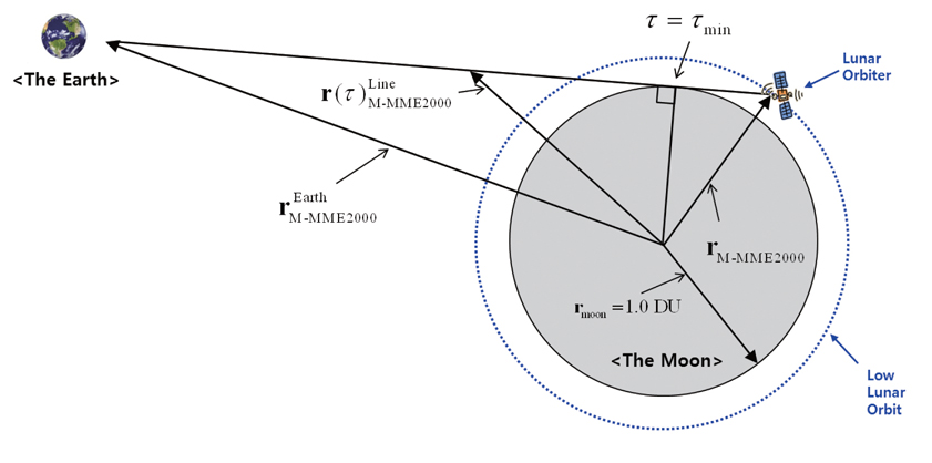
The second condition that must be checked to secure the lunar orbiter’s contact opportunity is the LOS conditions between the orbiter and the Earth. In Fig. 2, the LOS geometry for the lunar orbiter is shown. The Distance Unit (DU) shown in Fig. 2 is about 1738.2 km.
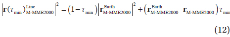
Suppose that the arbitrary Earth position vector expressed in M-MME2000 frame, , and the orbiter’s position vector in M-MME2000, , are known. A parametric representation of a line between two position vectors, , can then be expressed as (Vallado 2007):

where varies 0.0 ( ) to 1.0 ( ). If the values of τ which minimize the distance to the central body (in this case the Moon) are found, then the LOS conditions can be determined. To find the squared magnitude of firstly let both of the vectors, and , be as follows:


Then, the squared magnitude of can be found as:

Take the derivatives of Eq. (10) with respect to
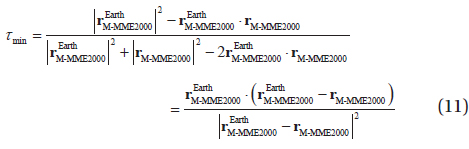
Squaring the norm of Eq. (7) and expand derived equations with separating terms to substitute

To determine LOS conditions, the first job is to determine
3. PRESUMPTIONS FOR FICTITIOUS MISSION
3.1 Lunar mapping orbit and numerical implications
To simulate ground contact opportunity for the fictitious low lunar orbiter, it is assumed that the orbiter is already inserted into the mapping orbit. The mapping orbit is assumed to be a circular lunar polar orbit, having 100 km altitude and 90 deg inclination, in reference to the M-MME2000 coordinate system at the epoch of 2020-01-01 00:00:00 (UTC). With given orbital conditions, the initial states of the orbiter in the inertial frame of the Moon, the M-MME2000 system, are given as about 1,837.400 km for X position component (X), about 1,633.505 km/s for z velocity component (Vz), while other state components (Y), (Z), (Vx), and (Vy) are all zeros. With the initial states as discussed, orbiter’s states are propagated and predicted for about 27.3 days, which is the Moon’s approximate orbital revolution period around the Earth. As the mapping orbit has a period of 118 min itself, the lunar orbiter will orbit the Moon about 334 times during the 27.3 days of propagation. Also, it is obvious that the typical ground stations located at the Earth will revisit their original locations just slightly more than 27 times during this period. In following discussions, it should be noted that all time units are based on the Earth’s time.
To predict the orbiter's states expressed in both Moon and Earth centered coordinate systems, a previously developed and performance verified precise lunar orbit propagator developed by Song et al. (2010b) is used and modified. This propagator was developed to design and analyze the spacecraft’s states flying in the vicinity of the Moon. However, of the various Earth centered reference frames the precise lunar orbit propagator developed by Song et al. (2010b) was only able to express the orbiter’s states in E-EME2000 coordinate system. For the purpose of this research, additional functionalities to express the spacecraft’s states in other Earth centered reference frames are implemented. To express the orbiter’s states in the topocentric horizontal coordinate system, the Earth-Centered, Earth-Fixed (ECEF) coordinate system is additionally implemented after conversion of the EME2000 system to Mean of Date (MOD) then to True of Date (TOD) system, which are done by applying the Earth’s precession and nutation angles and their rates. However, the ECEF system used in this research is actually a Pseudo ECEF system, as the pole wander angle could not be obtained from the Earth Orientation Parameters (EOP) table since our simulation dates are assumed to be in the year 2020. For the perturbing forces during simulations, accelerations due to the point masses of the Earth, Moon, and Sun are considered. Also, to compute acceleration due to the nonspherical gravitation of the Moon, fiftieth degrees and orders (50 × 50) of the LP165P model are considered. Consideration of 50 × 50 degrees and orders of the non-spherical gravitation of the Moon was due to the fact that it was found to be a least requirement to precisely analyze the orbits with altitudes in the range of 30-100 km at the Moon (Roncoli 2005, Song et al. 2010b). As for integration, the Runge-Kutta 7-8th variable step size integrator is used with truncation error tolerance of
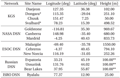
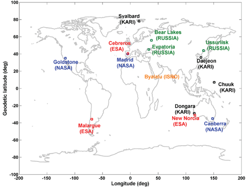
For candidate ground sites, four different (Daejeon, Dongara, Chuuk and Svalbard) KOMPSAT Ground Stations (KGSs) are considered for Korea’s future candidate ground sites. This means that these four KGSs could be part of Near Earth Networks (NENs) to support Korea’s future lunar missions. Among KGSs, note that the Dongara and Svalbard are commercially contracted sites. In additions to these KGSs, world-wide separated DSNs are also assumed as supporting sites for Korea’s lunar orbiter mission via international collaborations. For world-wide DSNs, ten different sites are selected as candidates, including NASA’s three DSN sites Goldstone, Canberra and Madrid (JPL 2013), three Russian sites Evpatoria, Ussuriisk, and Bear Lakes (Altunin 1993), ESOC’s three sites Malargüe, Cebreros and New Norcia (ESA 2013) and one ISRO site Byalalu (ISRO 2013). In Table 1, geodetic locations and heights of selected candidate sites are shown, and their world locations are also plotted in Fig. 3.
[Table 1.] The geographical locations for candidate sites, both the KGSs and DSNs.

The geographical locations for candidate sites, both the KGSs and DSNs.
4.1 Contact analysis for the Daejeon site
4.1.1 Results with no constraints
As for the first simulation result, the fictitious lunar orbiter’s contact opportunities from four different ground sites (Daejeon, Dongara, Chuuk and Svalbard) are treated. For given typical ground stations, the characteristics of ranging and tracking parameters (range, azimuth, elevation and their associated rates) are also derived and analyzed. In Section 2, two major constraints to secure the lunar orbiter’s contact opportunity from the given typical Earth ground station are already discussed. However, in this subsection, the contact opportunities are first analyzed without any constraints to see how these constraints will finally affect the orbiter’s overall contact opportunities.
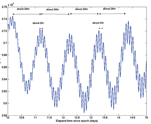
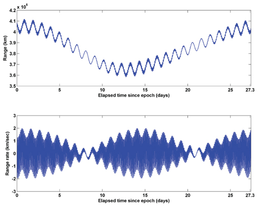
In Fig. 4, the orbiter’s range (top) and its rate (bottom) profile observed from the Daejeon site are shown during 27.3 days of prediction. At the top of Fig. 4, it can be easily noticed that ranging profile from the Daejeon site has the tendencies of short, mid and long-term periodic sinusoidal variations. Ranging profile from the Daejeon station have minimum range variations from about 358,397 km to the maximum of about 411,803 km for long-term periodic sinusoidal variations with about 27.3 days of periodicity. For mid-term variation, it has about 24 hours of periodicity, and for short-term variations, it has about 2 hours of periodicity. These phenomena are due to the simultaneous motions: the Moon's revolution around the Earth has about 27.3 days of periodicity, the Earth's rotation itself has about 24 hours of periodicity, and finally, the orbiter’s orbiting around the Moon is given to have about 2 hours of periodicity. For the range rates seen from the Daejeon station, which are shown at the bottom of Fig. 4, the maximum range rate is found to be about 2.000 km/sec, and the minimum range rate is found to be about -1.986 km/sec. In Fig. 4, it can also be easily noticed that the amplitude of both range and rate variations, especially the short-term variation, are dramatically decreased near about from 6.70 to 9.61 days and from about 19.84 to 22.32 days after the orbit epoch. This indicates that the relative geometry between the orbiter and the Daejeon station is somewhat changed to reduce the amplitude of variations. Fig. 5 shows a zoomed-in view of range profile, again observed from the Daejeon site, during the intervals from 10 to 15 days of elapsed time since the epoch. It can be clearly seen from Fig. 5 that the mid-term and short-term sinusoidal variation is directly related to the fact of the Earth's rotation itself and the orbiter’s orbiting around the Moon, respectively.
4.1.2 Results with considering both the horizontal and LOS constraints
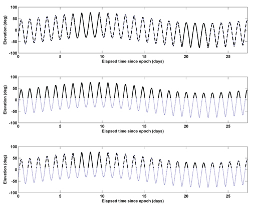
In this subsection, the fictitious lunar orbiter’s contact opportunities are derived and analyzed considering both the horizontal and LOS constraints. In Fig. 6, the lunar orbiter’s elevation angle variation profile observed from the Daejeon site during 27.3 days of prediction time is shown with two major constraints, as discussed.
In the top of Fig. 6, orbiter’s elevation profile seen from the Daejeon station only with LOS constraint is shown. Here, the solid-bold line indicates the elevation angle profile at times when the orbiter is located at the near side of the Moon seen from the Earth. The dotted line indicates the elevation angle profile when the orbiter is located at the far side of the Moon. For this simulation case, the orbiter is located at the near side of the Moon about 266 times during the 27.3 days of prediction time. The minimum duration of when the orbiter is located at near side of the Moon is found to be about 69.00 min, while the maximum duration is found to be about 4,173.00 min (about 2.90 days). Also, the mean duration is found to be about 106.55 min. It is discovered that the orbiter’s near side staying duration is changed according to the geometry between the mapping orbit’s orbital momentum vector and the Earth direction vector at the given instant of time. Details of this discovery will be discussed shortly. When regarding LOS condition as the only constraint to analyze orbiter’s contact opportunities, it is found that orbiter is located at the near side of the Moon for about 19.68 days, which is about 72.09% of 27.3 days. In the middle of Fig. 6, orbiter’s elevation profile seen from the Daejeon station only with horizontal constraint is shown with a masking angle condition of 8 degs. The solid-bolded line in the middle of Fig. 6 indicates the cases when the orbiter is located above the horizontal plane, and the dotted line is for when the orbiter is located below the horizontal plane. When horizontal condition is the only constraint considered to analyze orbiter’s contact opportunity, it is found that orbiter is located above the horizontal plane about 26 times during 27.3 days. Also, the maximum duration for which the orbiter is located above the horizontal plane was found to be about 13.32 hours, and the minimum duration was found to be about 8.10 hours with mean duration of 10.74 hours. For this simulation case, the orbiter is located above the horizontal plane of the Daejeon station about 11.68 days out of 27.3 days, which is about 42.79%.
At the bottom of Fig. 6, the orbiter’s elevation profile is shown with both the LOS and horizontal constraints applied. The solid-bolded line in the bottom of Fig. 6 indicates the cases when contact between the lunar orbiter and the Daejeon station is truly made, meaning that the both LOS and horizontal constraint conditions are satisfied. In contrast, the dotted line indicates cases when contact is completely lost. Hereinafter, the expression “true contact” will be used to reflect the simulation cases with both constraints applied. It is found that the orbiter is able to contact the Daejeon station about 138 times during the 27.3 days of prediction time span with mean duration of about 89.20 min. Also, the maximum duration of true contact is found to be about 13.28 hours, and the minimum duration is found to be about 1 min. At the moment of 2020-1-11 9:52:00 (UTC), the minimum duration of true contact with the orbiter occurred due to the dramatic combination of applied two constraints. At this instant, the orbiter’s elevation angle seen from the Daejeon station is found to be about 8.02 deg (the orbiter was just rising as seen from the Daejeon station) with azimuth angle of 68.61 deg. However, coincidentally, the lunar orbiter was just about to hide behind the Moon as seen from the Daejeon station which means that LOS condition was not satisfied at that moment. These phenomena were occasionally observed during 27.3 days of prediction, and were found to be the major reasons affecting the orbiter’s true contact durations. About 4 through 7 times of true contact will be made during the orbiter’s one orbit pass, except for the cases when the entire one orbit pass is accessible. Here, one orbit pass is defined as when the orbiter is located above the horizontal plane seen from the Daejeon station. If both constraints are applied, total duration of possible contact with the Daejeon station is found to be about 8.55 days, which is only about 31.32% of 27.3 days.
As already discussed, the lunar orbiter’s near side duration seen from the Earth station is closely related to the geometry between the mapping orbit’s orbital momentum vector (+Y axis vector for this simulation case as the lunar mapping orbit is assumed to be 90 deg inclined orbit) and the Earth direction vector at given instant of time. If the orbital momentum vector and the Earth direction vector are nearly perpendicular, this duration will be minimized. Otherwise, if the orbital momentum vector and the Earth direction vectors are nearly parallel, either same or opposite direction, the durations will be maximized. Actually, starting from 2020-1-15 14:38:00 (UTC) and continuing to 2020-1-15 16:35:00 (UTC), it is found that the orbiter is located at near side and this near side duration (about 69.00 min) is found to be the minimum during the entire prediction time span. Fig. 7 depicts this situation and plotted with about 118 min (the mapping orbit’s orbital period) of propagation from 2020-1-15 14:38:00 (UTC) to include the far side orbit. In Fig. 7, DU is used to scale the coordinate axes, which is about 1,738.2 km. It can be easily observed in Fig. 7 that the orbital momentum vector (+Y axis vector) and the Earth direction vectors are nearly perpendicular.
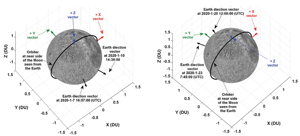
Some curiosity might occur about the phenomenon just observed, the maximum duration near side case, found to be about 4,173.00 min (about 2.90 days). This result indicates that the orbiter always remains at near side of the Moon seen from the Earth during about 2.90 days. Actually, starting from 2020-1-7 16:57:00 (UTC) and continuing to 2020-1-10 14:38:00 (UTC), it is found that the orbiter always remains at near side of the Moon, which is the maximum duration at near side. During the prediction time span of 27.3 days, another similar case is observed. Starting from 2020-1-20 12:00:00 (UTC) and continuing to 2020-1-23 7:45:00 (UTC), the orbiter again remained at near side of the Moon for about 4,058 min (about 2.82 days). The orbiter’s cases of staying for a longer time at near side of the Moon are found to have about 13 days of periodicity. The main reason for these phenomena are due to the Moon’s revolution around the Earth, which is changing the vector geometry between the orbital momentum vector (+Y axis vector) and the Earth direction vector regularly. Changes in these relative vector geometries also reduced the shortterm range variation’s amplitude, as already discussed and shown through Fig. 4. In Fig. 8, vector geometries for the orbiter when it remained at near side of the Moon for longer times are shown. Left side of Fig. 8 is for the maximum duration (2.90 days) near side case, and right side of Fig. 8 is for another (2.82 days) discovered near side case. Fig. 8 is plotted with about 2.90 days and 2.82 days of orbit propagation starting from 2020-1-7 16:57:00 (UTC) and 2020-1-20 12:00:00 (UTC), respectively. DU (about 1,738 km) is again used to scale the coordinate axes. In Fig. 8, it can be clearly seen that the orbiter is always located at near side of the Moon seen from the Earth when the Earth direction vector and the orbital momentum vector (+Y axis vector) are pointing either in nearly the same direction or the opposite direction. If the lunar landing mission is planned, scheduling a descent trajectory in this time zone (maximum duration near side case) would provide more opportunities to continuously track the lunar lander. However, note that the time zone of the maximum duration near side case may be seriously affected by the lunar mapping orbit’s shape.
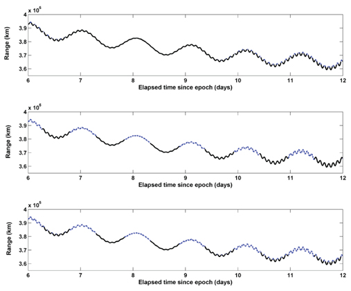
In Fig. 9, the lunar orbiter’s range variation profile observed from the Daejeon site during the intervals of 6 through 12 days since the epoch is shown. Just as in Fig. 6, the orbiter’s contact opportunities are expressed with solid-bolded or dotted lines when only LOS constraint (in the top of Fig. 9), only horizontal constraint (in the middle of Fig. 9) and when both LOS and horizontal constraints (in the bottom of Fig. 9) are applied. From Fig. 9, the effect of applying both the LOS and horizontal constraints while analyzing orbiter’s contact opportunities can be seen more clearly. In addition, the amplitude decrease of the shortterm range variation near around 6.70 to 9.61 days after elapsed time of the orbit epoch is clearly shown. This amplitude decreasing time exactly matches the times when maximum duration near side occurred.
4.2 Contact analysis with world-wide networks
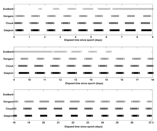
As was previously stated in Section 3, four different (Daejeon, Dongara, Chuuk and Svalbard) KGSs are considered for Korea’s future candidate ground sites to support lunar missions, meaning that these four KGSs could be Korea’s future NENs. In Fig. 10, the orbiter’s contact availability is shown for each KGS during 27.3 days of prediction time. In Fig. 10, x-axis denotes the site’s name and y-axis denotes the time elapsed since orbit epoch in days. When the lunar orbiter is available to contact the given sites, available time is marked with a “square” symbol. In Fig. 10, it can easily be noticed that the Daejeon, Chuuk, and Dongara stations have almost equal available contact opportunities, as their longitudinal locations are nearly equal. However, for the Svalbard station, the first contact is made about 1.6 days after the epoch, and final contact about 15.4 days after the epoch. Later on, the Svalbard station was not able to make more contact with the orbiter during 27.3 days of prediction. These phenomena are closely related to the elevation angle variation profile of the orbiter, seen from the given sites. And the elevation angle variation profile is again directly related to the latitude of the given site, rather than the longitudinal location. Here, keep in mind that if the Earth ground track of the lunar orbiter is plotted, its latitudinal locations will always vary within a range of about ±29 degs. As shown in Fig. 10, the suggested four sites cannot provide continuous tracking of the lunar orbiter, which means that the international collaboration is necessary to track the future Korea’s lunar orbiter effectively. In Table 2, the orbiter’s major contact parameters are summarized for the given four KGSs when both the horizontal and LOS conditions are applied to secure the contact opportunity. Among the four sites, the Daejeon, Dongara and the Chuuk site have almost equal contacts rates; near about 32%. However, the Svalbard sites are found to have about 26.60%. This result is due to the differences in the total number of contacts (around 140 times for the Daejeon, Dongara and the Chuuk site, about 87 times for the Svalbard site), which is significantly affected by each site’s locations, in terms of both the longitude and latitude. For the Svalbard site, an interesting fact is that it was discovered that the maximum true contact duration (4,173 min) is equal to the maximum duration of near side case. This is due to the fact that during the entire time when the orbiter is located above the horizontal plane seen from the Svalbard site, the orbiter is also located completely at near side of the Moon seen from the Earth. For the minimum contact duration for the Svalbard site, it is given as 0.00 min, which actually means that it is less than 0.00 min, as the lunar orbiter’s ephemeris in this work is predicted in steps of 1 min intervals.
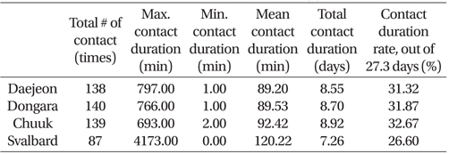
The summery of contact parameters for given four KGS sites when both the horizontal and LOS conditions are applied.
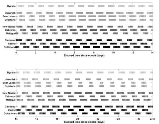
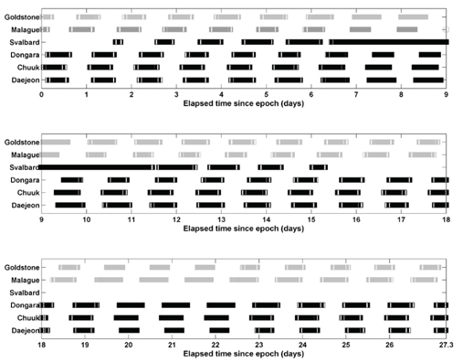
In this subsection, the orbiter’s contact availabilities for DSNs are investigated. For world-wide DSNs, ten different sites are selected as candidates, including NASA’s three DSN sites (Goldstone, Canberra, Madrid), three Russian sites (Evpatoria, Ussuriisk, Bear Lakes), ESOC’s three sites (Malargüe, Cebreros, New Norcia) and ISRO’s site (Byalalu). In Fig. 11, the orbiter’s contact availability is shown for each DSN during 27.3 days of prediction time. In Fig. 11, x-axis denotes sites name and y-axis denotes time elapsed since epoch of lunar orbiter in days. Again, as in Fig. 10, when the lunar orbiter is available to contact from given sites, it is marked with a “square” symbol. As shown in Fig. 11, NASA and ESOC’s three sites, uniformly distributed about 120 degs in longitude, can continuously contact without any contact losses during 27.3 days. However, the three Russian sites, as expected, cannot cover the entire predicted time span of 27.3 days, which is very similar to a phenomenon that was just discovered in the previous subsection for the Svalbard site case. If the primary ground site for Korea’s future lunar orbiter mission is located at the Daejeon site, a backup site for the Daejeon site could be NASA’s Canberra, ESA’s New Norica or Russia’s Ussuriisk site. However, the Russian Ussuriisk site would have slightly less contact availability than the Canberra and the New Norica sites. Also, as expected, KGSs located in this similar region, (i.e., the Chuuk and the Dongara site) showed similar contact availability. For other DSNs, ESA’s Cebreros and NASA’s Mardrid, NASA’s Goldstone and ESA’s Malargüe sites’ contact availability showed almost equal behavior, which means that they could be used as primary or backup sites for each other. If Korea is planning to construct a new ground site among Daejeon, Chuuk or Dongara to support the lunar or interplanetary missions, the best choice could be the Daejeon site, as most of the objects in the solar system lie within ±30 degs of latitude of the equator, including the Moon. Therefore, most of the DSNs are located just around ±30 degs of latitude in order to cover every mission effectively as well as to minimize antennas’ movement in declination. If the Daejeon site is selected as the one primary site out of three sites, the other two sites to support Korea’s mission, ESA’s Cebreros or NASA’s Mardrid, and NASA’s Goldstone or ESA’s Malargüe sites could be the best choices for international collaborations. This combination could enable continuous contact with the lunar orbiter without any contact losses. In Table 3, the orbiter’s contact parameters are summarized for the given ten DSN sites, when both the horizontal and LOS conditions are applied to secure the contact availability. With the exception of Russia’s Bear Lakes and Evpatoria sites (about 27.62% for Bear Lakes and 29.89% for Evpatoria) total contact duration rate with the orbiter for all sites was more than 30%. Although Russia’s Bear Lakes site showed the least coverage characteristics among other DSN sites, it still shows better performance than the Svalbard (26.60%) site, as shown in Subsection 4.2.1 However, it should be noted that if the spacecraft is on its way to the Moon or to other target planets, these sites would be helpful during the early Earth departure phase, where the contact availability is strongly dependent on the transfer orbit’s inclinations.
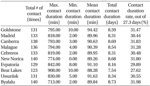
The summery of contact parameters for given ten DSN sites, when both the horizontal and LOS conditions are applied.
As was already discussed in Subsection 4.2.1, the four KGSs assumed in this research cannot provide continuous tracking of the lunar orbiter. Therefore, additional simulation was performed to select the best site location to compensate for this lack of contact opportunity. In Fig. 12, the compensated contact availability for four KGSs with two DSNs (Malague and Goldstone site) is shown. As shown in Fig. 12, Malague and Goldstone site show little difference in their contact coverage time zone, and it seems that Malague site is more appropriate than Goldstone site to collaborate with KGSs. Also, if one these two sites are selected as collaborating sites, Svalbard site has no more significant contributions while tracking the lunar orbiter when it is already inserted into the lunar mapping phase.
In this work, ground contact opportunity for the fictitious low lunar orbiter is analyzed. To determine the ground contact opportunities, both the cut-off angle constraints and the orbiter’s LOS conditions (weather orbiter is located at near or far side of the Moon seen from the Earth) are considered. Based on these conditions, characteristics of ranging and tracking parameters (range, azimuth, elevation and their associated rates) are also derived and analyzed for given typical ground stations; four KGSs for Korea’s future NENs and ten DSNs to support Korea’s future lunar orbiter mission. As a result, it was discovered that ranging profile for the lunar orbiter from the Earth ground site has short, mid and long-term periodic sinusoidal variations. For the fictitious lunar orbiter’s contact opportunities, it is discovered that the orbiter will continuously remain at the near side of the Moon for about 2.9 days, and this phenomenon happens twice per one lunar revolution around the Earth (about 27.3 days). Scheduling lunar descent or ascent trajectory in these time zones would provide more opportunities to continuously track the lunar lander. When both horizontal and LOS constraints are considered, the total duration of possible contact with the Daejeon station was found to be about 8.55 days, which is only about 31.32%, out of the 27.3 days of prediction time span. In additions, about 4 through 7 times of true contact will be made during one orbit pass of the orbiter seen from the Daejeon site. For the results with world-wide networks, if four different (Daejeon, Dongara, Chuuk and Svalbard) KGSs are considered as to be the future Korea’s candidate sites to support lunar missions, these four sites cannot provide continuous tracking of the lunar orbiter without the help of other DSNs. Considering the need to support not only the lunar but also other interplanetary missions to be performed in the future, the best option could be locate one site at Daejeon province, and utilize two other sites (ESA’s Cebreros or NASA’s Madrrid, NASA’s Goldstone or ESA’s Malargüe) to support Korea’s lunar or interplanetary mission via international collaboration. Although this research only dealt with the spacecraft in the lunar mapping phase, upcoming research will cover contact opportunities, including the lunar transfer phase as well as the capturing phase with a variety of lunar transfer scenarios.