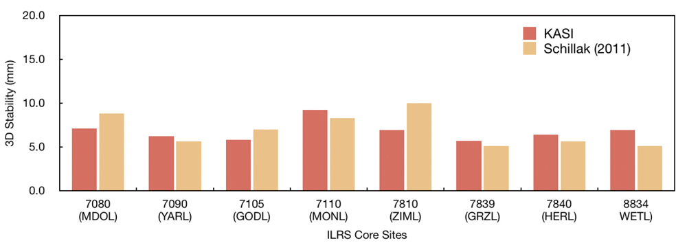
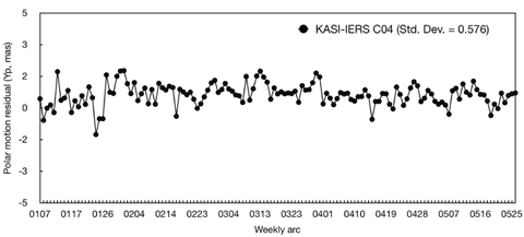
In this study, we present results of precise orbital geodetic parameter estimation using satellite laser ranging (SLR) observations for the International Laser Ranging Service (ILRS) associate analysis center (AAC). Using normal point observations of LAGEOS-1, LAGEOS-2, ETALON-1, and ETALON-2 in SLR consolidated laser ranging data format, the NASA/GSFC GEODYN II and SOLVE software programs were utilized for precise orbit determination (POD) and finding solutions of a terrestrial reference frame (TRF) and Earth orientation parameters (EOPs). For POD, a weekly-based orbit determination strategy was employed to process SLR observations taken from 20 weeks in 2013. For solutions of TRF and EOPs, loosely constrained scheme was used to integrate POD results of four geodetic SLR satellites. The coordinates of 11 ILRS core sites were determined and daily polar motion and polar motion rates were estimated. The root mean square (RMS) value of post-fit residuals was used for orbit quality assessment, and both the stability of TRF and the precision of EOPs by external comparison were analyzed for verification of our solutions. Results of post-fit residuals show that the RMS of the orbits of LAGEOS-1 and LAGEOS-2 are 1.20 and 1.12 cm, and those of ETALON-1 and ETALON-2 are 1.02 and 1.11 cm, respectively. The stability analysis of TRF shows that the mean value of 3D stability of the coordinates of 11 ILRS core sites is 7.0 mm. An external comparison, with respect to International Earth rotation and Reference systems Service (IERS) 08 C04 results, shows that standard deviations of polar motion XP and YP are 0.754 milliarcseconds (mas) and 0.576 mas, respectively. Our results of precise orbital and geodetic parameter estimation are reasonable and help advance research at ILRS AAC.
The International Laser Ranging Service (ILRS) manages satellite laser ranging (SLR) and lunar laser ranging (LLR) data and their operations (Pearlman et al. 2002). The ILRS has been supporting research related to SLR/LLR observations, including satellite orbits, geodesy, geophysics, and lunar science. The ILRS consists of operation centers, global data centers, a regional data center, analysis centers (ACs), lunar analysis centers, associate analysis centers (AACs), and some working groups. A central bureau and governing board also manage activities of the ILRS. Products of the ILRS are largely categorized into precise orbit ephemerides (POEs), geocentric coordinates and motions of stations, and Earth orientation parameters (EOPs). Among the ILRS components, AC and AAC produce scientific results and analysis by processing SLR tracking data. The AC makes the ILRS products of EOPs and station coordinates on a weekly or sub-weekly basis. The SLR data processing of global LAGEOS-1 and LAGEOS-2 observations should be included in their orbit solution. The AAC produces satellite orbit predictions, time biases, POEs, station positions, and velocities at irregular intervals. For July 2013, the ILRS operates 8 ACs and 16 AACs as shown in Tables 1 and 2 (http://ilrs.gsfc.nasa.gov/science/analysisCenters/).
[Table 1.] ILRS analysis centers (AC) (http://ilrs.gsfc.nasa.gov/science/analysisCenters/).
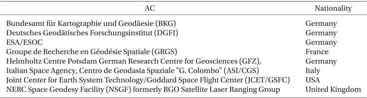
ILRS analysis centers (AC) (http://ilrs.gsfc.nasa.gov/science/analysisCenters/).
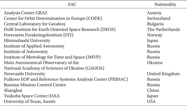
ILRS associate analysis centers (AAC) (http://ilrs.gsfc.nasa.gov/science/analysisCenters/).
The precise orbital and geodetic parameters estimation is the most fundamental procedure of an AC or AAC. In particular, the primary source for AC and AAC products are the results of POD and solutions of a terrestrial reference frame (TRF) and EOPs using SLR observations from SLRdedicated geodetic satellites such as LAGEOS-1, LAGEOS-2, ETALON-1, and ETALON-2. Therefore, an organization that is trying to operate an AC or AAC must generate the results of POD and solutions of a TRF and EOPs using SLR observations from SLR-dedicated geodetic satellites. In Korea, the accurate ranging system for geodetic observation mobile (ARGO-M) of the Korea Astronomy and Space Science Institute (KASI) has been developed (Jo et al. 2011, Park et al. 2012). A preliminary study on SLR data processing, at a level suitable for ILRS AAC, was performed by POD of LAGEOS-1, LAGEOS-2, ETALON-1, and ETALON-2 using SLR observations (Kim et al. 2012). To secure the SLR data processing technology, at a level for ILRS AAC, it is necessary to obtain solutions of a TRF and EOPs for SLR-dedicated geodetic satellites.
In this study, as research for preparing an ILRS AAC, we performed precise orbital and geodetic parameter estimation using SLR observations. We analyzed POD results and solutions of a TRF and EOPs for LAGEOS-1, LAGEOS-2, ETALON-1, and ETALON-2, the representative SLR-dedicated geodetic satellites. The GEODYN II and SOLVE software programs developed by NASA/GSFC were used for precise orbital and geodetic parameter estimation (Pavlis et al. 1998, Ullman 2010). Normal point (NP) data from ILRS stations in consolidated laser ranging data format (CRD) were used for measurements. To verify our orbit solutions, we first analyzed the POD results of LAGEOS-1, LAGEOS-2, ETALON-1, and ETALON-2 by post-fit residuals. Next, we performed a precision analysis of our solutions by applying both a stability analysis of TRF and an external comparison of EOPs with solution, EOP 08 C04 (http:// hpiers.obspm.fr/eop-pc/) by International Earth rotation and Reference systems Service (IERS).
2. PRECISE ORBIT DETERMINATION
2.1 Satellites for Geodetic Missions
In July 2013, 40 SLR satellites are carrying out their missions, excluding the LLR-related satellites (http:// ilrs.gsfc.nasa.gov/satellite_missions/current_missions/). Among SLR satellites, LAGEOS-1, LAGEOS-2, ETALON-1, and ETALON-2 are the most representative geodetic satellites. These satellites have been playing a key role in studies on geodynamics, geodesy, and satellite orbital motion, and in related research areas. Information about each satellite is presented in Table 3 (http://ilrs.gsfc.nasa. gov/satellite_missions). As seen in the table, because LAGEOS-1, LAGEOS-2, ETALON-1, and ETALON-2 have spherical shapes, a perturbation model of solar radiation pressure, for example, can be simplified. As these satellites occupy altitudes greater than 5,000 km, the air drag effect is weak. Recently, the precisions of post-fit residuals of LAGEOS-1 and LAGEOS-2 are as small as 1 cm (Sośnica et al. 2012). A precise modeling of perturbations and the precisions of estimation results are key points of geodetic parameter estimation problems. Thus, LAGEOS-1, LAGEOS-2, ETALON-1, and ETALON-2 are, arguably, the best tools for verifying the results of precise orbital and geodetic parameter estimation.
[Table 3.] Satellites of geodetic missions (http://ilrs.gsfc.nasa.gov/missions/satellite_missions).
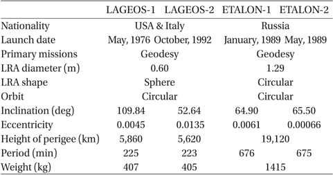
Satellites of geodetic missions (http://ilrs.gsfc.nasa.gov/missions/satellite_missions).
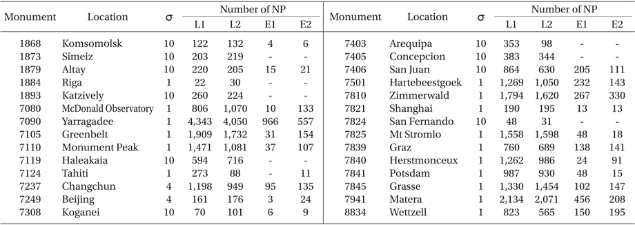
POD finds the state vector of an orbiting satellite at a specific time by using satellite tracking measurements and an estimation theory (Noomen 2001). In SLR data processing, POD is the essential procedure for geodetic parameter estimation. In this study, weekly-based POD was performed by the NASA/GSFC GEODYN II software using SLR CRD NP data of LAGEOS-1, LAGEOS-2, ETALON-1, and ETALON-2. SLR CRD NP data were obtained from an ftp server (ftp://cddis.gsfc.nasa.gov/pub/slr/data) by the crustal dynamics data information system (CDDIS) at NASA (Noll 2010). SLR observations from 24 ILRS stations, which were collected for 20 weeks from 7 January to 20 May, 2013, were used. Information about the ILRS stations and SLR NP observations for POD is displayed in Table 4. The NP number of LAGEOS is generally larger than that of ETALON, since the NP bin size of LAGEOS is shorter than that of ETALON. The NP bin size of LAGEOS is shorter than that of ETALON. The NP bin size of LAGEOS is 120 s while that of ETALON is 300 s. In Table 4, σ is the observationweighting sigma value of a station for GEODYN II input cards of POD. If σ>1 for a station, then the NPs of that station are underweighted by as much as the σ-value in the POD process. Therefore, ILRS stations for which 3 the crustal dynamics data information
[Table 4.] Information about ILRS stations and SLR normal points for precise orbit determination.

Information about ILRS stations and SLR normal points for precise orbit determination.
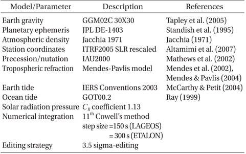
Table 5 summarizes the model information of GEODYN II. The GRACE gravity model (GGM02C) for Earth gravity field modeling (Tapley et al. 2005) was used. The dimensions of the gravity field are limited to 30 because there is no difference between LAGEOS orbits using a degree of the gravity field above 30 (Sośnica et al. 2012). For the planetary ephemeris of the Sun, the Moon, or the planets in the solar system, the Jet Propulsion Laboratory (JPL) DE-1403 that is derived from DE-403 was ussed (Standish et al.1995). For atmospheric density modeling, the Jacchia model was applied (Jacchia 1971). The ITRF2005 SLR rescaled coordinates (Altamimi et al. 2007) and the IAU2000 model (Mathews et al. 2002) were used for station coordinates and the precession- and nutation-related values, respectively. The Mendes-Pavlis model (Mendes et al. 2002, Mendes & Pavlis 2004) was used for tropospheric delay modeling, and the IERS Conventions 2003 (McCarthy & Petit 2004) and GOT00.2 (Ray 1999) were applied to account for Earth and ocean tides, respectively. The solar radiation pressure coefficient,
[Table 5.] Dynamic and measurement models for POD.

Dynamic and measurement models for POD.
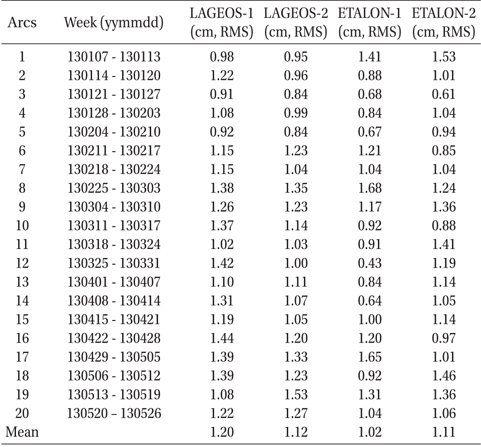
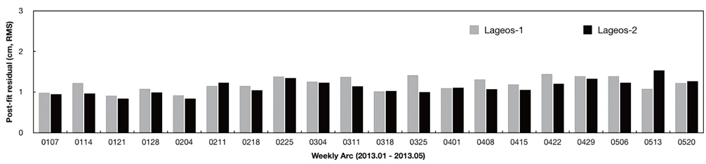
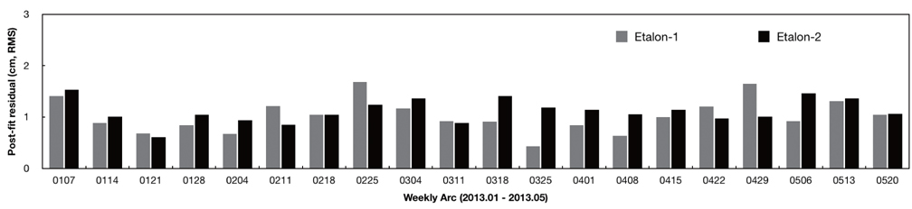
For orbit quality assessment of SLR-dedicated geodetic satellites such as LAGEOS and ETALON, the root mean square (RMS) value of post-fit residuals is commonly used. In this study, the POD results of LAGEOS-1, LAGEOS-2, ETALON-1, and ETALON-2 were analyzed by a post-fit residuals check. The total numbers of NP observations for 20 weeks were 25,287 and 23,484 for LAGEOS-1 and LAGEOS-2, and 2,731 and 2,379 for ETALON-1 and ETALON-2, respectively. After data editing, the numbers of NP observations used for POD processing decreased to 22,845 and 21,519 for LAGEOS-1 and LAGEOS-2 and to 2,504 and 2,200 for ETALON-1 and ETALON-2, respectively. Table 6 shows information about each weekly arc and the RMS values of post-fit residuals of each satellite. The mean RMS values of LAGEOS-1 and LAGEOS-2 are 1.20 cm and 1.12 cm, respectively. Fig. 1 shows the RMS values of postfit residuals for LAGEOS-1 and LAGEOS-2 at each weekly arc. The values of x-axis indicate the first day of each arc. The mean RMS values of ETALON-1 and ETALON-2 are 1.02 cm and 1.11 cm, respectively. Fig. 2 shows the RMS values of post-fit residuals for ETALON-1 and ETALON-2 at each weekly arc. The post-fit residual is the final difference between the observed range and the computed range of the satellite after convergence. Therefore, it shows how well the determined orbit fits the measurements. The results of post-fit residuals indicate that the precisions of POD results, in this study, are at a 1-cm level. To achieve 1-cm level precision, various geodetic parameters including satellite position and velocity, station coordinates, modeling coefficients of perturbations, and related values must be estimated very precisely. Moreover, the choice of the data editing and observation weighting of each station is a critical factor to obtain 1-cm level orbits. In this study, all these factors are considered carefully, and precise orbits of 1-cm level precision were finally obtained. In particular, the generation of cm-level orbits of LAGEOS-1 and LAGEOS-2 is an essential part of ILRS AC data processing. Kim et al. (2012) summarized previous orbit precisions of LAGEOS and showed that the quality of LAGEOS orbits can reach a 1-cm level. Recently, the precision of LAGEOS orbits has improved to be less than 1 cm (Sośnica et al. 2012). Therefore, in this study, the precision of POD results is important for ILRS AAC.
[Table 6.] Information about arcs and results of post-fit residuals.

Information about arcs and results of post-fit residuals.
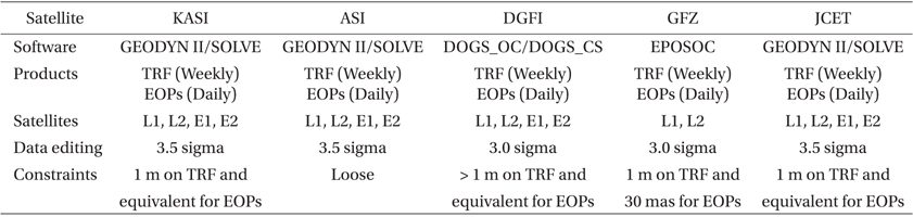
Weekly-based solutions of TRF and EOPs are one of the main products of ILRS ACs. Strategies to obtain solutions of TRF and EOPs for this study and four ACs are summarized in Table 7. Details of the strategies for generating TRF and EOPs of each AC are summarized in a description of ACs in CDDIS (ftp://cddis.gsfc.nasa.gov/slr/ products/ac/) and the so-called pos+eop product of ACs in CDDIS (ftp://cddis.gsfc.nasa.gov.slr/products/pos+eop/). Most ACs of ILRS employ the POD results of LAGEOS-1, LAGEOS-2, ETALON-1, and ETALON-2 to generate a weekly solution of TRF and a daily solution of EOPs. Each AC uses different editing and constraint strategies for SLR data processing and a combination of POD results from each satellite, respectively. Constraints mean that prior values (standard deviation) of TRF and EOPs are restricted within proper values, which are based on a requirement for each space-geodetic technique. For SLR observations, ILRS recommends loosely constrained solution with a prior standard deviation on TRF and EOPs exceeding 1 m for consistency. Loosely constrained solution is based on the assumption that the uncertainty of a solution is large relative to a reference. The details of loosely constrained solutions are illustrated by Heflin et al. (1992), Blewitt (1998), Davies & Blewitt (2000), Bianco et al. (2003), and Coulot et al. (2010). For SLR-based solutions, loosely constrained approach is a standard strategy to combine solutions using various space-geodetic techniques (Altamimi et al. 2007, 2011). In this study, we followed the strategy of AC and recommendations of ILRS to obtain solutions of TRF and EOPs using POD results of LAGEOS-1, LAGEOS-2, ETALON-1, and ETALON-2. Loosely constrained scheme with an a priori value (standard deviation) on both TRF and EOPs of 1 m was applied for solutions.
[Table 7.] Strategies for solutions of TRF and EOPs.

Strategies for solutions of TRF and EOPs.
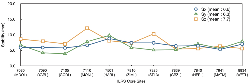
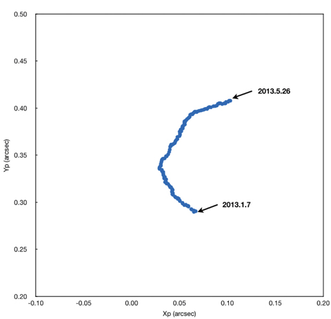
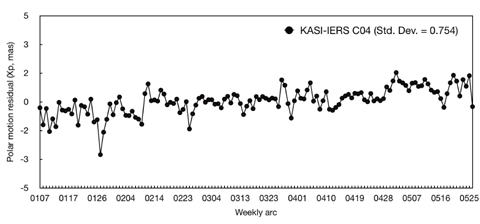
The stabilities of each station coordinate were analyzed to verify our TRF solution (KASI-TRF-solution). Eleven ILRS core sites, which are ILRS stations with a long-term tracking history and a stable data quality and continuity (http://ilrs.gsfc.nasa.gov/docs/ILRS_contribution_to_ITRF2008.pdf ), were used for verification by performing a stability analysis of KASI-TRF-solution. The eleven ILRS core sites are: 7080 (McDonald, TX, USA), 7090 (Yarragadee, Australia), 7105 (Greenbelt, MD, USA), 7110 (Monument Peak, CA, USA), 7501 (Hartebeesthoek, South Africa), 7810 (Zimmerwald, Switzerland), 7825 (Mount Stromlo, Australia), 7839 (Graz, Austria), 7840 (Herstmonceux, UK), 7941 (Matera, Italy), and 8834 (Wettzell, Germany). Table 4 shows that the observation-weighting σ values of the 11 ILRS core sites are 1, which means that SLR NP observations of these stations show good performance. For precision assessment of our solution of EOPs (KASI-EOPs-solution), an external comparison to IERS EOP time series IERS 08 C04 results was made. Polar motion, denoted
For the KASI-TRF-solution, geocentric station coordinates (
where
The following steps are processed for a stability analysis . First, a TRF solution at each are is obtained in which the epoch occurs at the midpoint of a week; for example, from 7 to 13 January, the reference epoch occurs at noon on 10 January. Next, the state positions of solutions are converted to values at the epoch of the first week (i.e. noon at 10 January) using the station velocities of ITRF2005. Finally, the station positions at the same epoch are compared by stability analysis. Table 8 shows the stabilities of each direction (
[Table 8.] Stabilities of the positions of ILRS core sites.
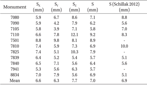
Stabilities of the positions of ILRS core sites.
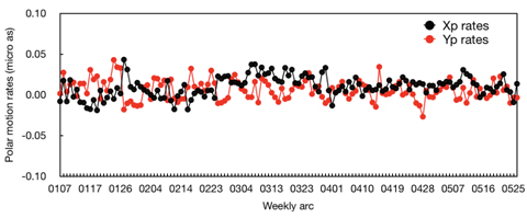
For the KASI-EOPs-solution, polar motion
In this study, we performed precise orbital and geodetic parameter estimation using SLR observations and validated results of POD and solutions of TRF and EOPs to prepare for ILRS AAC. We used SLR CRD NP observations of LAGEOS-1, LAGEOS-2, ETALON-1, and ETALON-2 for 20 weeks from 7 January to 20 May, 2013 and NASA/GSFC GEODYN II and SOLVE software. As a result of the verification of POD results, we obtained post-fit residuals at a level of 1-cm RMS for four satellites. Stability analysis was performed for validation of the KASI-TRF-solution, and results show that the mean 3D stability of coordinates of 11 ILRS core sites in the KASI- TRF-solution has a precision level of 7.0 mm. This result is consistent with previous stability analyses of TRF. For precision assessment of the KASI-EOPs-solution, external comparisons with respect to IERS 08 C04 EOP series were performed. Results show that the precision of KASI-EOPs-solution is comparable to that of previous research. One of the most important products of ILRS AAC and AC is the 1-cm level POD results of SLR-dedicated geodetic satellites such as LAGEOS and ETALON and weekly-based solutions of TRF and EOPs. In conclusion, our results of precise orbital and geodetic parameter estimation using GEODYN II and SOLVE software constitute a significant achievement in the preparation of an ILRS AAC in the performance and results of SLR data processing.