Lava caves could be useful as outposts for the human exploration of the Moon. Lava caves or lava tubes are formed when the external surface of the lava flows cools more quickly to make a hardened crust over subsurface lava flows. The lava flow eventually ceases and drains out of the tube, leaving an empty space. The frail part of the ceiling of lava tube could collapse to expose the entrance to the lava tubes which is called a pit crater. Several pit craters with the diameter of around 100 meters have been found by analyzing the data of SELENE and LRO lunar missions. It is hard to use these pit craters for outposts since these are too large in scale. In this study, small scale pit craters which are fit for outposts have been investigated using the NAC image data of LROC. Several topographic patterns which are believed to be lunar caves have been found and the similar pit craters of the Earth were compared and analyzed to identify caves. For this analysis, the image data of satellites and aerial photographs are collected and classified to construct a database. Several pit craters analogous to lunar pit craters were derived and a morphological pit crater model was generated using the 3D printer based on this database.
The first-ever human landing on the Moon by Neil Armstrong of USA in 1969 opened up new vistas of the human future and suggested a possibility of human habitat on extraterrestrial celestial bodies. Since several lunar landings have been achieved successfully up to the present and the base on the Moon which is the nearest, the most familiar celestial body, will be an essential outpost for the human exploration of the space.
Prior to the construction of the lunar base, topographical features should be reviewed in advance and the caves on the lunar surfaces have been of primary interest (Horz 1985, Coombs & Hawke 1992). Caves provide features of basic habitation as a natural shelter and they had been used as residential spaces in the primitive Earth. Similarly, caves could serve as residential spaces and warehouses for the storage of exploration equipment transported from the Earth when the extraterrestrial celestial bodies are explored and considered for settlements in the future.
While the base construction on the lunar surface would require huge shipping costs to transport construction materials of posts or ceilings from the Earth to the Moon, it is more efficient and economical to build a base in the caves which requires only the inflatable structures to seal the cave.
Most of the high energy particles of cosmic rays could be shielded at or below 6 meters under the surface according to De Angelis et al. (2002). Therefore, caves could provide a shelter from the cosmic rays and meteorite impacts from the outer space. Also, caves are well-insulated compared to the lunar surface which shows big daily temperature differences and it is easy to control the temperature in the caves with a proper shielding of the cave entrance.
From a morphological perspective, there are lots of craters all over the surface of the Moon created by the impacts of outer celestial bodies such as meteorites.
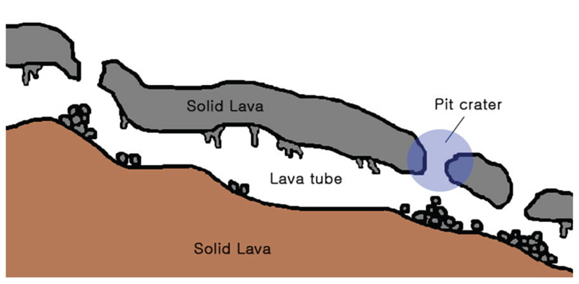
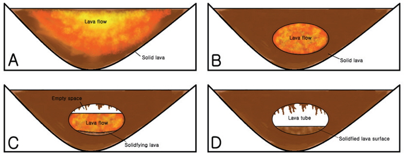
The heat and energy generated by the impacts melt the crust of the Moon, and lava tubes are formed during the topographical change of crust melting. Lava tubes were discovered by many others (Oberbeck et al. 1969, Oberbeck 1971, Greeley et al. 1971, Cruikshank & Wood 1972, Head 1976) and lunar lava tubes show similar structures as those created by the volcanic activities of the Earth. The mechanism of lava tube formation is described briefly in Fig. 1.
Lava is formed and flows on the surface ground. As time elapses, the outer surface of lava cools down to be solidified while the inner lava flows through. Lava flow subsides and an empty space is created A lava tube is formed as the lava flows out and solidified completely.
Lava tubes of the Earth are created through this process and pit craters are formed when the ceiling collapses by diastrophism or the external impacts of meteorite. The pit craters serve as entrances to lava tubes (Fig. 2).
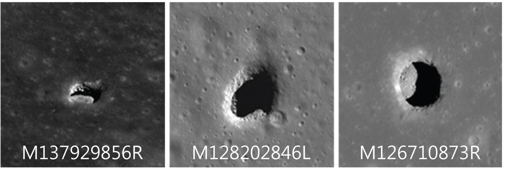
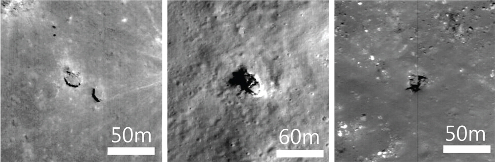
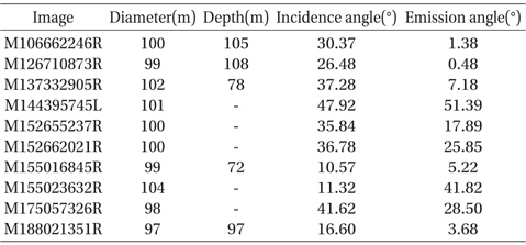
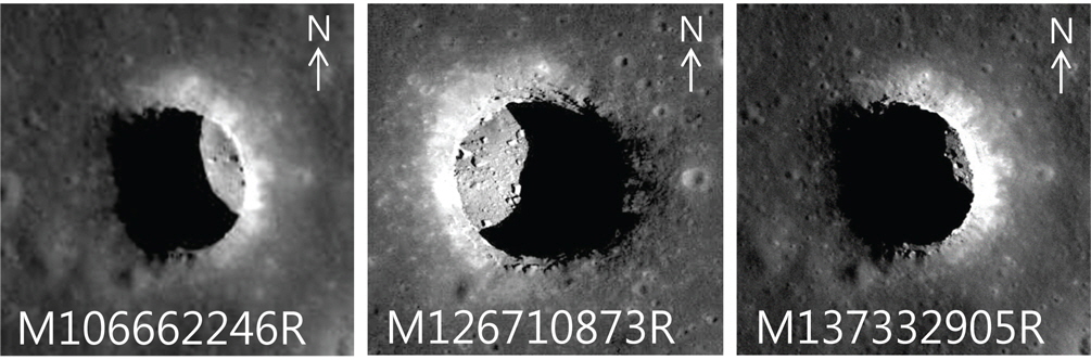
Several pit craters were discovered by the Terrain Camera (TC) of SELENE and the Lunar Reconnaissance Orbiter Camera (LROC)/Narrow Angle Camera (NAC) of LRO (Haruyama et al. 2009, 2010, 2011, see also Ashley et al. 2011). However, those craters are over 60 m in diameter and are not appropriate for an initial base station since they require construction materials and equipments on a large scale, which is not economical. Small scale craters less than 50 m compensate these demerits. They could serve as a proper habitat for a small group of people and do not require construction materials in large volumes. Recently, it has been reported that 20~200 pit craters less than 50 m in size are scattered all over the surface of the Moon (Robinson et al. 2012). These small scale craters are of primary interest for this study. Pit craters discovered by the SELENE mission and the LRO mission are shown in Fig. 3 and the informations on the pit craters are listed in Table 1(Haruyama et al., 2009, 2010, 2011; Ashley at al., 2011).
[Table 1.] Lunar large scale pit crater information.
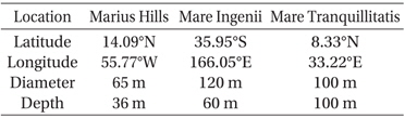
Lunar large scale pit crater information.
Although the number and the locations of lunar pit craters have been reported, the detailed information of latitudes and longitudes is not specified. Thus the pit crater locations are found by investigating the image data of LROC/NAC of the LRO mission. The latitude and the longitude indicated by Act-React Quick Map supported by the LROC Team in Arizona State University in USA was used to find the locations of pit craters;location of Act-React Quick Map has a standard deviation about 10 m(Wagner et al., 2014). At first, 3 craters of Aristarchus, King, and Stevinus were investigated before the full investigation of the 20 craters.
Also the depths of pit craters were estimated to find out the shielding capability against high energy particles from the outer space. In order to obtain the depth of a pit crater, different approaches are taken depending on the visibility of the floor of pit crater. The depths of small scale craters can be estimated only when the floor is visible. When the view of floor is not allowed, the size of inner wall should be available to estimate the depth while the small scale pit crater could not provide this information due to the limitation on the resolution of camera. Therefore the depths of pit craters were obtained only for the caves of when the view of the floor is allowed. The depth is given as Equation (1) (Haruyama et al. 2009).

where ‘D’ indicates the depth, ‘L’ is the true length of shadow, and ‘i’ represents the incident angle of solar light.
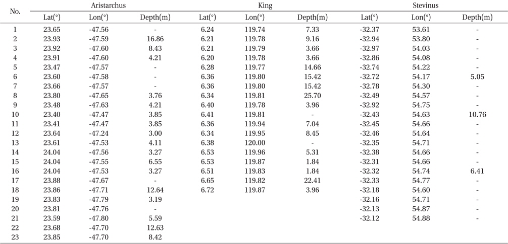
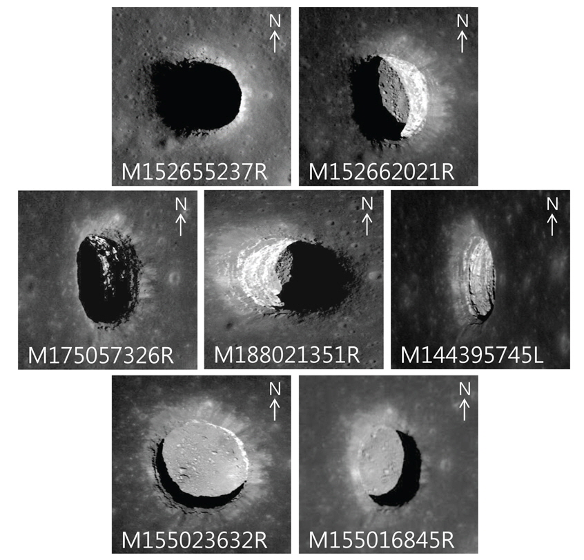
Latitudes, longitudes, and depths of the pit craters determined in this way are shown in Table 2 for 3 craters investigated and some of the pit craters are shown in Fig. 4.
[Table 2.] Location information of lunar pit craters.

Location information of lunar pit craters.
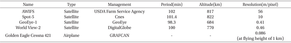
[Table 3.] Satellite and airplane that provide picture to Google Earth.

Satellite and airplane that provide picture to Google Earth.
Although several topographical patterns presumed as pit craters have been found, there is no evidence to confirm that since it is not practical to explore the Moon for now and the analyzed images have the limited resolution. In order to overcome these barriers, similar topographical structures on the Earth were investigated. There exist pit craters and lava tubes on the Earth also and most of the pit craters serve as the entrance of caves. Thus, the analogous topographical patterns on the Earth were investigated in order to verify the lunar pit craters.
The terrestrial data was obtained from Google Earth which is provided by Google Inc. for geographical information services. There are various providers to give geography information to Google Earth and they supply images of various resolutions using variety of equipments. The brief informations on satellites, aerial equipments, and resolutions of each provider are summarized in Table 3.
2.2 3D structure of pit crater
It would be helpful to investigate three large scale pit craters discovered already to figure out the structure of small scale pit craters. Among those craters, the one in Mare Tranquillitatis shows a circular shape and gives a good visibility of the floor. Also satellite images of the crater taken at different times show inner spaces wider than the area of the entrance due to the difference in the incident angle and the emission angle of solar light. The incident angle indicates the angle between the solar light and the normal direction to the surface of the Moon. The emission angle indicates the angle between the normal direction to the camera lens and the normal direction to the surface of the Moon. The inner space wider than the area of the entrance could suggest the existence of lava tube in the pit crater (Robinson et al. 2012).
3D model of the pit crater in Mare Tranquillitatis was developed to figure out the structure clearly. The crater was selected since it is the biggest one among three large scale craters. Both the diameter and the depth of the crater are 100 m which are large enough to enable the deciphering of the images with ease. Also many images taken at different times to show different incident angles and emission angles are provided to figure out the geometry accurately. The informations of the diameter, the incident angle, and the emission angle are required to generate the 3D model of the crater. The maximum diameter measured from the various images was used as a reference and the depth was obtained from the results of Robinson et al. (2012) (Table 4). The images used are shown in Figs. 5 and 6. Among the results of Robinson et al. (2012), the cases with no visibility of inner wall or floor and the cases whose shadow lengths are not possible to be estimated are excluded from the generation of 3D models because the depths cannot be determined.
[Table 4.] Information of Mare Tranquillitatis pit crater.

Information of Mare Tranquillitatis pit crater.
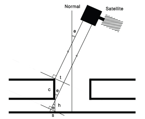
The above images show that the inner space of pit craters are wider than the area of the entrance and it is necessary to measure the size of the inner space for the 3D model development. The size of inner space is obtained based on the emission angle and the scale of the images. However the size of the inner space might be bigger since the size is estimated based on the image data only.
There are several assumptions to calculate the size of inner space. First, the lunar surface is assumed to be flat and the complicated surface shapes are neglected to simplify the calculation. Second, the side wall is assumed to collapse vertically to the surface. Third, the diameter of the crater is assumed to be 100 m although there are differences depending on the images. Finally, the depth is assumed to be 100 m although it is in the range of 72 m and 108 m.
In order to calculate the size of inner space, we have to know the height of inner space. The thickness of ceiling should be obtained beforehand to determine the height and it is calculated as follows.

Where c is the actual thickness of the ceiling, t is the calculated thickness determined from the images considering scale, and e is the emission angle. Then the height of inner space, h, is given as Equation (3).

Using the height and the emission angle, the size of inner space, s, is determined using Equation

Finally, the size can be represented as follows using the firsthand data.

The size of inner space, s, determined in this approach is 14 meters. If the inner space extends to all directions, the diameter of the floor would be at least 128 meters. The space of 14 meter width provides a sufficient living space for humans.
In addition to the inner space of 14 meters, the existence of a lava tube to a direction is assumed for the generation of the 3D model. We should consider the volume of crust materials which were collapsed during the creation of pit craters. The depth is assumed to be 100 meters and the thickness of ceiling was calculated to be 70 meters. The volume of collapsed materials was calculated to be 175,000π m3 using to the volume formula of a simple circular cylinder. If we assume that the materials are accumulated on the flat surface, it would take the form of right circular cone. When pebble, sand, and soil are accumulated on the ground, they would also take the form of cone and the angel between the cone surface and the ground are known to be 30 degrees (Choi 2004). The radius of cone is calculated to be √3 h for the height, h, and the angle of 30 degrees. Since the volume of a right cone is 1/3 of the volume of a right cylinder Equation (6) holds true.

Rearranging for h gives,
Therefore, the height of the cone is 56 m and the radius of the cone bottom is 97 m. However, this would be true only in case of the floor surface of the crater larger than 97 m of radius. Since our 3D model of lava tube has narrower floor surface there are deviations in cone height and radius to show slightly higher value(Fig. 7).
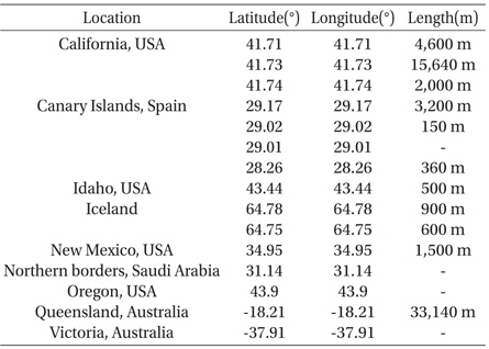
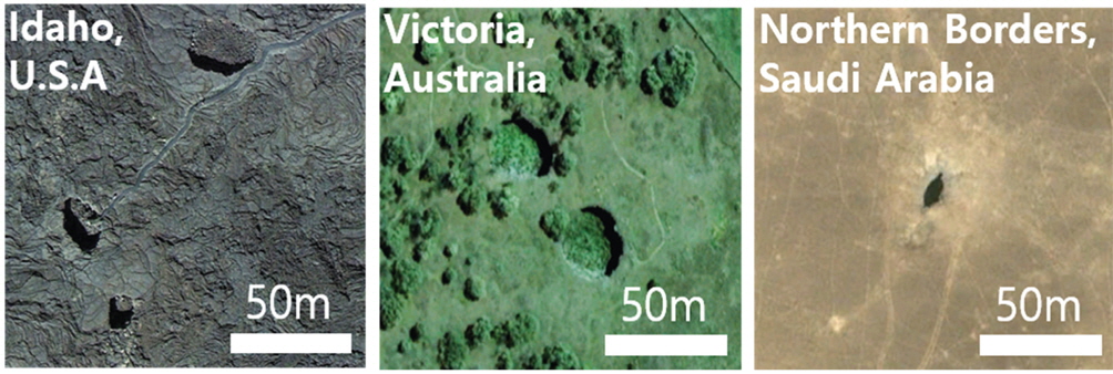
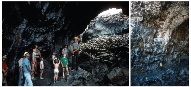
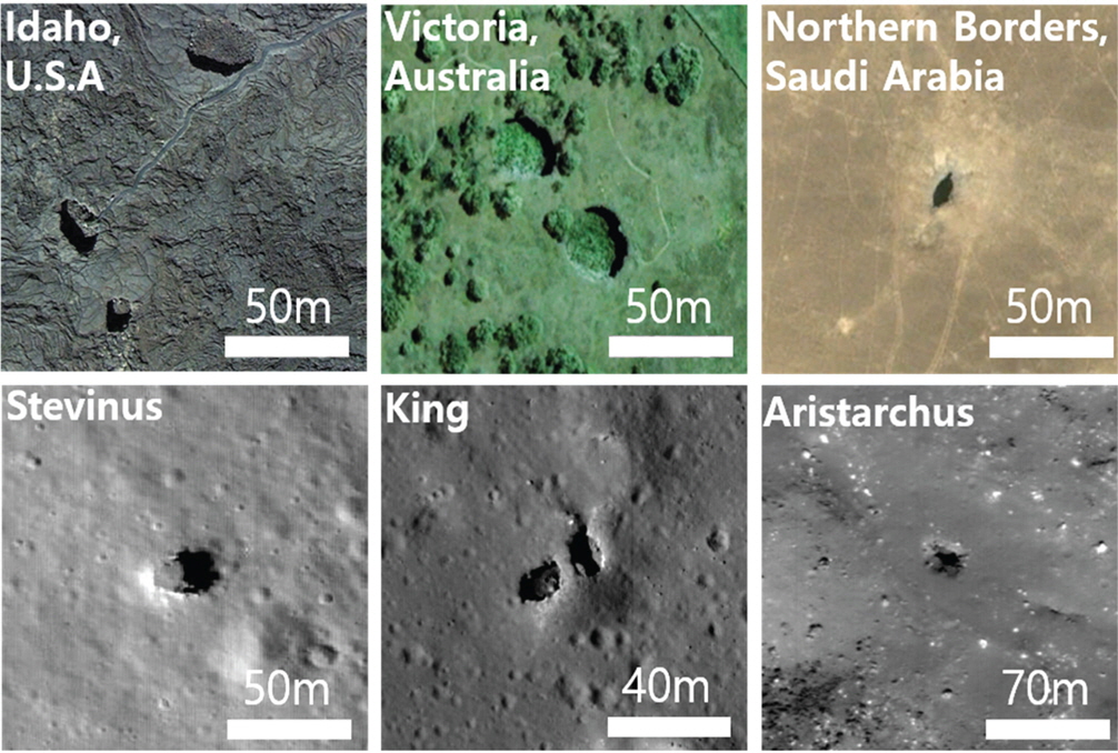
We have found several caves using Google Earth and classified their topographical data systematically to construct a database. The criteria for classification are country, location, latitude, longitude, and length of lava tube as summarized in Table 5. Fig. 8 shows the aerial photographs for the arbitrarily chosen 3 locations. An inner view of Idaho pit crater is shown in Fig. 9.
The actual images of pit craters on the Earth in the database reveals that those are open to the sky as shown in Fig. 8 and the openings serve as the entrance of caves. Also as shown in Fig. 9, the inner space is large enough to be a habitat for humans.
In order to show that the pit craters in Table 2 are entrances to the lunar caves based on the topographical resemblance of the image data obtained from LROC and Google Earth. The satellite images of the Earth and the Moon were compared in Fig. 10.
As shown in the figures, pit craters on the Earth show abrupt changes in shade same as in lunar craters. Also, the colors of the perimeter are brighter than the surroundings and the other characteristics also show similarities each other. Using the image data of the Earth is advantageous in that the direct approach is possible to provide inner and outer shape and the resolution of the image is higher than the lunar images enabling precise identification.
[Table 5.] Terrestrial lava tube information.

Terrestrial lava tube information.
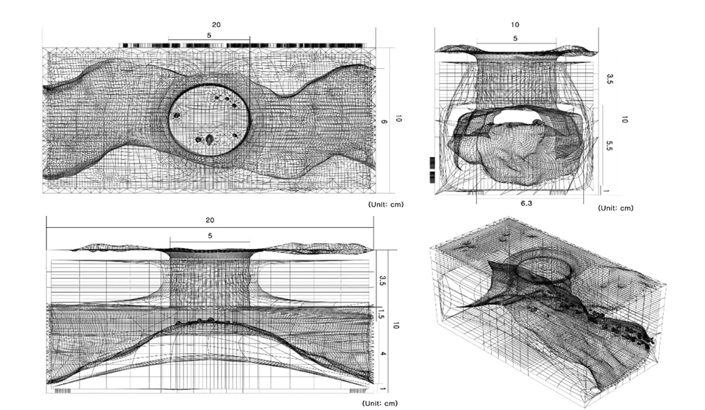
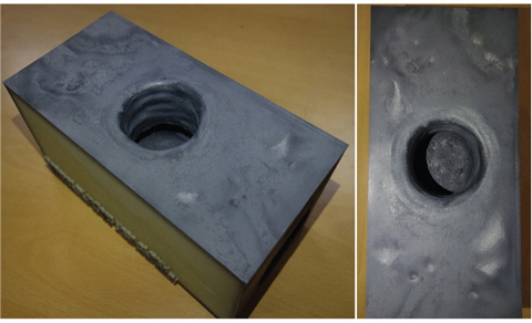
Actual 3D model was produced using the 3D printer at Da Vinci Lab of Korea Aerospace Research Institute (KARI). We used 3DS MAX software of Autodesk Inc. for designing 3D model. The dimension of model is 20×10×10 cm with a shape of rectangular parallel piped. The diameter of pit crater is 5 cm. The height of the collapsed ceiling material should be 2.5~3 cm considering the 56 m height of the cone shape accumulated on a flat surface. However, the height was increased to 4 cm taking into account of accumulation on the lava tube rather than a flat surface. The height of the cone should be calculated more precisely for the subsequent revision of model. The cross section of lava tube was set to 6 cm considering the diameter of 130 m considering the bigger radius than the entrance (Fig. 11). The replica model printed by the 3D printer shows changes in phases depending on the directions of light and the camera angles, and shows the similar patterns of satellite images (Fig. 12).
Systematic standards are required to find lunar pit craters as candidates of human habitat on extraterrestrial celestial bodies to provide a shelter from external impacts. Although the terrestrial pit craters are formed by the volcanic activities unlike the lunar pit craters formed through meteorite impacts, they show similar topographical shapes each other. Therefore, it is appropriate to establish these standards based on the terrestrial pit craters of which the topographical structures resembles those of lunar pit craters.
In this study, comparative analysis was performed between the terrestrial pit craters and the small scale lunar pit craters which are suitable for lunar outposts from a morphological perspective. The topographical similarities have been revealed between the pit craters of the Earth and the Moon. Also, the database of topographical shapes of the Earth was constructed as a result of this study. The database is not yet complete since there’s a good possibility of finding new or missing data. We will continue to update the database to add data to achieve completeness. It will be of great help to use this database to find a small scale lunar pit craters for comparison purposes.
Also, the 3D model of a pit crater was produced based on a large scale pit crater applying several assumptions. It would be also applicable to a small scale pit crater if the dependency of the structures on the scale of the crater is not negligible. Making the actual 3D model of a pit crater utilizing 3D printer will be an effective means to introduce the lunar caves to the public and academia.