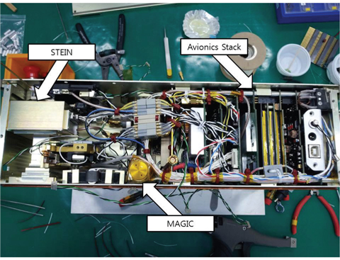
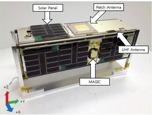
TRiplet Ionospheric Observatory-CubeSat for Ion, Neutron, Electron & MAgnetic fields (TRIO-CINEMA) is a CubeSat with 3.14 kg in weight and 3-U (10 × 10 × 30 cm) in size with a plasma particle payload, Supra-Thermal Electron and Ion and Neutral (STEIN) and a magnetometer measuring the magnetic fields of near earth space, MAGnetometer Imperial College (MAGIC). TRIO-CINEMA has been jointly developed by Kyung Hee University and UC Berkeley. The satellite is scheduled to be launched into the sun-synchronous orbit at the height of about 700 km and an inclination angle of 98.57° via Dnepr launch vehicle at Yasny Cosmodrome in Russia in November 21, 2013. TRIO-CINEMA has the exterior structure in which MAGIC is located at +X-axis as shown in Fig. 1. Fig. 2 demonstrates the interior structure.
A satellite will be exposed to the extreme environment of extreme low temperature and high vacuum in the space. In such an environment, thermal stability needs to be ensured so that all components of the satellite can be maintained within the allowable limit range for the satellite to conduct its mission (Lee et al. 2011). For the proper control of the satellite temperature in the space environment, a thermal control design is undertaken, and orbit environmental tests are conducted within the high vacuum and thermal vacuum chamber made on the ground to verify the satellite’s thermal control design (Jun et al. 2009).-
This paper demonstrates the construction of the thermal vacuum test environment by changing the shroud structure, monitoring system and vacuum chamber for TRIO-CINEMA’s thermal vacuum test. And this paper intends also provided the result of thermal vacuum test results conducted by determining temperature range of the test, based on the thermal analysis results of TRIO-CINEMA.
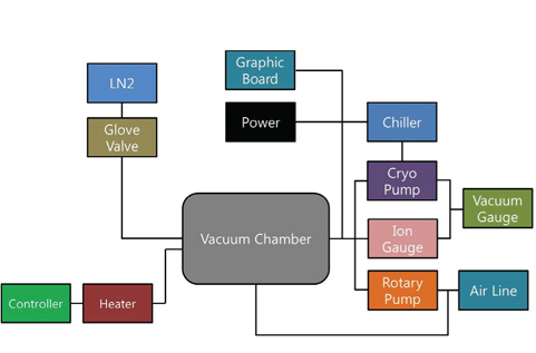
The control mode in the thermal vacuum chamber can be divided into a liquid nitrogen injection mode and a refrigerant circulation mode. The former is a thermal control system using liquid nitrogen and an electric heater, and the latter is a thermal control system that can control heat within wide range of temperature through cooling and heating of refrigerant. The liquid nitrogen injection mode has an advantage of enabling to cool the inside of shroud to ultra-low temperature of -180℃ and below with a simple circulation structure, with a disadvantage of difficulty in temperature control. The mode of using a liquid nitrogen is suitable for experiments in extreme low temperature. The refrigerant circulation mode allows cooling or heating refrigerants by circulating them through the shroud. The mode can precisely conduct low and high temperature thermal control with a disadvantage of costly initial installation cost. This paper describes experiments using the liquid nitrogen injection mode, which has low initial stage installation cost and simple structure for the Kyung Hee University’s thermal vacuum chamber.
The capacity of the vacuum chamber is 750
The thermal control of a thermal vacuum chamber can be divided into cooling and heating. Cooling is conducted in a mode to control liquid nitrogen with the globe valve and flowmeter. The liquid nitrogen is injected into the wall of shroud within the chamber through metallic pipe in order to drop temperature of the central part. Evaporated nitrogen is discharged into a separate pipe, and additional liquid nitrogen should be supplied. As for heating, temperature and temperature change rate are controlled on the coil covering the inside of the shroud using the temperature controller and external output dial. The environmental conditions, such as duty cycle time, temperature and temperature pattern in thermal vacuum test can be set, and each cycle progress can be controlled by the temperature controller. Temperature can be maintained by simultaneous application of cooling and heating that uses liquid nitrogen an electric heater, respectively.
The most efficient system offers the vacuum environment up to 10-6 Torr or less using a turbo molecular pump or Cryo pump (Cho et al. 2007). The thermal vacuum chamber provides two modes for the experiment: First, a rotary pump is used in the case of lowering the pressure up to 10-3 Torr. For less than 10-3 Torr, a Cyro pump uses the principle of removing air by letting gas molecules to be condensed or absorbed on the cold surface. The mode cools lower part surface of the vacuum chamber with helium down to 10 K. It is used to reduce vacuum down to 10-5 Torr.
The cooling of Cyro pump is made using a water-cooled chiller. Also, the main valve connecting to the chamber and Cyro pump blocks back flow of air, the foreline value connecting to the rotary pump and Cyro pump. And the roughing valve connecting to the chamber and rotary pump are set not to open simultaneously with other closed valves. The vacuum monitoring panel indicates the vacuum of the Cyro pump and vacuum of the rotary pump. Vacuum with less than 10-3 Torr is indicated by measuring it with an ion gauge.
3. CONSTRUCTION OF A THERMAL VACUUM CHAMBER FOR ENVIRONMENT TEST
A system for the test monitoring and data recording during the thermal vacuum test is described in this section. For this system, Laboratory Virtual Instrument Engineering Workbench (LabVIEW), a graphic-based programming, was used LabVIEW, developed by National Instrument Inc. LabVIEW program is a powerful and flexible S/W application development tool for machine control and data analysis. LabVIEW has been continuously used by engineers and scientists in the research, development, production and test fields, and various industries including vehicle, semiconductor, aerospace science, electricity, communications and medicine. LabVIEW is a main tool in the areas of testing, measuring, industrial automation and data analysis (Park 2006).
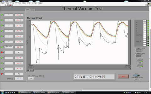
Graphical User Interfaces composed as shown in Fig. 5, and can indicate 12 channels’ temperature information, real time graphs, select graph by channel and record data. In the recorded data, time and sensor’s location and temperatures at various locations are recorded in the Excel file format with a preset time gap. T-type that can measure -250 ~ +350 ℃ was used. The thermocouple inside of the chamber is connected to the outside through 25-pin flange on the chamber wall, using a shielded high voltage cable to protect noise and shock. The connected temperature information is provided to PC from the NI-9213 16Ch Thermocouple Input Module and NI cRio-9022 Real Time Controller with allocated fixed IP. The temperature information provided through LAN connection has a merit that it can also be monitored in real time in places where the program is not installed. NI cRio-9022 Real Time Controller provides shroud’s temperature required for chamber’s heating operation with RS-232.
3.2 Structural modifications of thermal vacuum chamber
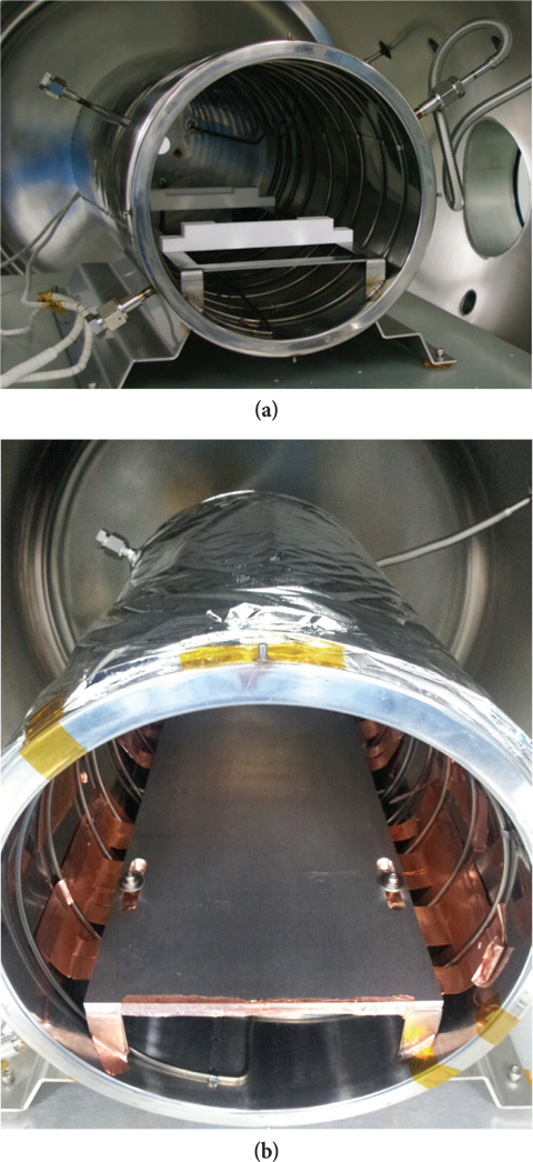
Shroud consists of a cylinder structure with 60 cm in diameter and 80 cm in length. of the pedestal structure to support the satellite in the vacuum chamber is made of Teflon material in Fig. 6a. This satellite support consists of a structure changing the satellite temperature through only radiative transfer of shroud’s heat. However, substantial amount of time was required to cool the satellite with only radiation in view of the shroud’s structure, and thus, shroud’s structural improvement was necessary. The radiated energy discharged outward of the chamber is further blocked by covering the exterior of the shroud with MLI film. The exterior of the shroud was encircled with the net made of polyester material, and KF-6B Aluminized Polyester MLI with 6 μm in thickness in 5-fold laminating structure. After removing the Teflon material-made satellite support, metal plate has been added to enhance the thermal conduction by contacting surface area of this metal plate with thin copper plate of 0.1 mm in thickness with the shroud wall. Fig. 6b demonstrates the image of the modified shroud using MLI film and metal plate. The thermal control mode by such radiation and conduction shows a result of reducing 20% of cooling time, compared with the existing cooling mode conducted by only radiation.
A solenoid valve used for liquid nitrogen injection becomes a cause to make cooling time longer, since it automatically operates by the thermal controller before the preset temperature is reached. Therefore, we moved the solenoid valve and uniform amount of liquid nitrogen could be injected into the shroud by installing a globe valve for extreme temperature, and a flow gauge.
4.1 Result of thermal analysis
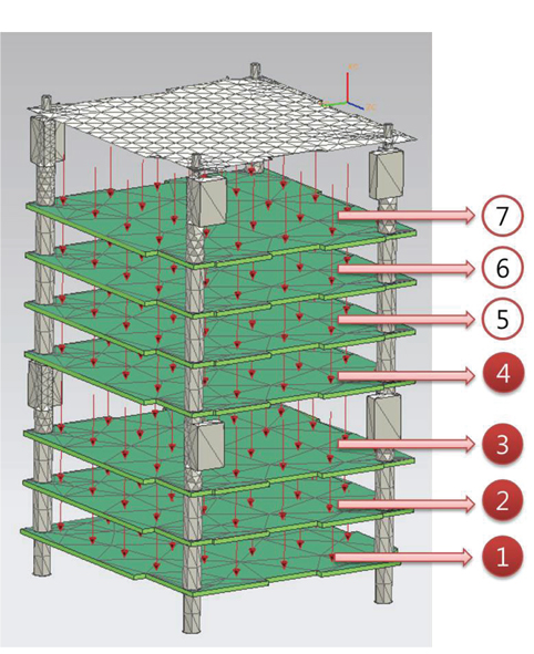
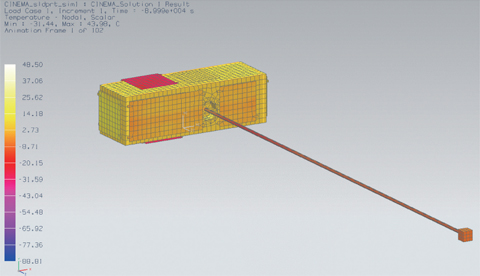
Due to the inherent thermal environment of the mission orbit, simulation of the thermal effect onto the spacecraft reflecting orbital thermal condition should be preceded. In this research, a Computer Aided Engineering (CAE) software tool based on Finite Element Method (FEM), NX6.0, is adopted for thermal analysis by applying CINEMA spacecraft’s structure modeling represented in Fig. 7. In this analysis, the attitude of the spacecraft is the more critical factor than the simple geometry of the CubeSat structure. The attitude of CINEMA is spin stabilized control with 4 Revolution per Minute (RPM), where the spin axis is normal to the ecliptic plane. Therefore, 4 sides of the spacecraft alternatively face the sun except for upper and lower sides.
The internal temperature of the spacecraft is dependent to the operation modes that are safe, science, downlink, and attitude control mode. In this paper, simulation is conducted with respect to the two modes, safe and science mode. In the safe mode which produces the minimum internal temperature, heating is generated by four stacked Printed Circuit Boards (PCB) positioned at ①, ②, ③ and ④ in Fig. 8., whereas the science mode produces the maximum internal temperature by ① to ⑦ PCBs. In addition, this research applied thermo-optical property which indicates material’s outermost surface state. The chassis of TRIO- CINEMA is manufactured by Aluminum 5052-H32 and Aluminum 6061-T6 whereas UHF antenna and STEIN Baffle are manufactured by beryllium copper. Those different material properties are applied by considering each material’s density, conductivity, and thermal capacity (Lee et al. 2006).
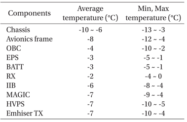
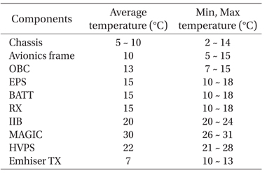
According to this analysis results, temperature changes from the minimum -13 ℃ in the safe mode in the internal board to the maximum +31 ℃ in the science mode, while the spacecraft revolves the earth above 700 km. Such minimum and maximum temperatures are the changes occurring in the outside of the satellite. The temperature changes of the chassis and inside estimated through thermal analysis are summarized in Table 1 and Table 2. The temperature changes of MAGIC outside of the satellite and solar panel are estimated to be -30 ~ +30 ℃ and -55 ~ -10 ℃, respectively. In general, the temperature range of thermal vacuum test is usually set to ±5 ℃ fiducially based on the thermal analysis result in case of acceptance temperature and ±10 ℃ in the case of qualification temperature. In case of TRIO-CINEMA, the operating temperature of most electrical and mechanical components exceed the maximum temperature, +31 ℃, from the result. Furthermore, due to the restricted performance of the vacuum chamber that has long duration of cooling time, it gives a rise to concern that the spacecraft would be affected by exposing low temperature longer duration than the desirable duration. For this reason, the temperature range in this test is set between -20 ℃ ~ +35 ℃, based on the lowest and highest temperatures of satellite chassis and satellite inside in reflection of the median value of acceptance temperature and qualification temperature (David 2001). To set the lower limit temperature, the results of chassis’ thermal analysis is also reflected owing to the fact that solar panel and MAGIC have broad range at low temperature and are directly affected by shroud temperature. One unit test cycle of the thermal vacuum test is set by concerning the temperature range out of the revolving time of the spacecraft around the earth. The temperature changes between -13 ℃ and +31 ℃ and 110 minutes of revolving time concludes the change rate of 0.5 ℃ per minute between -20 ℃ and +35 ℃ (Yoo et al. 2012). Table 3 exhibits the operating temperature range of electric components which will cause critical effect onto the spacecraft system. Most components except battery stratify the temperature range of thermal analysis results. However, the minimum value of operating temperature shows small difference from the lowest temperature of thermal analysis results, compared with the highest temperature. Due to this issue, the lowest temperature of the thermal vacuum test is set at -20 ℃ to verify the status of normal operation of the electric components at low temperature, particularly the operation of the heater at -5 ℃ inside the battery and abnormality at low temperature concerning the battery.
[Table 1.] The min, max temperatures (Safe mode).

The min, max temperatures (Safe mode).
[Table 2.] The min, max temperatures (Science mode).

The min, max temperatures (Science mode).
[Table 3.] Operating temperature ranges of TRIO-CINEMA.

Operating temperature ranges of TRIO-CINEMA.
4.2 Procedure of flight model thermal vacuum test
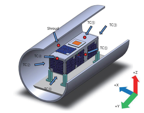
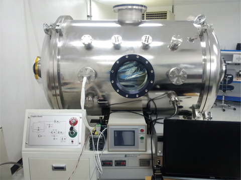
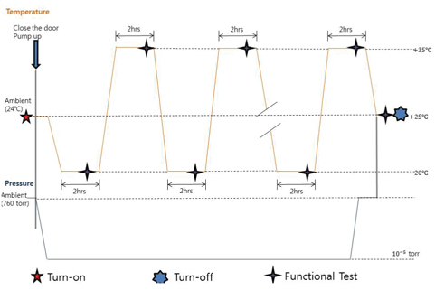
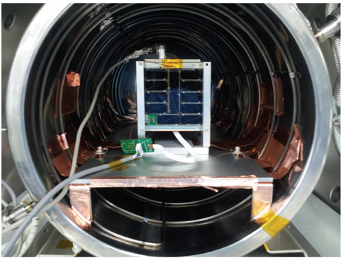
Four cycles of thermal vacuum test is conducted between -20 ℃ and +35 ℃, starting from +20 ℃, which is the temperature of clean room. Fig. 9 demonstrates the details of temperature cycle of the thermal vacuum test. Based on the thermocouple at +Y side, of which temperature change is most constant among the temperature sensors attached to the satellite, two hours of soak time is required, after temperature at the location reaches at -20 ℃ and +35 ℃. After an hour of soak time, functional test of the satellite is carried out. The high vacuum state of 10-5 ~ 10-6 Torr should be maintained according to the temperature in thermal vacuum chamber. In the case of low temperature experiment, shroud temperature is maintained at -100 ℃ and achieved by using only liquid nitrogen. During the soak time, liquid nitrogen and heating coil are used to maintain the satellite temperature at -20 ℃. In the experiment of high temperature chamber, the shroud temperature is increased by heating coil. The temperature of the spacecraft should retain the change rate of 0.5 ℃ per minute. Temperature sensors are attached onto 6 different locations on the surface of TRIO-CINEMA structure and shroud walls for real time monitoring. Fig. 10 demonstrates the location and coordinates axes of thermocouple. Besides the thermocouples, each solar panel and PCBs inside the CubeSat structure has individual temperature sensors. The temperature data collected by the spacecraft are used for the functional test of the electrical system and to check the temperature dependent on different location. As for the attachment of thermocouple on the satellite surface, the thermocouple is fixed with copper tape on the kapton tape. Then, kapton tape is adhered on it again for accurate temperature (Cameron 1999). The attachment location is close to each side’s center, whereas the thermocouple is attached on the edge for narrow space section. The initial functional test is conducted by connecting a USB cable for battery charging and a data communication with external computer through chamber’s flange. Fig. 11 exhibits the initial functional test conducted before starting the thermal vacuum test. The location of the TRIO-CINEMA within the shroud can be identified in the figure.
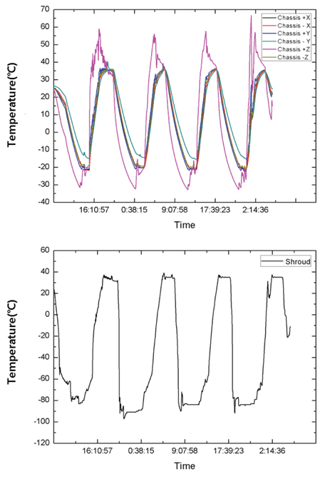
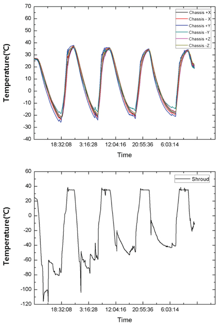
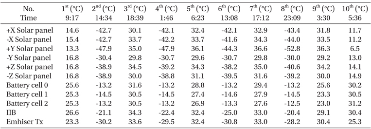
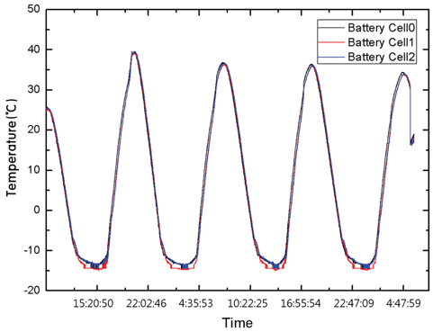
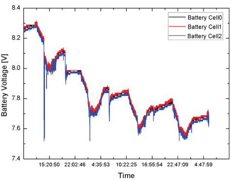
Thermal vacuum test were conducted for the two flight models with the detailed procedure mentioned in the above section. Fig. 12 shows the outside temperatures of the structure and shroud from the thermal vacuum test of TRIO-CINEMA2. Thermocouples were attached on the six sides of satellite outside and returned temperature change between -20 ℃ and +35 ℃, according to shroud temperature change. +Z side which is the closest to the shroud showed relatively wider temperature change, compared with other sides. As for the time required for one cycle, four hours and eight hours were required for heating and cooling including soak time, respectively. During the experiment, cooling time was extended up to 9 hours due to abnormality of nitrogen pipe during the experiment. Fig. 13 represents the temperature change graph of outside and shroud of TRIO-CINEMA3. Temperature change at +Z side closest to the shroud is the highest temperature. In case of TRIO-CINEMA2 experiment, shroud temperature change was constant. Thus, three-hours-shorter cooling time was demonstrated. Tables 4 and 5 show the lowest and highest temperatures of solar panels and PCBs inside the satellite per cycle. The lowest and highest temperatures of solar panels are shown on the +Y panels of both TRIO-CINEMA2 and TRIO-CINEMA3. Although +Z solar panel is the closest location to shroud, the lowest and the highest temperature were recorded on the +Y solar panel. It is because the temperature sensor on the +Y solar panel is attached on the panel, whereas the temperature of the +Z solar panel is attached under the panel. As for the battery deviating from operating temperature range, its temperature is higher at least 10 ℃compared to Instrument Interface Board (IIB) which is the most adjacent board. It is considered that the heater is normally operated by considering increased power consumption at the designated temperature. Figs. 14 and 15 show temperature and voltage changes in the thermal vacuum test cycle of the battery.
[Table 4.] The min, max temperature of inside and solar panel (TRIO-CINEMA2).

The min, max temperature of inside and solar panel (TRIO-CINEMA2).
[Table 5.] The min, max temperature of inside and solar panel (TRIO-CINEMA3).
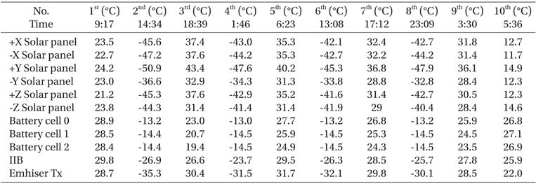
The min, max temperature of inside and solar panel (TRIO-CINEMA3).
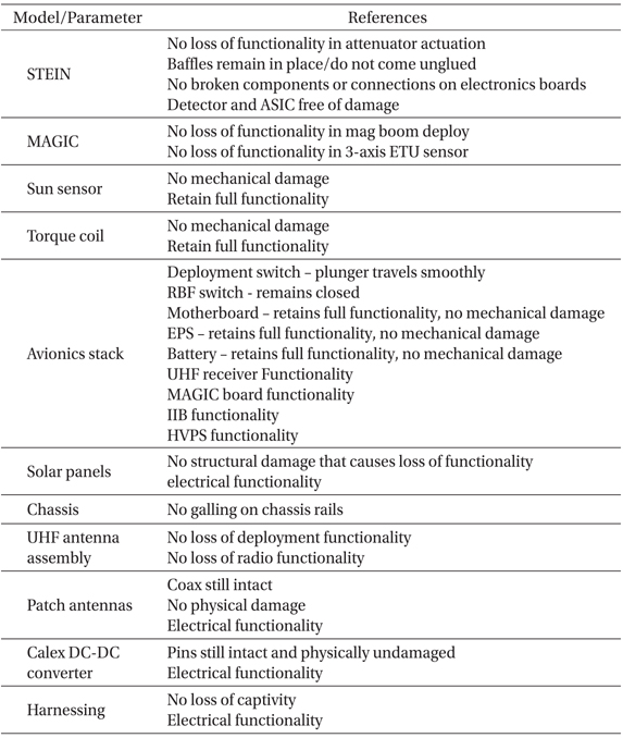
Total eight times of functional tests were conducted, before the thermal vacuum test, after an hour of each soak time, and after the thermal vacuum test. The functional test verifies the status of normal operation of each electrical and mechanical component in thermal cycle test based on Table 6, and examines the transformation of appearance that may occur during the thermal vacuum test through visual inspection, after the end of the test. Among the functional test items in Table 6, the injection test of MAGIC requires the disassembly of TRIO-CINEMA due to the instrument’s own characteristic. Therefore, injection test of MAGIC is excluded since vibration characteristics may change owing to the disassembly and re-assembly. Torque coil was also excluded from the functional test items due to the difficulty of measuring magnetic field. Functional test of solar panels and sun sensors were conducted after the end of the thermal vacuum test because of the absence of light source in the chamber. Injection test of UHF antenna also was conducted due to the narrow space inside of the shroud. Through the functional tests, such as the operation of the individual PCBs, change of battery voltage, and communication test using antenna, validate the normal operation within the high vacuum state and extreme temperature change.
[Table 6.] Functional test lists of thermal vacuum test.

Functional test lists of thermal vacuum test.
This paper describes thermal vacuum tests on the two flight models of TRIO-CINEMA. A monitoring system was established before the test, based on LabVIEW program. To solve the problem taking much time in cooling, the shroud is covered with MLI film and cooling changed into two modes of conduction and radiation through shroud modification. We could reduce about 20 % of cooling time. Based on the temperature change values of satellite surface between -13 ℃ and +31 ℃, which is thermal analysis result, this research demonstrated that the two flight models can meet the requirement of temperature by setting experiment temperature range between -20 ℃ and +35 ℃ in the newly developed chamber. The temperature, through which the experiments were carried out, has broader temperature condition than the thermal analysis results as a design margin. This paper has confirmed normal operation of the satellites in a situation that the satellites are exposed to lower temperature environment longer than the analysis results by providing prolonged cooling time. The current thermal vacuum test results have allowed undertaking the thermal vacuum test process of a satellite to be developed by Kyung Hee University.