The next generation small satellite-1 (NEXTSat-1) program has been kicked off in 2012, and it will be launched in 2016 for the science missions and the verification of space core technologies. The payloads for these science missions are the Instrument for the Study of Space Storms (ISSS) and NIR Imaging Spectrometer for Star formation history (NISS). The ISSS and the NISS have been developed by Korea Advanced Institute of Science and Technology (KAIST) and Korea Astronomy and Space science Institute (KASI) respectively. The ISSS detects plasma densities and particle fluxes of 10 MeV energy range near the Earth and the NISS uses spectrometer. In order to verify the spacecraft core technologies in the space, the total of 7 space core technologies (SCT) will be applied to the NEXTSat-1 for space verification and those are under development. Thus, the operation modes for the ISSS and the NISS for space science missions and 7 SCTs for technology missions are analyzed for the required operation time during the NEXTSat-1’s mission life time of 2 years. In this paper, the operational concept of the NEXTSat-1’s science missions as well as the verification of space core technologies are presented considering constraints of volume, mass, and power after launch.
The next generation small satellite-1 (NEXTSat-1) is one of the small satellite series weighing ~100 kg and 600 × 600 × 800 mm in dimension for the next generation standard platform (Shin 2013a). It will cover all the possible science and technology demonstration payloads considering constraints of mass and volume with a minimum design change (Shin 2013b). The NEXTSat-1’s mission orbit is not determined yet, because the launch vehicle for this program is under review (
The main objectives of ISSS are to detect the plasma and the space radiations using detectors and probes at the South Pole (
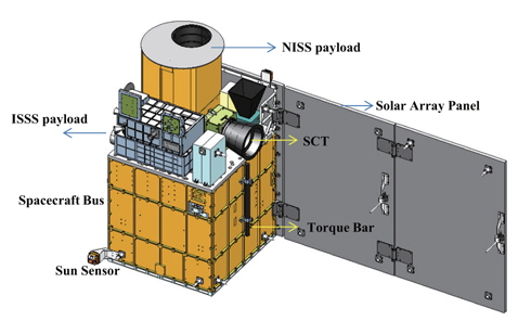
Thus, the NEXTSat-1 is currently under development in the phase of Development Model (DM) for functional tests of novel bus technologies and algorithms, which consists of the spacecraft bus, the science payloads, and the space core technologies as shown in Fig. 1.
Normally, the spacecraft bus is developed for supporting the science missions and technology verification of novel core technologies in the space. In order to comply with the top level requirements of the NEXTSat-1, the spacecraft not only performs the science missions with ISSS and NISS, but also conducts technology verification in the space such as the 3-dimensional mass memory (3DMM), the fiber optic gyro (FOG), the S-band Digital Transponder (SDT), the Star TRacker (STR), the On-Board Computer (OBC), the DC to DC converter (DC/DC converter), and the Space Data Recorder-10 (SDR-10). However, the NEXTSat-1 has a limited volume to produce power from the Sun in the space. Operational concept for the NEXTSat-1 should be considered to support the science missions with the ISSS and the NISS as well as the technology verification of 3DMM, FOG, SDT, STR, OBC, DC/DC converter and SDR-10 in the space. The NEXTSat-1 is to be operated in the low earth orbit about 700 km, thus the 100 minutes are required per an orbit. In other words, the maximum eclipse time is 36 minutes per an orbit which generates the lowest power during the sunlight. Thus, the operational concept shall be designed for proper operations and missions considering a duty cycle for each payload under those constraints such as power consumption and power generation through the solar array panels.
2.1 Tracking condition geometry
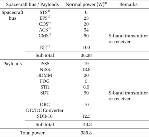
The first step for the operational concept is to survey and gather power consumption data for each unit of the NEXTSat-1, because the power consumption is a crucial parameter to make the proper duty cycle in an operational mode. Due to the limited power generation, we have tried to reduce power consumption in the design phase to give a flexibility in operational concept. Thus the power consumptions in the current design for each unit are shown in Table 1.
[Table 1.] Power consumption survey in spacecraft bus and payloads.

Power consumption survey in spacecraft bus and payloads.
3. OPERATIONAL MODE AND SCHEDULE
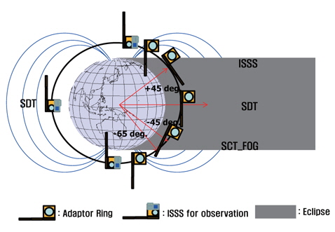
With the power consumptions described in Table 1, we have made the operational mode for each bus and payload to accomplish the science missions properly in the space and the space core technology verification. Basically, the ISSS only performs the science missions at the beginning of eclipse period for 25 minutes as shown in Fig. 2, which is drawn with the OMERE software, a freeware dedicated to space environment and radiation effects on electronic devices. In other words, the ISSS observes the space storms which occur when the solar activity is in the declining phase rather than the solar maximum (Sohn et al. 2012). During the sunlight just after escaping the eclipse, the space core technologies such as SDT will be verified as well as FOG at the time as depicted in Fig. 2.
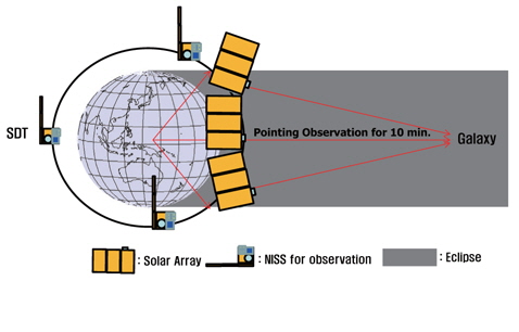
The mission of NISS which observes the star formation, is also performed in the eclipse period for 10 minutes for target object with step maneuvering as shown in Fig. 3.
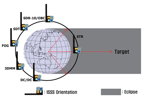
At the same time, STR and SDT payloads also perform the missions for space verification, which have a duty cycle of 10 minutes and 5 minutes, respectively. In addition, the other space core technologies, 3DMM and SDR-10/OBC, shall have independent orbits for space validation during the sunlight. Fig. 4 shows the operation sequence for 3DMM, SDR-10/OBC and DC/DC converter payloads.
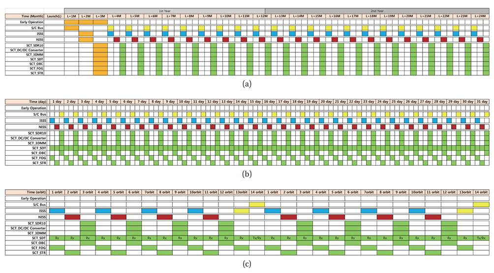
With Figs. 2-4, the operational schedules are planned based on yearly, monthly, and daily mission operations. Fig. 5 shows the overall operational plan for the science and space core technologies. In the early operational phase after launch, the Launch Early Operational Plan (LEOP) is prepared for 3 months to check the spacecraft bus and payloads as shown in Fig. 5a. Following that of LEOP, a normal operation sequence will be performed depending on the operational scenario until the last month.
More detailed operational schedule for monthly plan is shown in Fig. 5b. The ISSS and the NISS perform the science missions to accomplish the science objectives such as observing the space storms and star formation history, respectively. In addition, 7 space core technologies shall be verified for their functionalities and performances compared to requirements. However, consideration will be given to power consumptions because of the constraints of size and mass of the NEXTSat-1.
Moreover, the daily base operation mode has already been planned as shown in Fig. 5c. Because the NEXTSat-1 is operated in LEO about 700 km, the number of total revolution per day will be within 14 to 16 times. Thus, during the first orbit, the ISSS will perform the science mission with the SDT and the FOG at the same time. Then, the NISS will be followed by the next orbit with SDT and STR in the eclipse period about 30 minutes. After the operation of ISSS and NISS, the third orbit will be assigned to SDR-10, OBC, 3DMM, and SDT for space verification. Thereafter, the same operation sequence will be repeated for the successive orbits. Therefore, the ISSS will perform the observation of the plasma and space radiation, and the NISS will also perform the observation of star formation. And, the last orbit per day will be assigned to the download of the observed science data from the spacecraft to ground station (GS) using X-band transmitter with 16 Mbps baud rate.
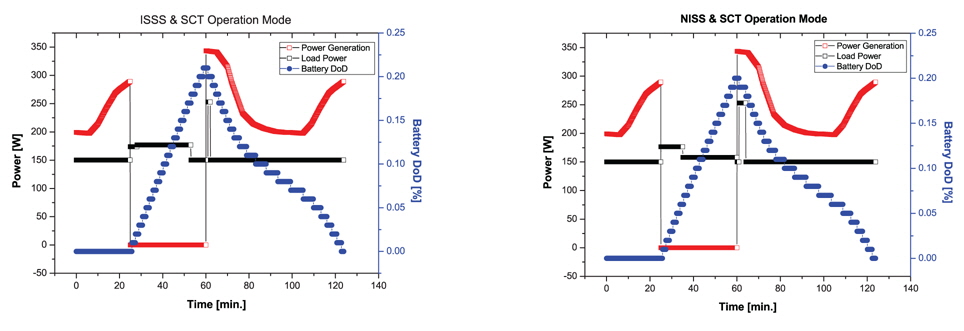
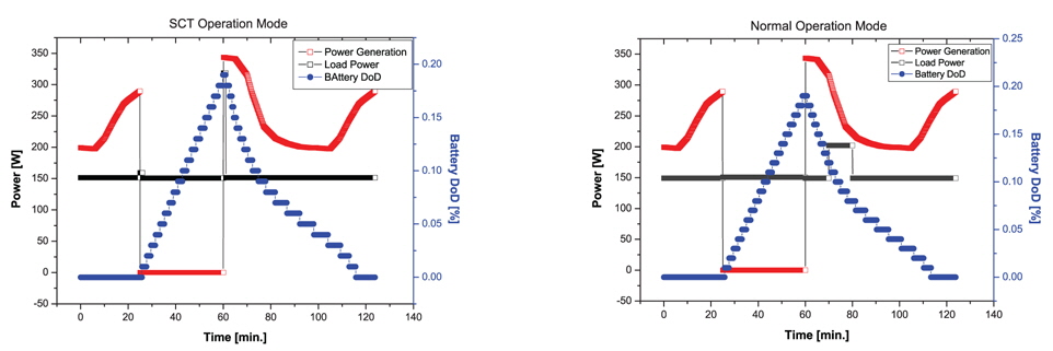
To verify the operational modes and the concepts which are described in Section 3, the power budget analysis was performed for the sunlight and the eclipse as along with the energy balance analysis to determine the solar array and battery capacity. The Interagency Operations Advisory Group (IOAG) had tried to communicate through relay communications at Mars via ultrahigh frequency (UHF) to explore the deep space (Edwards et al. 2011) with the concept of operations. The INTernational Gamma Ray Astrophysics Laboratory (INTEGRAL) has provided an overview of the mission operations concept to obtain the science data, and is dedicated to the fine spectroscopy (Dreger et al. 1999). In addition, the operational mode was considered with the space radiation effects on FPGA (Shin et al. 2013). With the operational mode and concept, the required battery capacity and solar array capacity are calculated by the consumption of the electrical energy. As mentioned in Section 1, the NEXTSat-1 will be the LEO of about 700 km altitude. During the sunlight of minimum 66 minutes, the required power should be generated from the solar array panel, which goes to the spacecraft bus and the payloads. The remaining power recharges the battery to supply the electrical power in the eclipse period. Therefore, the battery and solar array capacities shall be properly balanced.
Triple junction solar cells of GaAs technology and lithium-ion cells for recharging electrical energy are applied in this study. Fig. 6a shows the results of energy balance analysis at the end of life time considering the solar array temperature, the degradation factors, the wire loss, and the conversion efficiency regarding the space core technologies for space verification, which performed the on orbit test with 10% duty cycle. And also, the battery efficiency for charging and discharging is considered in this power analysis. As you may know, the battery was fully charged after the eclipse period. It means that the energy is balanced with the consumption and saving. Fig 7b represents the normal Ground Station (GS) contact mode for commanding and receiving the status of health data from the spacecraft using the S-band transmitter and receiver.
Through Table 1 which represents the power consumptions for each unit, the total power consumptions in the sunlight and in the eclipse period are calculated. The total power consumption is about 150 W in the sunlight during mission operation, and is about 150 W in the eclipse period with science and space core technologies missions. Therefore, the required power from the solar array panels is about 150 W during the sunlight. And also, the required battery capacity for mission operation in the eclipse period is 16.8 Ah with a margin of 10%. However, the battery depth of discharge during the mission operation will be within 19%.
There are three main missions for the NEXTSat-1 program such as ISSS, NISS, and SCT for space verification. In normal operation, the ISSS and the NISS for the science missions will have 4 orbits per day and also the SCT payloads will have the same chances of observation per day. However, particle detectors shall have a priority after solar events such as micro-bust, dusk-side relative electron, positive storm, and negative storm at the South Pole in the eclipse period.
Through the operational plan and power consumption, the operational schedules are planned as shown in Fig. 4, and the system requirements in terms of solar array size and battery capacity for mission operation during the sunlight and the eclipse period are obtained. Therefore, the solar array size and the battery capacity are assigned to the mechanics for an optimal spacecraft design. Normally, the solar array or battery should have a priority in design because it is a factor for a life time determination.
In this study, the operational plan for the NEXTSat-1 program is reported presenting the overall mission schedule on a yearly and daily basis. Since the design of the full spacecraft system is currently in progress, some parameters can be modified and the operational concept for the NEXTSat-1 will also be modified depending on the design progress.