Activated carbon nanofibers (ACNF) were prepared from polyacrylonitrile (PAN)-based nanofibers using CO2 activation methods with varying activation process times. The surface and structural characteristics of the ACNF were observed by scanning electron microscopy and X-ray diffraction, respectively. N2 adsorption isotherm characteristics at 77 K were confirmed by Brunauer-Emmett-Teller and Dubinin-Radushkevich equations. As experimental results, many holes or cavernous structures were found on the fiber surfaces after the CO2 activation as confirmed by scanning electron microscopy analysis. Specific surface areas and pore volumes of the prepared ACNFs were enhanced within a range of 10 to 30 min of activation times. Performance of the porous PAN-based nanofibers as an electrode for electrical double layer capacitors was evaluated in terms of the activation conditions.
Electrochemical energy storage and conversion devices play an important role in modern society, with applications in accommodations, portable devices, transportation, the military and space exploration [1,2]. A supercapacitor is a kind of novel device that stores electrical energy in an electrode/electrolyte interface [3]. In a supercapacitor, an electrostatic attraction at the electrode/ electrolyte double-layer interface results in the accumulation of charges and stored energy. Supercapacitors are very useful for large-scale portable electronic systems and automotive applications, due to their high power density, excellent reversibility, and long cycle life.
In recent years, efforts to develop better supercapacitor electrode materials have gained considerable attention [4]. Carbon materials are widely used for supercapacitor electrodes because of their relatively low cost, versatile existing forms, large specific surface area, good electric conductivity, and excellent chemical stability [5]. Generally, a highly developed surface area and porosity are necessary for carbon electrodes to obtain high specific capacitance. For this reason, activated carbons (ACs) have been widely adopted as electrode materials for supercapacitors.
ACs have attracted wide interest as the electrode material for energy storage in supercapacitors due to their very high specific surface area, simple processability and low costs. Chemical [5,6] and physical [5] methods of carbon activation are well known and allow the production of materials which are well defined in terms of specific surface area and pore size distribution. When fibrous precursors are used, activated carbon fibers are obtained which exhibit high adsorption/desorption rates and narrow pore size distribution [5,6].
Activated carbon nanofibers (ACNFs) are a relatively modern form of porous carbon material with a number of significant advantages over the more traditional powder or granular forms [7]. Advantages include high adsorption and desorption rates, thanks to the smaller fiber diameter and hence very low diffusion limitations, great adsorption capacities at low concentrations of adsorbates, and excellent flexibility [3]. Using fibrous materials is additionally profitable from the construction point of view.
CNFs have been receiving increasing attention because of their high length-to-diameter ratio and their potential applications in composite materials [8], filters [9], gas sensors [10], anode materials for rechargeable batteries [11], supercapacitors [3], bottom-up assembly in nanoelectronics, and etc. Among the materials used in the preparation of CNFs, polyacrylonitrile (PAN) and its copolymers are recognized as the most promising precursors [5,6,10,12]. In general, a number of methods are available for the preparation of polymeric nanofibers, though the one most widely used is electrospinning.
Electrospinning of polymers is a very successful method for preparing fibers with nanometer sized diameters. The fibers can be electrospun in the form of yarn, aligned fibrous arrays, or webs. In particular, the electrospinning of PAN, followed by stabilization and carbonization, results in CNFs. PAN is often selected as the precursor because of its advantages, including good spinnability in solution and its relatively high carbon yield [13].
The production of ACNFs involves spinning of the precursor fiber, stabilization of the precursor chemical structure under an oxidizing atmosphere, carbonization under an inert gas, and finally activation under an activating gas, such as CO2 or H2O vapor (physical activation), or an oxidizing reagent such as KOH or ZnCl2 (chemical activation) [5,6].
Chemical or physical activation of PAN-based carbon materials has been already reported in the literature. The physical activation method involves carbonization of the raw material and its subsequent activation at high temperature in CO2 or H2O vapor. The chemical activation method involves the carbonization of a raw material previously impregnated with a chemical agent.
In the case of chemical activation by ZnCl2 or KOH, many by-products remain in the fibers. These activating agents are more expensive, and an additional washing stage is also necessary. Therefore, physical activation with CO2 or H2O is the usual procedure to obtain ACNFs. It is known that physical activation using carbon dioxide results in a more homogeneous development of porosity within the carbon fibers than steam.
In the present study, we tried to develop activated carbons with a large specific surface area and optimal pore structures from PAN-based ACNFs through CO2 activation. Various analytical techniques were utilized to investigate the morphology and material properties of the precursors and final nanofibers. Finally, an exploration of the properties of the ACNFs demonstrated the increased porosity and total surface area of the CNFs.
PAN (Mw = 150 000) purchased from Sigma Aldrich Chemical Co. was used as the spinnable polymer for all precursor solutions. PAN precursor solutions of 10 wt% were prepared in N,N-dimethylformamide to obtain CNF materials denominated as PAN. After gentle stirring at room temperature for 7 h, these solutions were loaded into a 10 mL polypropylene syringe equipped with a stainless steel needle that was connected to the anode of a high voltage power supply. The conditions employed for electrospinning were 15 kV applied voltage, 15 cm tip-to-collector distance, and a flow rate of 0.5 mL/h. A grounded stainless steel roll wrapped with aluminum foil was employed as the collector. The nanofibers were stabilized in air at 280℃ and carbonized at 1000℃ in N2.
Activation of the CNFs was performed using CO2 as the physical reagent. CO2 activation was performed in the same quartz tube as the carbonization. The CNFs were heated (5℃/ min) to the required reaction temperature (1000℃) under N2 (500 mL/min), before the N2 was switched to CO2 (500 mL/min) for various activation times, from 10 min to 40 min; the resulting samples were designated ACNF-10 to ACNF-40. The samples were allowed to cool under N2 (500 mL/min).
The nitrogen adsorption isotherms of the CNFs and ACNFs were measured with BELSORP-max (BEL JAPAN, Japan) at liquid nitrogen temperature. All samples were degassed at 300℃ for 6 h prior to measurement. The specific surface area was calculated in the relative pressure interval of 0.04-0.2 using the Brunauer-Emmett-Teller method [14]. Micropore size was calculated by the Dubinin-Radushkevich equation from adsorption curves [15,16]. The d002 space differences between pure CNFs and ACNFs were determined using a wide-angle X-ray diffractometer (WAXRD), employing a Rigaku SmartLab X-ray diffractor with a customized auto-mount and a Cu Kα radiation source. Diffraction patterns were collected within the diffraction angles from 10° to 90° with a speed of 2°/min. The morphologies of CNF, ACNF-10, ACNF-20, ACNF-30, and ACNF-40 were explored using a field emission scanning electron microscope (JSM 6701-F, JEOL, Japan). To reduce charging during scanning electron microscopy (SEM) imaging, the samples were first placed on a sample holder and coated with platinum.
2.4. Electrochemical measurements
Electrodes were prepared by mixing 80 wt% of carbon source, 10 wt% of conductive agents (carbon black), 10 wt% of carboxymethyl cellulose and styrene-butadiene rubber binder dispersed in isopropanol. The slurries were rolled into a membrane and then pressed onto Al mesh current collectors. Thereafter, the electrodes were dried at 120℃ for 24 h in an oven. A two-electrode configuration was used to measure electrochemical performance. Working electrodes were fabricated by pressing the ACNF-coated film between two circular pieces of Al mesh. An organic electrolyte (1 M (C2H5)4NBF4/propylene carbonate) was used.
The fifth cycle of galvanostatic charge/discharge was used to evaluate the electrochemical performance of the samples. The specific capacitance was calculated according to the charge/discharge tests based on the following equation:

where
3.1. Surface morphology analysis
The external pore structure of the ACNFs was observed by SEM, and SEM images of all the ACNFs sample types are shown in Fig. 1, in order by activation process time. Fig. 1 shows SEM images of CNF and its activated forms. The pores and cracks that developed on the surface due to activation can be seen in Figs. 1b-e. The average pore size of ACNF-10, ACNF- 20, ACNF-30, and ACNF-40 was increased by activation. Fig. 2a shows the average diameter of the CNFs, which was around 600-700 nm. The diameter of an ACNF decreased with increasing activation time. It was found that the diameter of the fibers decreased to around 500-700 nm as a result of surface oxidation during the CO2 activation (40 min).
3.2. Textural properties and pore structure
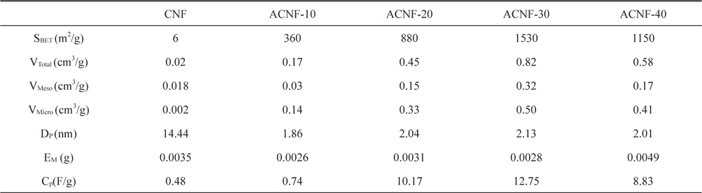
The specific surface area and pore structures of the activated carbons nanofibers before and after activation are shown in Table 1. The specific surface area of the as-received carbon fibers (6 m2/g) increased with CO2 activation (to 1530 m2/g). Based on the literature data [5,17] for PAN-based CNFs, it was expected that the specific surface area would increase with burn-off. However, when the activation time was 40 min, a significant decrease of specific surface area was observed, dropping to 1150 m2/g. The textural properties showed the highest result with ACNF 30 min and then deceased in all highly activated samples. The ACNF-30 sample showed better-developed mesopores than the ACNF-20 and ACNF-40 samples. This means that a moderate activation time results in large pore size.
[Table 1.] Textural properties and specific capacitance of ACNFs as a function of activation time

Textural properties and specific capacitance of ACNFs as a function of activation time
Based on the SEM characterization, this trend may be explained as follows.
1) During the initial increase of activation time, micropores and/or mesopores with small pore diameters formed first as a result of the reaction between CO2 and carbon. With increasing activation time, the quantity of the surface pores increased, leading to increased specific surface areas.
2) However, with further increasing activation time, the pores that developed in the initial stage started to deepen, enlarge, and perhaps merge, resulting in the observed decrease in the specific surface area and the increase in the average pore width.
ACNFs produced from nanofiber webs using CO2 activation can be crystallographically characterized by means of XRD. The interlayer spacing, d002 was determined using the following Bragg equation:

where λ is the X-ray wavelength, and θ is the scattering angle for the peak position.
The XRD analysis was performed with CuKα with a wavelength of 0.154 nm. The values of d002 of the prepared ACNFs are given in Fig. 3. It is well-known that the oxidation behaviors of carbonaceous materials preferably occur in the amorphous region and graphite edges. If carbon atoms in the amorphous regions of the carbonized fibers are removed first, the overall crystallinity of the carbonized fibers can be increased due to the reduction of a portion of the amorphous regions, resulting in a decrease in the d002 of activated fibers. There will be an expected increase of d002, if carbon atoms in graphite edges are removed after the oxidation of the amorphous regions. Therefore, considering that the sample carbonized fibers here were observed to decrease in d002 at 30 min, it could be expected that the overall crystallinity of the carbonized fibers would increase due to the reduction of a portion of the amorphous region, resulting in the increase in specific surface area of the ACNFs. There was an expected increase of d002 after 40 min. Consequently, carbon atoms at the edges of graphite had been oxidized as expected. Thus the d002 values were slightly increased with a decrease in the specific surface area of all samples.
3.4. Electrochemical characterizations
The electrochemical properties of the ACNF electrodes including galvanostatic charge/discharge were studied with an electrolyte of propylene carbonate solution. Fig. 4a shows the typical galvanostatic charge/discharge curves of the specific capacitance in relation to current density for ACNF electrodes prepared with various activation times. At a current density of 2 mA/g, the specific capacitance increased with increasing mesoporosity. Sample ACNF-30, with the highest mesoporosity, had the highest specific capacitance of 12.7 F/g.
In this work, PAN-based ACNFs were prepared with different activation times in order to produce ACNFs with high specific surface areas and mesopore-rich pore structure. As a function of activation time, the specific surface area increased up to ACNF-30 min and then decreased, and mesopore volume showed a similar trend as well. The ACNF-30 sample showed the highest specific surface area because it had the highest mesoporosity.