Electrical resistance change measurements were performed, to detect fatigue damage of a quasi-isotropic CFRP and cross-ply CFRP laminates. A four-probe method was used to measure the exact electrical resistance change. A three-probe method was used to measure the electrical contact resistance change, during long cyclic loading. The specimen side surface was observed using a video-microscope to detect damage. The measured electrical resistance changes were compared with the observed damage. The results of this study show that the electrical resistance increase of the quasi-isotropic laminate was caused by a delamination crack between ±45° plies. Matrix cracking caused a small electrical resistance increase of the cross-ply laminate, but the decreased electrical resistance caused by the shear-plastic deformation impedes matrix-cracking detection.
The electrical resistance change of carbon fiber reinforced polymer (CFRP) composites is useful information to monitor damage initiation. Many researchers have adopted the electrical resistance change method to detect several kinds of damage in CFRP composites [1-23].
Schulte et al. [1] measured electrical resistance changes of coupon specimens during tensile tests using a two-probe method: two electrical probes are made at both ends of the specimen, to apply electric current, and to measure electric voltage change. Wang and Chung [4] adopted a four-probe method, to cancel the electrical contact resistance at the specimen electrodes. The outer couple of electrodes is used to apply electric current. The inner couple of electrodes are used to measure electrical voltage change. Irving et al. [6] and Seo et al. [7] used the electrical resistance change method to detect fatigue damage in a unidirectional CFRP, and in a cross-ply CFRP. De Baere et al. [15] used the electrical resistance method for fatigue damage detection in woven fabric CFRP composites.
An earlier report in the literature described cyclic loading tests performed with low applied strain, to prevent fatigue damage in CFRP specimens [24]. Cyclic loading tests of the quasi-isotropic laminate with low applied strain showed a decrease of electrical resistance in the specimens. The decreased electrical resistance was caused by the shear-plastic deformation of the ±45° plies: plastic deformation of the ±45° plies during cyclic loading causes shrinkage of thickness; then the thickness reduction increases electrical conductance in the thickness direction, in the same way that a dent does [23].
In this study, cyclic loading tests were performed at a higher applied strain, to elucidate fatigue damage in the quasi-isotropic laminate and the cross-ply laminate specimens, using electrical resistance changes. Specimen side surfaces were carefully observed, using a video-microscope. The electrical resistance changes were measured using the four-probe method. The measured electrical resistance changes were compared with the observed damage. Finite Element Method (FEM) analyses of the electric current density were performed, to investigate the relation between the observed damage and the electrical resistance changes.
2.1 Specimens and fatigue test method
The material used in the experiments is a unidirectional prepreg sheet (PYROFIL#380). The stacking sequences are quasi-isotropic [0/45/-45/90]S and cross-ply [02/902]S. Plates of 250 mm length, 150 mm width, and 1.7 mm thickness were produced using an autoclave. The pre-cure conditions were 85℃ × 2 hr. The main curing conditions were 135℃ × 3 hr under 0.7 MPa pressure. After curing, the fiber volume fraction
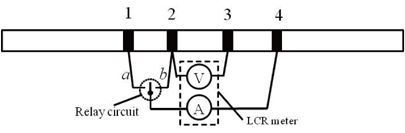
To measure the electrical resistance of the specimen, the four-probe method was adopted, and an LCR meter (3522; Hioki E. E. Corp., Japan) was used. For measurements, alternating current of 450 Hz of 30 mA was applied. The impedance using the alternating current was measured. Because the phase angle of the measured impedances was zero, the measured impedance was regarded as an electrical resistance in this study. To measure the electrical contact resistance at the electrode, a three-probe method was applied. The difference between the four-probe method and the three-probe method is described in section 2.2 and the reference [24].
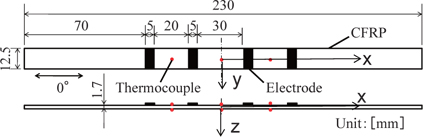
K-type thermocouples were used to measure specimen temperatures. At the middle between the electrodes, the K-type thermocouples were mounted in the positions shown by dots in Fig. 1. The variation of the measured temperature of the six points was kept within ±1 ℃ during the cyclic loading test. Because the temperature effect is extremely small, temperature change compensation was not performed.
For the cyclic loading test, a closed-loop hydrostatic servomaterial- testing machine was used. Tension–tension cyclic loading tests of stress ratio
2.2 Four-probe method, and three probe method
The four-probe method and the three-probe method are presented in Fig. 2. When the outer couple of electrodes (#1 and #4) were used to apply electric current, and the inner couple of electrodes (#2 and #3) were used to measure the voltage change (the relay circuit is switched to line “
In this study, the electrical resistance (
All of the measured electric resistance changeΔ
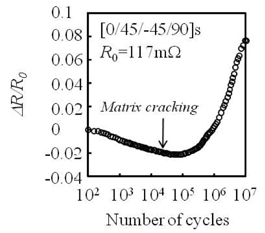
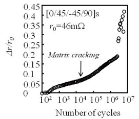
Figure 3 shows the experimentally obtained results of electrical resistance change, during cyclic loading of the quasi-isotropic specimen. The abscissa shows the number of cycles. The ordinate shows the measured electric resistance change using the four-probe method. Similar to the electrical resistance change of the low applied strain in the previous paper [24], the electrical resistance decreases with the increase of the number of cycles, up to 4×10⁴ cycles. Beyond 4×10⁴ cycles, however, the electrical resistance starts to increase.
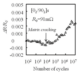
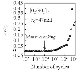
Figure 4 shows the experimentally obtained results of electrical resistance change, during cyclic loading of the cross-ply specimen. Similar to the electrical resistance change of the low applied strain in the previous paper [24], the electrical resistance is almost constant with the increase of the number of cycles, before 1×10⁴ cycles. After 1×10⁴ cycles, the electrical resistance starts to increase.
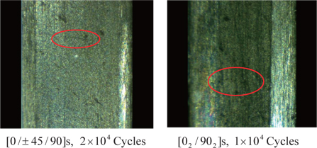
Figure 5 shows the specimen side surface observed at the cycles of the damage initiation. As shown in the circles in the figure, a matrix crack is observed in the 90°-ply. As portrayed in Fig. 4, the matrix cracking seems to start at the increase of electrical resistance of the cross-ply laminate. In contrast, no electrical resistance increase of the quasi-isotropic laminate is observed at 2×10⁴ cycles in Fig. 3.
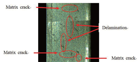
Figure 6 presents observations of the specimen side surface of the quasi-isotropic laminate at the number of cycles of 4×10⁴. The delamination cracks and matrix cracks are visible in Fig. 6, as shown in circles. As depicted in Fig. 3, the electrical resistance of the quasi-isotropic laminate increases from approximately 4×10⁴ cycles. Therefore, the electrical resistance of the quasi-isotropic laminate indicates delamination cracking.
The magnitude of the electrical resistance change between the quasi-isotropic laminate and the cross-ply laminate can be compared, as shown in Figs. 3 and 4. The initial decrease of the electrical resistance change ratio of the quasi-isotropic laminate (in Fig. 3) comes from the decrease of thickness caused by the in-plane shear plastic deformation in the ±45°-plies during tensile loading, as shown in reference [24]. The tensile stress applied in the quasi-isotropic laminate, and the tensile deformation of ±45°-plies includes in-plane shear deformation that has large plastic deformation. For the cross-ply laminate in Fig. 4, the laminate has no angle plies, and that means the laminate has no in-plane shear plastic deformation. This caused no change of Δ
Because the reference resistances
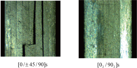
Figure 7 shows the specimen side surface after the number of cycles of 107. For the quasi-isotropic specimen, large delamination cracks are visible. For the cross-ply laminate, many matrix cracks are observed, but no delamination crack is observed. This difference is caused by the difference of applied stress. As the applied cyclic strain of the two different laminates was set to the same value, the applied stresses were different between the two laminates. As the cross-ply includes four of the 0°-plies, the ultimate fracture strength of the cross-ply is higher than that of the quasi-isotropic laminates. This caused the delamination of the quasi-isotropic laminates at this applied strain, and no delamination in the cross-ply laminates. This difference of the damage mechanism also caused the difference of the electrical resistance changes between the quasi-isotropic specimen and the cross-ply specimen. The delamination crack caused shut down of the electric current path between the ±45°-plies in the quasi-isotropic laminates, and the absence of delamination in the cross-ply laminates caused only small electrical resistance increase, caused by the matrix cracking.
To investigate the effect of the damage mechanism on the electrical resistance changes, FEM analyses of the electric current density of both types of specimens were performed, using commercially available FEM code ANSYS ver.12. Three-dimensional FEM analyses were conducted, using a SOLID 226 element of 20 nodes. The material properties used for the FEM analyses were referred from an earlier report [8]. The total number of elements used for the analyses was 7,360. The applied current was 30 mA, which is the same as the actual specimen. Fig. 8 shows the contour plot of the electric current density of the cross section of the specimen middle point: for both specimens, most of the electric current flows in the top surface 0°-ply. In the quasi-isotropic laminate, however, a considerable amount of electric current flows in the angle plies (the second and the third ply). In these angle plies, electric current flows in the fiber direction (+45° or -45° in each ply). The current flows in the thickness direction at the specimen end, and flows in the fiber direction in the other ply, as described in an earlier report in the literature [24]. The large electric current in the thickness direction is impeded by the delamination crack. For that reason, the delamination crack has a strong effect on the electrical resistance change in the quasi-isotropic laminate.
Figures 9 and 10 show the contact-resistance change at the electrode during cyclic loading, measured using the three-probe method. The reference resistances (
[Fig. 10.] Change of the contact electrode resistance during cyclic loading of a cross-ply laminate.
In actual laminates, angle plies are almost always included. Therefore, when the electrodes are made on the laminate surface, the contact resistance of the actual laminates increases. The four-probe method is indispensable for a long-term monitoring system.
This report described cyclic loading tests of CFRP laminates of a quasi-isotropic laminate and a cross-ply laminate, under high applied strain. Fatigue damage of matrix cracking and delamination cracking were observed at the specimen side surface, using a video-microscope. Electrical resistance changes of the specimens were measured, using the four-probe method. Contact resistance changes were also measured, using the three-probe method. The following results were obtained.
(1) For a quasi-isotropic laminate, matrix cracking in the 90°-ply is undetectable. The in-plane shear plastic deformation of the ±45°-plies caused a significant decrease of the electrical resistance, and this makes it quite difficult to detect the initiation of matrix cracking. (2) Delamination cracking can be detected by the electrical resistance change for a quasi-isotropic laminate. The delamination crack shut down the electric current path between the ±45°-plies, and this can be detected by the significant increase of the electrical resistance change ratio. (3) For a cross-ply laminate, matrix cracking is detectable, using the electrical resistance change method. However, the magnitude of the electrical resistance change of the cross-ply laminate is extremely small, compared with the electrical resistance change caused by delamination cracking in the quasi-isotropic laminate. The electric current in the 90°-ply is very small, compared with that in the 0 °-ply and ±45°-plies. This caused small electrical resistance change, by the matrix cracking of the cross-ply laminate. As delamination cracking does not occur in the applied strain level for the cross-ply laminate, large electrical resistance increase was not observed in the present study. (4) The contact resistance at the electrodes increases for the quasi-isotropic laminate from the beginning, because of the in-plane shear-plastic deformation of the ±45°-plies. For the ±45°-plies, applied tensile cyclic strain caused plastic deformation, because of the in-plane shear stress. For the quasi-isotropic laminate, this caused increase of the contact resistance at the electrode.


![Electrical resistance change during cyclic loading of [0/±45/90]s.](http://oak.go.kr/repository/journal/13493/HGJHC0_2013_v14n4_350_f003.jpg)
![Electrical resistance change during cyclic loading of [02/902]s.](http://oak.go.kr/repository/journal/13493/HGJHC0_2013_v14n4_350_f004.jpg)
![Delamination initiation of [0/±45/90]s.](http://oak.go.kr/repository/journal/13493/HGJHC0_2013_v14n4_350_f006.jpg)