With scientific and technological advancements, many countries or organizations are carrying out extensive research on space and the Moon. The Moon, Earth’s natural satellite, has re-emerged as the focus of space research recently, because of its abundant natural resources, and high potential as a future territory. The Korea Aerospace Research Institute (KARI) is planning to launch a lunar exploration module by 2025, and has already proceeded with a preliminary study on a potential lunar module.
In the overall design of a lunar lander, the analysis of the touchdown dynamics during the landing stage is an important task, and the design of a landing system that can absorb the high landing impact energy is indispensable, for guaranteeing the stability and safety of the lunar module, and to protect the devices inside it. In the 1950s, mission flights in the Solar System were started. The use of a parachute or a balloon was considered, to reduce the landing velocity and impact between the lunar module and the lunar surface. But neither of these methods was effective. An aluminum honeycomb damper was not used until the late 1960s. The honeycomb damper was researched, to satisfy the strict requirements of spacecraft design. Apollo 11 first successfully landed on the lunar surface in July, 1969 [1]. Since the 1980s, the aluminum honeycomb shock absorber has been widely used in the aerospace industry.
Analysis study of the touchdown dynamic modeling and simulation of a lunar lander vehicle received great interest, and its touchdown stability was investigated [2, 3]. In this paper, the 1/6 model of a lunar module with the aluminum honeycomb shock absorber, and the lunar surface, are both constructed in ADAMSTM. The modeling method of the aluminum honeycomb damper and the lunar surface has been investigated. The landing stability of the lunar module on level and non-level surfaces is calculated. From the simulations, the proper method for modeling the damper and the lunar surface is investigated, and the landing stability of a 1/6 lunar module is presented.
2.1 Preliminary design of a lunar module
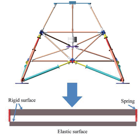
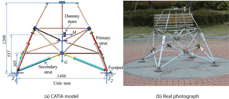
KARI made a preliminary design of a lunar module that is to land on the Moon. Its total mass was 250 kg. For testing, the 1/6 lunar module was considered in terms of mass, because the Moon’s gravity is one-sixth that of Earth. Fig. 1 shows the 1/6 lunar module, which consists of a truss structure and a dummy mass. The truss structure has four tri-pod legs. Each leg has one primary strut and two secondary struts to absorb shock energy. A dummy mass represents payloads, such as the electronic system, fuel, and guidance system.
This study investigates the landing stability of the 1/6 lunar module under the Earth’s gravity. First, the simple equation for an overturn was considered. Second, ADAMSTM was used to solve the multi-body dynamics of the landing of the 1/6 lunar module. A CAD model constructed in CATIA was imported into ADAMSTM, for use in simulations.
2.2 Theoretical landing stability
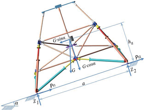
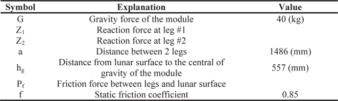
Fig. 2 shows the calculation of the tip-over angle of the 1/6 lunar module. Table 1 provides the definition of the symbols used in Fig. 2. Equilibrium equations can be derived for the configuration shown in Fig. 2.
[Table 1.] Definition of parameters and dimensions defined in Fig. 2

Definition of parameters and dimensions defined in Fig. 2
From the moment equilibrium at leg #1:

The module loses stability, when the reaction force Z2 = 0, so Eq. 1 becomes:

Then, the condition of module stability can be derived:

Also, the glide condition of the module can be derived:

By considering the parameters
2.3 Aluminum honeycomb shock absorber
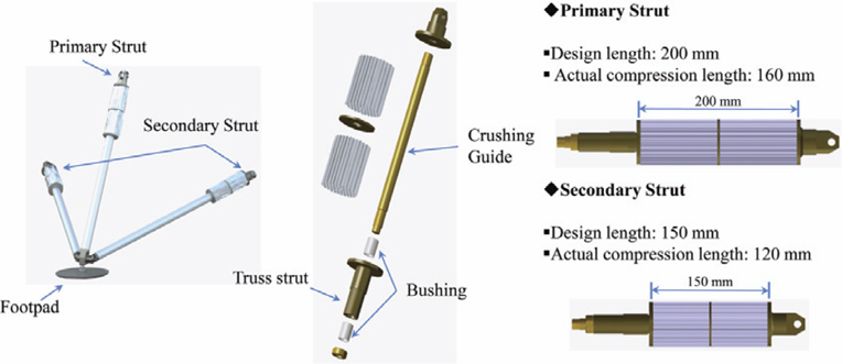
In the design of a lunar module, the landing gear system is considered to be one of the most important components. The landing gear must absorb the impact energy as much as possible, to protect the payloads, when the lunar module touches down on the lunar surface. Historically, several shock absorbers were invented, tested, and used for lunar modules: Ranger 4 in 1962 used a lunar capsule covered with a balsawood impact-limiter; Ranger 9 in 1965 consisted of a hexagonal aluminum frame, where the propulsion and power units were mounted; and Luna 8 in 1965 used an airbag [4]. However, for landing missions that carry human(s) to the Moon, energy absorbers should be designed to achieve a soft landing. The landing module needs to decelerate to a reasonable velocity, before hitting the Moon. While the balloon mechanism that was used for the landing on Mars is interesting and thought provoking, a parachute cannot be used for landing on the Moon, because the Moon’s atmosphere is very thin. Therefore, to overcome this limitation, an aluminum honeycomb shock absorber was considered a good solution. Apollo 11, the first spacecraft that brought men to land on the Moon, and returned them to Earth successfully [1], used an aluminum honeycomb shock absorber. Consequently, an aluminum honeycomb shock absorber was adopted for the present 1/6 lunar module. Fig. 3 shows the details of the landing gear, which is comprised of one primary strut, two secondary struts supporting the primary strut, and one footpad.
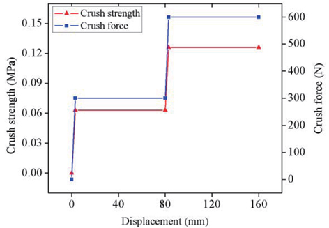
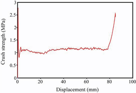
In addition to the analysis of the landing stability of the 1/6 lunar module, an analysis of the aluminum honeycomb shock absorber was carried out, for its characterization. Fig. 4 shows the crush test results of a developed aluminum honeycomb shock absorber. They revealed that 80% of the total length was used for energy absorption, and that the compression force was constant, after the initial stage of compression.
The shock absorber has two honeycombs of different crush strengths: the honeycomb of the first stage has small crush strength, and that of the second stage has large crush strength. The main reason for using the two-honeycomb design is that it can reduce the peak acceleration, as well as absorb the whole impact energy. The honeycomb with the small crush strength can absorb the impact energy at the moment of touchdown, reduce the peak acceleration, and protect important payloads. Then, the honeycomb with the high crush strength can absorb the whole impact energy. Transition from the first stage to the second stage places artificial shock on the lunar module. To avoid this, the ratio of the crush strengths between the first and second stages should be minimized.
Fig. 5 shows the assumed crush strength (force) versus displacement relation, for use in simulations. The assumed crush force of the aluminum honeycomb shock absorbers was roughly approximated by doing several simulation landings of a 10 degree tilted lunar module for two landing modes (1-2-1 and 2-2, explained later), at different crush forces, as given in Table 2. The main condition is that the two aluminum honeycombs absorb the entire landing energy.
[Table 2.] Different types of aluminum honeycomb damper
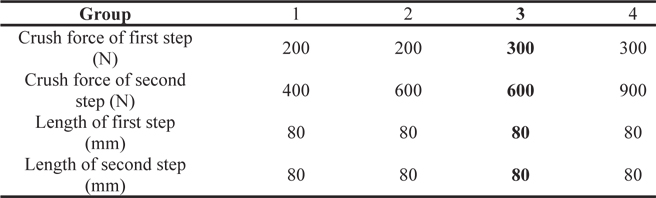
Different types of aluminum honeycomb damper
The simulation results revealed that the lunar module can land safely on the lunar surface, with the specification of shock absorbers in group 3 listed in Table 2. In the primary struts, an aluminum honeycomb shock absorber consists of two compression stages during the energy shock absorption period: the first stage with soft crush strength of 300N and length of 80mm, and the second one with hard crush strength of 600N and length of 80mm. The area of the aluminum absorber in the preliminary design was 70 × 68 mm2.
The surface properties of the Moon affect the design of a lunar module; in particular, the design of the landing gear. Topographical and soil-properties of the Moon are available in the references on the lunar surface [5, 6]. Fig. 6 shows the slope profile, protuberance, and modulus of the lunar surface. The topographical features consist of a mean surface slope of 60 or less, and an effective slope of 120 or less, including the effects of depressions or protuberances, and footpad penetration. The statistical description used most extensively was based on the topographical data from the Lunar Orbiter photograph of the most severe Apollo landing site.
Based on Apollo’s experiment data, the modulus of subgrade reaction of the lunar surface was investigated, by using 776 analyses of boot prints (40% analyses from Apollo 16). In the analyses, the area of applied load was 12.5cm × 3cm, and the applied load per unit area was
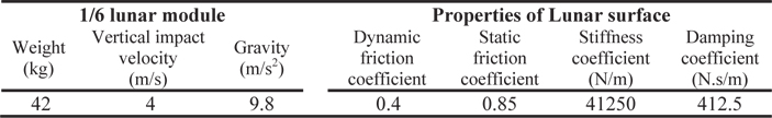
In this research, two types of lunar surfaces were considered in lunar surface simulations: the rigid surface, and the elastic surface. Fig. 7 shows the two types of lunar surfaces, along with the ADAMS model of the 1/6 lunar module. Even though a rigid surface does not reflect the actual property of the lunar surface, it can however serve as a reference. An elastic surface is two rigid surfaces connected by four springs.
Table 3 lists the specifications of the 1/6 lunar module, and the properties of the lunar surface. Based on the conditions, the spring constant of the elastic surface was 41250/4=10312.5 N/m. The lunar module constructed in ADAMSTM was composed of nearly 720 rigid bodies, and many constraints, such as translational joints, spherical joints, fixed joints, and revolute joints, were placed on them.
[Table 3.] Specification of 1/6 lunar module, and properties of lunar surface

Specification of 1/6 lunar module, and properties of lunar surface
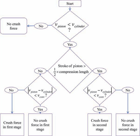
Three kinds of damper models were considered, to investigate the behavior of the struts: a rigid damper, a viscous damper, and an aluminum honeycomb damper. The rigid damper means that the strut does not have any damper, which was considered as a reference solution, like the rigid lunar surface. The viscous damper is a simple damper, which has a spring and a viscous damper, whose properties are listed in Table 3. To implement the aluminum honeycomb damper, an algorithm was invented, using Sforce and Step functions. Fig. 8 shows the flow chart the algorithm, and Table 4 lists one ADAMS example.
[Table 4.] An example of aluminum honeycomb damper modeling with the flow chart in Fig. 8
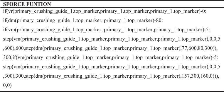
An example of aluminum honeycomb damper modeling with the flow chart in Fig. 8
Basically, a landing gear consists of two main parts: the lower part, which impacts with the surface, and the upper part, which is able to absorb shock, to protect equipment. The upper and lower parts of a landing gear strut were considered in the algorithm as a cylinder and piston system. Hence, the compression process of the energy absorber is analogous to the movement between a piston and cylinder.
The compression process of an aluminum honeycomb damper consists of two stages: in the first stage, the shock absorber is compressed by a force of 300N. After the first stage, the shock absorber is subjected to a greater force of 600N in the second stage. The compression lengths of the first and second stages are 80 mm in the primary struts. In the secondary struts, the compression lengths of the first and second stages are 60 mm. A stable condition is reached, when the cylinder and piston move at the same velocity, which means no crush force is acting inside the shock absorber. In this study, the convergence velocity (
When the landing simulation using ADAMS is performed, several parameters should be determined, for convergence and accuracy of solution. The impact between the lunar module and the lunar surface was modeled by the IMPACT function in ADAMS. The general form of the IMPACT force function is calculated by:
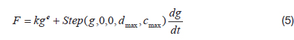
where, g is the penetration of one geometry into another. is the penetration velocity at the contact point. e is a positive real value denoting the force exponent. dmax is a positive real value specifying the boundary penetration, used to apply the maximum damping coefficient cmax.
The selection of parameters, such as time step, contact, penetration, and friction, is explained, as follows.
In simulation problems, it is important to select the proper time step size, in order to produce the correct results. However, for a model with hundreds of bodies all undergoing dynamic contact, we need to balance the convergence efficiency, against the required level of accuracy. The “best” value is determined by the trial and error method. In this work, the range of step size was chosen from 0.0005 to 0.01 second.
The landing of a lunar module can be regarded as a dynamic contact problem between the lunar module and lunar surface. ADAMSTM simulates contacts between two bodies in several ways: solid-to-solid, curve-to-curve, pointto- curve, point-to-plane, curve-to-plane, sphere-to-plane, and sphere-to-sphere. In this study, a solid-to-solid contact was used.
Basically, contact stiffness depends on the shapes and properties of the two contact surfaces [7]. The static contact stiffness K between a rigid sphere and a deformable plate is calculated as [8]:
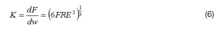
where, F is the impact force acting on the rigid sphere.
This value defines the penetration depth, for the case of full damping. ADAMS/Solver uses a cubic STEP function to increase the damping coefficient from zero, at zero penetration, to the coefficient of full damping, when the penetration reaches the damping penetration.
The exponent of the force deformation is specified by a positive real value. For a stiffening spring characteristic, e > 1.0; for a softening spring characteristic, 0 < e < 1.0. The exponent should normally be set to 1.5 or higher. In this simulation, this variable was assumed to range from 2 to 2.2
In an impact problem, it is necessary to include the friction coefficient between two objects. In this study, this parameter was selected based on the information of the lunar surface. The dynamic and static friction coefficients of the lunar surface are 0.4 and 0.85, in turn [4, 6].
First, we compared the acceleration and velocity results of the body’s center for several simulation cases listed in Table 5, to evaluate what kind of simulation model would be proper for use in a landing simulation, in terms of accuracy and calculation time. Second, 2-2 landing and 1-2-1 landing modes were investigated, for the landing of the lunar module at an inclined attitude on the surface. Third, the tip-over angle was investigated, to evaluate the stability of the 1/6 lunar module.

Simulation case
In this study, a one-sixth size model (42 kg) under the Earth’s gravity was considered to simulate the landing stability of a lunar module (250 kg) on the Moon. The multibody dynamics software, ADAMS, was adopted for the simulation, under the analysis condition listed in Table 3.
4.1 Comparison of analysis cases
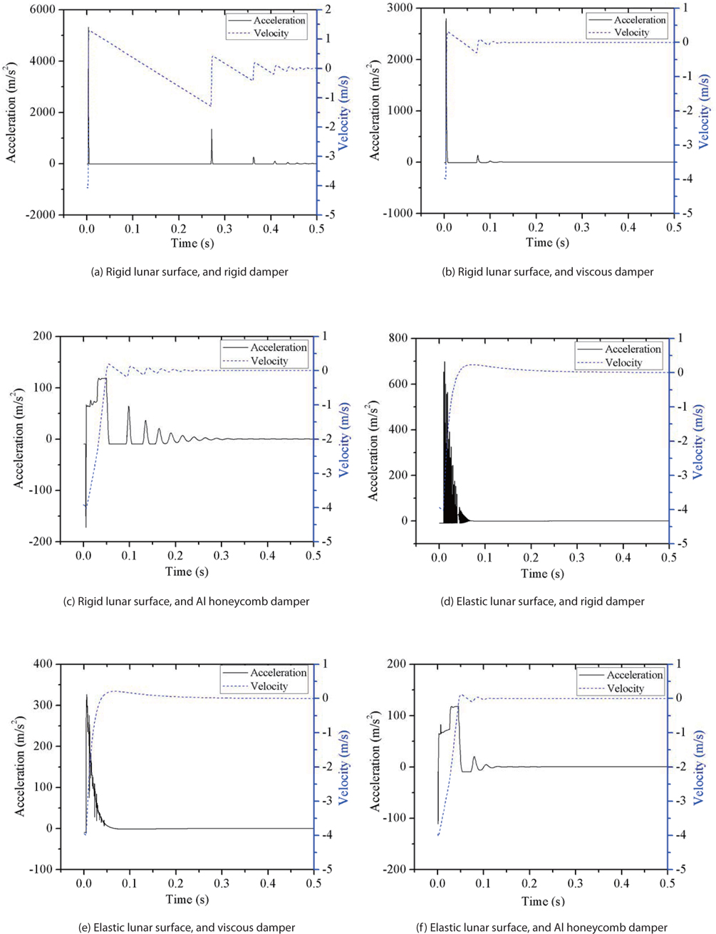
First, we compared the results of the six cases listed in Table 5: two lunar surface models and three damper models were used to find the best analysis model, in terms of accuracy and computation time. The velocity and acceleration of the body’s center were chosen as the parameters for comparison, as shown in Fig. 9. When the lunar surface was assumed to be rigid, and the damper was also rigid, shock energy was not absorbed, as shown in Fig. 9 (a): the velocity changed suddenly, and the acceleration of the body’s center reached its peak of 5,000 m/s2. This means that the rigid surface-rigid damper model is not proper for landing simulations. When a viscous damper was used, the magnitude of acceleration was reduced, but was still large (2,700 m/s2), as shown in Fig. 9 (b). However, when the Al honeycomb damper was used, the acceleration of the body’s center was significantly reduced, to 100 m/s2. This means that the Al honeycomb damper implementation explained in section 3.2 is proper.
When the lunar surface was modeled as an elastic surface, there were a lot of vibrations observed, as in Fig. 9 (d) (rigid damper), and Fig. 9 (e) (viscous damper). This may have resulted because the rigid damper and viscous damper were not able to properly absorb the impact energy. However, when the Al honeycomb damper was used for the same lunar surface condition, the elastic surface produced reasonable analysis results, as in Fig. 9 (f ).
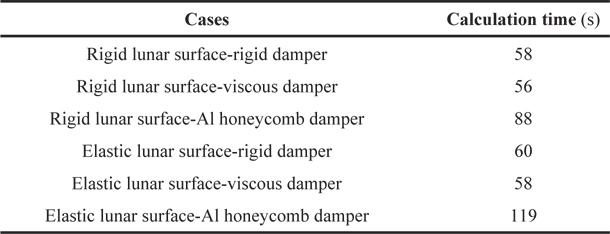
Table 6 shows the computation times of six cases, which were run on a computer (Intel® coreTM i5-2500, 8192MB RAM). As shown, the computation times for the six cases are not very different, meaning there is no merit in using the rigid lunar surface-rigid damper model. So, the elastic surface and Al honeycomb damper model is preferred for the landing stability simulation.
[Table 6.] Comparison of calculation times

Comparison of calculation times
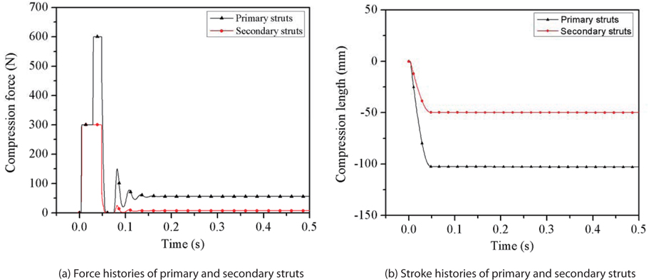
Fig. 10 shows the force and stroke histories of the primary and secondary struts of the one-sixth lunar module, which was modeled with the elastic lunar surface and Al honeycomb damper model. When the lunar module impacted the lunar surface, the aluminum honeycomb shock absorbers of each primary strut started to compress. Due to the simultaneous impact and the symmetry of the model, the compression force and compression length for all the legs were the same. The force acting on the primary strut was so high, that the two stages of the primary struts were crushed. The crushing forces of the first and second stages were 300 N and 600 N, respectively. However, the secondary struts suffered the crush of the first stage: they were subjected to a compression force of 300N and a stroke of nearly 50 mm, because most of the shock energy was absorbed in the primary struts. It can be concluded that most of the energy was absorbed by the aluminum honeycomb shock absorbers attached to the primary struts. Secondary struts were found to play minor roles in energy absorption.
4.2 Landing response of the lunar module at an inclined attitude
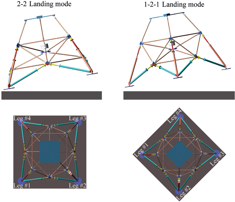
When the lunar module touchdowns on the lunar surface, its attitude is unlikely to be perpendicular to the lunar surface. KARI’s design criterion allows an inclined angle of 10 degrees. We investigated the landing responses of two typical modes: 2-2 landing mode and 1-2-1 landing mode, based on how the footpads make contact with the lunar surface; these are depicted in Fig. 11. In the 2-2 landing mode, two front feet (leg#1 and leg#4) impact simultaneously, and then the two back feet (leg#2 and leg#3) impact simultaneously. In 1-2-1 landing mode, the front foot (leg#1) makes initial contact with the surface, followed by a simultaneous impact of the two center feet (leg#2 and leg#4), and then the impact of the back foot (leg#3).
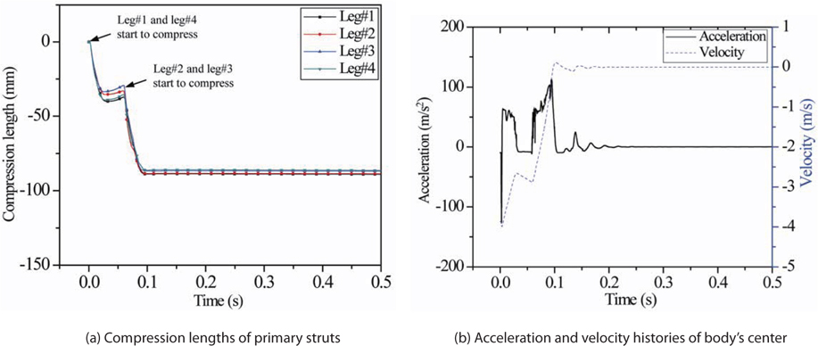
2-2 landing mode at inclined angle of 10 degrees
The responses of the 2-2 landing mode on an elastic surface are investigated in this section. Fig. 12 shows the compression lengths of the primary struts, and the acceleration and velocity of the body’s center. At the time the two front feet impact the surface, the impact energy is mainly absorbed in the primary struts of leg#1 and leg#4. Then, the other legs (leg#2 and leg#3) impact, and they too compress. Interestingly, leg #2 and leg #3 suffer compression between the first two legs’ impact and the second two legs’ impact, because the lunar module is a truss structure, and the force at one leg can be transmitted to the structure. Also, leg#2 and leg#3 suffer from bigger compressive force than the other legs, due to the rotation of the body with respect to the body’s center. Therefore, the front legs have larger compression lengths than the other legs. Since the compression length is around 90 mm, the second stage in the primary strut is compressed, and the crush force is greater than 300 N.
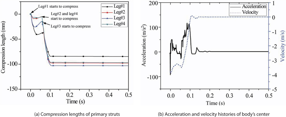
1-2-1 landing mode at inclined attitude of 10 degrees
Fig. 13 shows the compression lengths of the primary struts, and the acceleration and velocity of the body’s center. Leg #1 contacts first, and so the other legs compress, as explained in the 2-2 landing mode case. After leg #1 impacts, leg #2 and leg #4 impact, and then leg #3 impacts. Similar to the 2-2 landing mode, leg #3 has the biggest compression length, which means the force acting on leg #3 is the greatest.
Table 7 shows the compression lengths of the primary struts for level landing, 2-2 landing and 1-2-1 landing modes. The compression lengths for the 2-2 landing mode and the 1-2-1 landing modes are shorter than that for the level landing mode. This may be because the velocity perpendicular to the surface for the 2-2 landing and 1-2-1 landing modes is smaller, than the velocity for the level landing mode. There are extension periods of the honeycomb damper, after the first impact on the lunar surface, as shown in Figs. 12 (a) and 13 (a), although the honeycomb damper is always compressed in the level landing mode, as shown in Fig. 10 (b).
[Table 7.] Comparison of compression length of primary struts
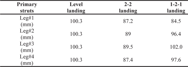
Comparison of compression length of primary struts
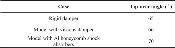
The landing stability on a tilted lunar surface was investigated. To calculate the tip-over angle of the lunar module, simulations were performed for increases of the slope of the lunar surface. The lunar surface was modeled as an elastic surface, and three kinds of damper models were considered: a rigid damper, viscous damper, and aluminum honeycomb damper. Also, two landing modes were compared, to determine which one provided the better landing stability. Tables 8 and 9 show the tip-over angles for the 2-2 landing mode and 1-2-1 landing mode, respectively.
[Table 8.] Tip-over-angle for 2-2 landing mode, with different models of damper
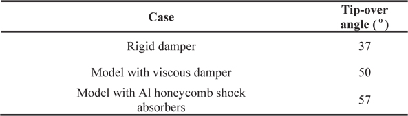
Tip-over-angle for 2-2 landing mode, with different models of damper
[Table 9.] Tip-over angle for 1-2-1 landing mode, with different models of damper

Tip-over angle for 1-2-1 landing mode, with different models of damper
The results show that the 1-2-1 landing mode is more stable than the 2-2 landing mode. The reason is that the moment arm between the body’s center and back foot (leg #3) in the 1-2-1 landing mode is larger, than the moment arm between the body’s center and back foot (leg #2 or leg #3) in the 2-2 landing mode.
The results say that the rigid damper underestimates the tip-over angle, compared with the viscous and aluminum honeycomb dampers. It is concluded that the damping in the lunar module can increase the tip-over angle, since the damper can absorb the impact energy. The theoretical value for the tip-over angle calculated in section 2.2 was 40.30, which is very close to that of the rigid damper case of the 2-2 landing mode (370). This means that the rigid damper is assumed in the theory in section 2.2.
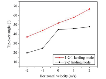
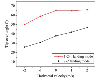
Horizontal velocity can affect the landing stability of the lunar module, as well as the vertical velocity. Since a rigid damper can give a conservative solution, the rigid damper model was preferred. Two lunar surface models were used, namely rigid and elastic surfaces. The positive horizontal velocity of the lunar module means the downward direction of the lunar slope. Figs. 14 and 15 show the tip-over angles of the lunar module for rigid and elastic surfaces, respectively. The tip-over angles for the 1-2-1 landing mode are greater than those of the 2-2 landing mode, which means that the 1-2-1 landing mode is more stable than the 2-2 landing mode.
In this paper, the touchdown dynamic model of a 1/6 lunar module was built in ADAMS, and used in landing simulations, to develop a method for modeling an aluminum honeycomb damper using ADAMS, to compare the stability of the 2-2 landing and 1-2-1 landing modes, and to determine tip-over angles. Simulation results led to the following conclusions: (1) Aluminum honeycomb shock absorbers were modeled successfully in the multi-rigid-body dynamics software ADAMS/View, (2) Two typical landing modes were compared: the 2-2 landing mode and 1-2-1 landing mode. For rigid body impact, the 2-2 landing mode resulted in less stable landing than the 1-2-1 landing mode, (3) The model with the Al honeycomb shock absorbers was more stable than the model with the other dampers (rigid damper, and model with viscous damper).
The current simulation results will be confirmed with future landing tests, and the analysis technique developed in this work can be used for the detailed design of a lunar module structure.


![Properties of lunar surface (Reproduction from [5, 6])](http://oak.go.kr/repository/journal/13489/HGJHC0_2013_v14n4_356_f006.jpg)