Dual phase steels have a microstructure comprising of a polygonal ferrite matrix together with dispersed islands of martensite. There are clear differences between the image quality (IQ) map of the dual phase and the corresponding ferritic/pearlitic structures, both in the as-heat treated and cold rolled conditions. Electron backscatter diffraction (EBSD) techniques were used to study the evolution substructure of steel due to plastic deformation. The martensite-ferrite and ferrite-pearlite interfaces were observed. The interface can be a source of mobile dislocations which the bands seem to originate from the martensite islands. In particular, the use of image quality is highlighted.
Dual-phase steels have gained industrial interest due to their excellent combination of high strength and high formability. Dual-phase steels have a polygonal ferrite matrix together with dispersed islands of high carbon martensite. The microstructures of dual phase steels are mainly composed of equiaxed and elongated ferrite, with martensite volume fractions varying between 20% and 30%. In order to show high fuel efficiency and occupant safety, grain refinement is one of the powerful methods to strengthen dual phase steels without any decrease in ductility [1-6]. Also, a lot of researches goaled to a better understanding of the excellent mechanical properties of dual-phase steels [7-12]. However, there are still some controversies over the mechanisms contributing to the very good mechanical properties of dualphase steels [13-16].
EBSD patterns are able to be used to determine phases, grain boundaries, elastic and plastic strain and the orientation of the crystal lattice with respect to some laboratory reference frame in a material of known crystal structures [17-20]. The orientation can be determined by indexing the pattern. Patterns can be obtained from about 0.2 μm diameter area using a scanning electron microscope with a tungsten filament. The use of EBSD techniques involving a field emission scanning electron microscope (FE-SEM) to investigate the crystal structure is growing in importance for qualitative and quantitative analysis. Particularly in the field of multiphase materials, phases can be identified from significant crystal structure differences by means of EBSD patterns. This method provides the ability to map not only orientation but also the relative quality of the EBSD patterns. In the case of deformed steels, the presence of dislocations causes a local bending and dilation of the crystal lattice planes, which results in electrons being scattered away from the Bragg condition. Hence, the sharpness and contrast of diffraction band edges (i.e. Kikuchi bands) are reduced. This degradation of EBSD sharpness can be utilized to assess the degree of work hardening and plastic deformation [18,21,22].
For multi-phase steels, which contain ferrite, bainite and martensite, it may be possible to differentiate between these structures through good image quality (IQ), even though the crystallographies of these phases are very similar. Each of these phases may have characteristic IQ values, since martensite is heavily dislocated and sheared, bainitic ferrite is less so, and ferrite has the lowest substructure [23]. The IQ is the sum of the detected peaks in the Hough transform, and has some dependence on orientation. It essentially quantifies the ‘sharpness’ of the EBSD patterns. These are affected by lattice distortions, so this can obviously be used to study deformation behaviors.
In this paper, the deformation structure was studied using Electron Backscattered Diffraction (EBSD) techniques. The aim of this study is to explore the possibility of phase identification, and to evaluate the characteristics and extent of plastic deformation, using the IQ parameter.
The steel used in this study was a plain low carbon grade having the following composition: 0.13 wt%C, 0.35 wt%Mn, 0.094 wt%Si, 0.006 wt%P, 0.003 wt%S, 0.033 wt%Cu, 0.068 wt%Ni, 0.030 wt%Cr, 0.012 wt%Mo, 0.008 wt%V and 0.040 wt%Co, supplied by Ivaco, Canada.
The dual-phase structure was generated by annealing at a temperature of 750℃ (i.e. in the two phase austenite plus ferrite region), followed by a water quench, after a hold time of 5 minutes, to transform the austenite to martensite. This structure was compared to the equivalent ferrite/pearlite structure, which was generated by again heat treating at 750℃, but then furnace cooled to room temperature, instead of quenching. After mounting, the specimens were mechanically polished, using in succession SiC, 1 μm diamond paste and 0.05 μm colloidal silica. Specimens were examined by EBSD, in order to determine the polishing time required to minimize the deformation layer due to grinding and polishing. The final polishing time selected was 4 hours, by a vibromet auto polishing device.
To obtain the EBSD data, a Philips XL-30 field emission gunscanning electron microscopy (FE-SEM) with a TSL orientation imaging system was used. The EBSD data were collected and analyzed using the orientation imaging microscopy (OIM) data collection according to known crystallographic data and the TSL software. For SEM analysis an accelerating voltage of 20 kV was used and an automatic scan was done over an arbitrarily selected area, with a range of step sizes. EBSD was carried out on a specimen, which was tilted at 70º.
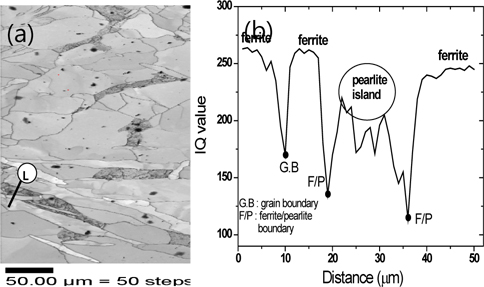
In multiphase steels, phases can be identified through the IQ of the EBSD pattern [18,20]. If the crystal lattice is distorted due to strain, then the corresponding diffraction pattern will be more diffuse, compared to that of an undistorted crystal lattice. Figure 1(a) shows the IQ map of the dual phase steel. Note that the specimens were not etched, and contrast was generated solely from the values of the IQ. In the microstructure, the black regions correspond to the very low quality of the EBSD patterns in those areas. This figure clearly shows the martensite islands in the ferrite matrix as black, signifying the high level of substructure and residual stresses in the martensite. As well, the ferrite also reveals a substructure, as is apparent from the different areas of gray contrast. In dual phase steels, the formation of martensite, in a ferrite matrix causes plastic stresses resulting in these darker regions in the ferrite, through the EBSD IQ map.
Generally, high dislocation density near the martensite is formed due to the transformation shear mechanism, and the volume expansion of 2~3% for the martensitic transformation [24]. More work is required to characterize these features in ferrite. Nevertheless, there seems to be some justification for this hypothesis, by comparing the IQ image of the corresponding ferrite/ pearlite structure (see Fig. 2).
Figure 1(b) is an IQ value profile of the dual phase steel across the martensite islands, and the surrounding ferrite matrix. A plastic shell seems to be formed around the martensite islands, and expanded outwards, as straining proceeds. In this IQ value scan, there appears to be some evidence of a deformed region in the ferrite, at the martensite/ferrite interfaces. It is clear that the martensite islands (in the circled region) can be distinguished from the IQ value, due to the difference of the strain level between the ferrite matrix and martensite islands. Also, the deformed region around the martensite islands can be evaluated, by measuring the IQ profile in Fig. 1(b), between the plastic shell parts.
The IQ map and the IQ value profile of the ferrite/pearlite steel are shown in Fig. 2. The dark gray regions depict pearlite. Also, the light gray and white regions depict ferrite matrix. Mark L indicates the line for line scanning for IQ value line profile. Figure 2(b) shows the IQ value profile of the ferrite/pearlite steel across the pearlite and the surrounding ferrite matrix. The IQ value level of the pearlite is relatively lower than the ferrite matrix. In particular, in the pearlite island, the ferrite represents a lower level than that of the ferrite matrix. This clearly indicates that the ferrite in the pearlite island has suffered plastic deformation, due to the phase transformation.
By comparing the two IQ maps (Figs. 1 and 2), it is apparent that the IQ value profile by EBSD pattern for pearlite is higher than that of martensite. This means that the pearlite phase is not as dark as the martensite due to the amount of distortion at the crystal lattice. Therefore, the IQ value of the martensite is much lower than that of the pearlite. As well, the ferrite has a more uniform gray level, as opposed to the contrast details of the ferrite in the dual phase steel, which may be expected, since pearlite would not be as disruptive to the surrounding ferrite.
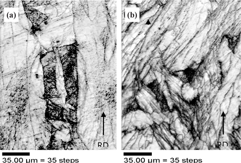
In order to observe the response of these structures to plastic deformation, the samples were cold rolled by a 30% reduction. Figure 3 shows the IQ maps for the ferritic/pearlitic steel, and the dual phase steel sample. In Figure 3(a), even though this microstructure has some slight horizontal scratches on the surface, due to sample preparation, it can be seen that the pearlite islands are elongated along the rolling direction. Also, the interface between the pearlite and ferrite matrix seems relatively clear. On the other hand, there seems to be a lot of distortion around the martensite islands in Figure 3(b), because of the many black lines that are highly concentrated. Although these black lines are arrayed in many orientations, the majority are positioned at an angle of 45º from the rolling direction.
According to previous studies [14,26], the dislocation structure shown in deformed steels had a preferred orientation in the <111> direction, and were identified as screw dislocations. This would seem consistent with the EBSD results, as shown in Fig. 3. Even though the individual dislocations could not be seen through the IQ map, it is clear that the use of EBSD is a relatively easy and powerful tool, when evaluating the substructure of deformed dual phase steels, in comparison to TEM analysis.
Significant dislocation arrays were formed in the ferrite around the martensite islands, as shown in the TEM results from previous researchers [14,25]. In their TEM analyses, they explained that the formation of martensite in a matrix of ferrite causes a high local dislocation density, high residual stresses, and continuous yielding. Of course, it is well known that dislocations can be formed around martensite surrounded by a soft matrix, due to crystal lattice distortion caused by a phase transformation. Since the TEM microstructures were obtained from a very small area, some ambiguity remains concerning the existence of dislocation arrays at the martensite interfaces.
Even though individual dislocations can be sampled easily in TEM, differentiation between martensite and ferrite is not as clear. On the other hand, EBSD can overcome this size problem through its ability to scan relatively large sample areas, and through IQ map evaluation. In order to focus on the area that surrounded the pearlite and martensite islands in these structures, a high magnification and very small step size for kikuchi pattern acquisition were used.
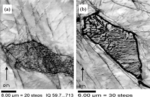
The pearlite and martensite islands in the ferrite matrix are shown in the IQ micrographs in Fig. 4. In the case of Fig. 4(a), the micrograph does not clearly reveal any effect of the applied deformation on the darker regions, in the state of heat-treated condition. On the other hand, dark lines are arrayed in two orientations. These features are likely dislocation-rich walls, or deformation bands. Kumar
Generally, the dislocation cell structure can be produced in ferrite near the martensite, preferentially. Also, the cell size near the martensite is smaller, than that observed in the same ferrite grain away from the martensite [14]. On the basis of the TEM observations, it is believed that the dark lines seen in Figs. 4(a) and 4(b) are deformation bands resulting from the plastic deformation, such as cold rolling. Also, there appear to be some additional smaller lines in the proximity of the martensite/ferrite interface. Sakaki
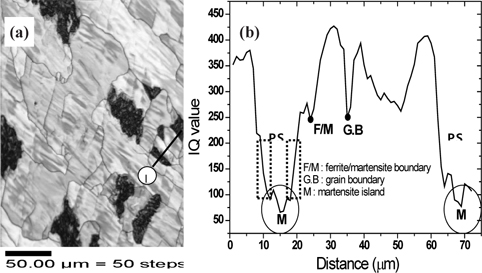
The IQ map and the line profile within the pearlite of the undeformed and deformed ferrite/pearlite sample are shown in Figures 5. In view of the IQ value, the levels of the cementite are very similar, of around 50 IQ value. However, in the case of the ferrite, the IQ values are significantly different, i.e, approximately 440 without deformation, and 150 with deformation. This clearly indicates that the ferrite in the pearlite phase experienced plastic deformation. Wronski et al. [31] also showed well that the analysis of the EBSD data, including the IQ map, measured at different levels of strain in a duplex material demonstrates the two phases behave differently during deformation.
The IQ value can be used to characterize a microstructure of dual phase steel and ferrite/pearlite structure. With calculating the IQ value, a phase differentiation is possible, through the imaging of a substructure due to plastic deformation. In as-heat treated and cold rolled conditions, there are clear differences between the IQ images of dual phase included ferrite/martensite and the corresponding ferritic/pearlitic structures. The IQ map study shows that the ferrite phase in pearlite island has suffered plastic deformation, due to the phase transformation. In the IQ map of deformed dual phase steels, additional shorter lines in the proximity of the martensite and ferrite interface are observed. These indicate that the interface can be a source of mobile dislocations in which the bands seem to originate from the martensite islands.