The implantable antenna provides a better means of communication from the human body to the external environment than an external antenna. An implantable antenna promises improvements in the patient’s care and quality of life. This has resulted in researchers showing keen interest in the study of implantable antennas. Their results have shown innovation in the field of biomedical engineering in glucose monitoring, pacemaker communication, insulin pumps, endoscopy, retinal prosthesis and blood pressure monitoring [1].
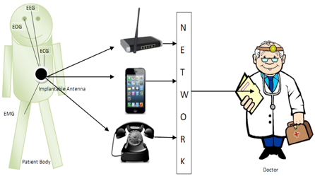
Some patients want a checkup each and every day at a hospital. The proposed system may be a better replacement for this issue. In such a case, a home care unit can be placed in the patient’s house [2]. Via the accessory networking devices, this unit communicates the patient condition regularly to the person concerned at the hospital, as shown in Fig. 1 [1]. Medical implant devices have had to be magnetically coupled to external equipment. This magnetic coupling has required that the device implanted in the patient should be in very close proximity to the external monitoring device, often necessitating body contact for proper operation [3].
In addition, medical implant devices have operated with very slow data rates, due to inductive communication, needing a lot of time for the required data transfer. This has been changed by the establishment of medical implant communication services (MICSs) [4]. Therefore, the MICS overcomes the limitations of medical implant devices. An antenna can be designed in either air, or the dielectric of the body. If the antenna is designed in air, the antenna’s best performance will be achieved when air surrounds the implant. If the implanted antenna is designed in the dielectric of the body, the best performance from the implant will be achieved when the implant is actually inside the body cavity [5].
Therefore, to design an implanted antenna, it is necessary to place the implant within the medium in which it will be expected to operate. In this paper, an implantable antenna is proposed for ISM (Industrial Scientific Medical) applications. The proposed antenna is found to be compact in size, and to have a reasonable return loss of -10 dB, to cover the ISM band. Furthermore, the return loss property of the antenna is insensitive to the variation of the electrical properties of the human body. The MICS frequency band has been chosen to reduce wave attenuation in the complex human environment. As a drawback, the use of the MICS band requires electrically very small antennas [6,7]. Until now, Microstrip (or) PIFA was proposed for implantable devices, which were covered with dielectric materials in the frequency band of 402~405 MHz [8]. Some implanted antennas were analyzed for ISM band applications [9]. We simulate this antenna, which can be effectively be used at the 2.45 GHz Industrial Scientific Medical (ISM) band. The use of larger implantable units restricts the distance of transmission of the signal. This is due to the fact that our body fluids and skin greatly attenuate the signal, and hence it is required to be compact in size, which has an adverse effect on transmission power and coverage. Such problems can be avoided by the usage of repeater units. The radiation characteristics of a tissue implantable antenna mounted over a human body is simulated, using IE3D software.
The organization of this paper is as follows. In Section II, the geometrical details of the proposed antenna are discussed. Section III details the operating principle of the implantable CPW fed antenna. This section also provides proof that the proposed antenna is highly suitable for ISM band medical applications, with its simulation and measured results. This is followed by the conclusion in Section IV.
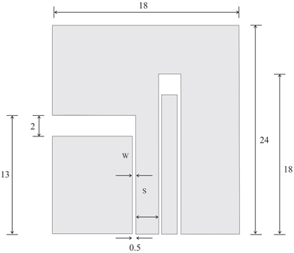
The layouts of the monopole antenna configurations studied in this paper are shown in Fig. 2, as well as their theoretical models. In the theoretical part, the fundamental design equations are derived from the Schwartz-Christo fell transformation in Ref. [10].
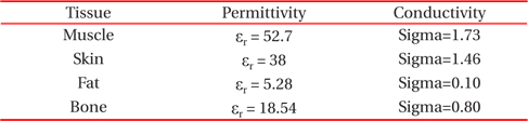
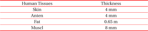
Figure 2 shows the examined geometrical configuration of the implantable CPW fed monopole antenna for ISM band biomedical applications. The antenna was constructed on dielectric ceramic substrate, with thickness of 0.65 mm and dielectric constant εr of 9.8, and implanted into muscle, skin and fat, with permittivity and conductivity as tabulated in Table 1 [12].
[Table 1.] Dielectric properties of human tissues.

Dielectric properties of human tissues.
The basis of the antenna structure is chosen to be a rectangular patch element, with a dimension of 18 × 24 × 0.65 mm3. Two narrow folded slots, including an inverted L- shaped slot and an inverted U- shaped slot, are embedded into the patch. The insertion of the two shaped slots results in the formation of a monopole fed by a CPW feed structure. For the u-shape antenna, a tuning stub is introduced, to enhance the coupling between the slot and the feed line, so as to achieve the ISM band property of the proposed antenna. Thus, the extraction depth and length are the most important parameters that affect the antenna performance, and which need to be studied. Based on the design dimensions shown in Fig. 2, and the prototype, the proposed implantable antenna was designed. The proposed antenna simulation model setup is shown in Fig. 3.
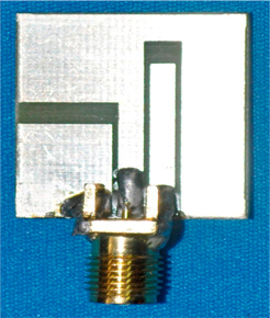
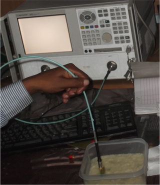
Experimental investigations are needed to validate the simulation results of the implantable CPW fed antenna. Since it is not possible to carry out measurements inside the human body, investigations are performed by measuring laboratory-fabricated prototypes (Fig. 4), inside tissue-equivalent mediums (phantoms). Due to the unavailability of biocompatible materials in some laboratories, we purchased alumina ceramic material from Alibaba Manufacturer, China. The prototype fabrication of the implantable antenna meets all the classical difficulties of miniature antennas. The proposed antenna is fabricated with biocompatible alumina ceramic substrate (εr= 9.8, h= 0.65 mm), as shown in Fig. 4.
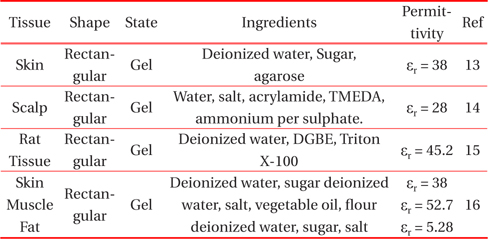
Based on the above, the numerical antenna model must be slightly adjusted, in order to take prototype fabrication considerations into account. Experimental measurements must be carried out with the exact same antenna structure, in order to be able to validate the design. In this case, the main challenge lies in the formulation and characterization of the tissue-emulating materials. The example phantoms and tissue recipes reported in the literature are given in Table 2 [13-16].
[Table 2.] Phantoms used for the testing of implantable antennas.

Phantoms used for the testing of implantable antennas.
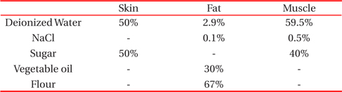
The recipes proposed mainly included ultra pure water, sugar, and salt contents. An increase in sugar content concentration has been found to drastically decrease εr, while slightly increasing σ. An increase in salt content concentration decreases εr, and significantly increases σ, as tabulated in Table 3 [13]. Adding an agarose to solidify the liquids, and form multilayer gel phantoms, was also examined [14].
[Table 3.] Preparation of human body phantom liquids.

Preparation of human body phantom liquids.
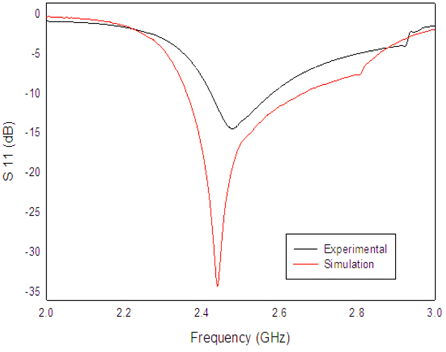
The antenna is connected to a Vector Network Analyzer, as shown in Fig. 5, inside the phantom. S11 measurements are performed when the antenna is in planar state. First, Fig. 6 shows a comparison between the measured and simulated return loss of the antenna in planar state. The simulations are performed using the IE3D simulator Mentor Graphics. Since the IE3D simulator is a 3D simulator, the finite size typically results in a shift of the resonance frequency to lower frequencies, so for the initial design in momentum, to cover the ISM Band, the antenna is designed to resonate at 2.45GHz.
Once fabricated and measured, this design ensures that our antenna will cover the complete requested bandwidth. The required -10 dB impedance bandwidth of the antenna is 320 MHz, in the 2.45 GHz ISM band. The design of implanted low profile antennae, with simplified planar geometrics based on a real human body, is proposed. The radiation performances of the designed low profile antennae are estimated in terms of radiation patterns, radiation efficiency, and specific absorption rate.
The substrate is capable of protecting neighboring tissue phantom surrounding the implanted antenna. The substrate also assists the antenna to be well matched to 50 ohm, through decreasing the effects of highly conductive biological tissues.
The radiation characteristics of the antenna inside the liquid simulating muscle fat skin tissue are determined in terms of radiation patterns and gain. The antenna is directed towards the surface of the gel (muscle, fat and skin), and along the z-direction the distance to the surface of the gel is set to 10mm in the xy-plane, and the antenna is placed in the center of the surface of the human body phantom liquid.
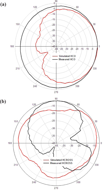
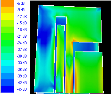
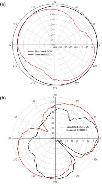
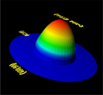
The computed radiation patterns in the E-plane and H-plane are shown in Fig. 7 and Fig. 8, respectively; and the 3D current distribution and 3D geometry of the mapped radiation pattern are shown in Fig. 9 and Fig. 10, respectively. The patterns are computed at 2.45 GHz, at a reference distance of 1 m, using an input power of 1 W.
The maximum gain is equal to -8 dBi for θ= 0 and φ= 0, and the radiation efficiency is 0.23%. These values are comparable to other results in the literature [11]. The radiation efficiency is very low, because the antenna is not in free space, but embedded into human tissue, simulated as a very lossy tissue medium.
The antenna is connected to a Vector Network Analyzer, as shown in Fig. 5, inside the phantom. S11 measurements are performed when the antenna is in planar state. First, Fig. 6 shows a comparison between the measured and simulated return loss of the antenna in planar state. The simulations are performed using the IE3D simulator Mentor Graphics. Since the IE3D simulator is a 3D simulator, the finite size typically results in a shift of the resonance frequency to lower frequencies, so for the initial design in momentum, to cover the ISM Band, the antenna is designed to resonate at 2.45 GHz.
In this paper, an implantable CPW-fed monopole antenna for ISM band biomedical applications is presented, with a compact size of (18 mm × 24 mm × 0.65 mm), and solutions are suggested regarding the design, numerical simulations, and experimental investigations of an implantable CPW-fed monopole antenna for biomedical telemetry. The design of implantable antennas mainly emphasizes miniaturization and biocompatibility. ISM band antennas are being designed for these purposes, which only wake up the implantable medical device when there is a need for information exchange. A homogenous model is adequate for antenna design, but a more sensible model is needed to refine the antenna design, and provide perfect results. Due to the better dielectric constant of alumina ceramic substrates, the implantable antenna exhibits miniaturization, lower return loss, good VSWR, and better impedance matching and high gain, compared to the other implanted antennas. Therefore, the proposed antenna is a suitable candidate for the ISM band frequency of 2.45 GHz, in the field of Biomedical Engineering.

![Hospital applications [1].](http://oak.go.kr/repository/journal/13430/E1TEAO_2014_v15n2_55_f001.jpg)