

Solid state lighting, based on high-brightness Light emitting diodes (LED), has emerged as a new and potentially revolutionary technology that could save up to half of the energy used for lighting applications. Compared with traditional lighting, white LED has the following advantages: small (use of many kinds of associations and flexible array devices), not easily damaged (bear shaking), long lifetime (more than 100,000 hours), low power consumption, and low pollution. Thus, White LED would be the most important light source in the 21st century [1].
White LEDs, based on blue LED chips coated with a yellow emitting phosphor (YAG:Ce), were first reported in 1997 [2]. The blue chip/YAG:Ce system has many advantages. But the lamps fabricated in this manner give a poor colour rendering, because the resulting light is typically deficient in the green and red colours. There are two approaches that are being followed to overcome this problem. In the first approach, white LEDs are made by coating near ultraviolet (n-UV) emitting LED with a mixture of high efficiency red, green and blue emitting phosphors [3], analogous to the fluorescent lamp. This method yields lamps with better colour rendition. Addition of a yellow emitting phosphor further improves the colour rendition index (CRI). Recently, much progress has been made for the emission efficiency of LED chips in the near UV-to-deep blue range [4-7]. However, cost and light output wise, near UV chips are much inferior to blue chips. Thus, the second approach [8], comprised of coating blue excitable, green and red phosphors on blue chip, is, for the time being, considered to be more practicable.
In this paper we describe the effect of change in chip wavelength and particle size, on the characteristics of white LED coated with Y3(Al,Ga)5O12:Ce (green, yellow), and SrS:Eu (red) phosphors.
Y3Al3Ga2O12 and Y3Al4GaO12 activated with Ce (0.7 mol%) phosphors were prepared, by combustion synthesis. Instead of the conventional solution combustion synthesis, we used a modified procedure, which led to the formation of the desired compounds in a single step, as described in our paper [9].
A modified procedure was followed to synthesize SrS:Eu phosphor, also. SrSO4:Eu was first prepared by recrystallization from sulfuric acid (Yamashita's method [10]). SrCO3 was dissolved in hot conc. sulfuric acid. An appropriate quantity of Eu2O3 was then added to this solution. Excess acid was distilled out at 310 °C, in a closed assembly. The SrSO4:Eu thus formed was repeatedly washed with distilled water. This was reduced to SrS:Eu, by the double crucible method [11].
X-ray diffraction patterns were recorded on Philips PANalytical X'pert Pro diffractometer. Photoluminescence (PL) characteristics in the range of 200-700 nm, at room temperature, were studied, using a Hitachi F-4000 spectrofluorimeter, with 1.5 nm spectral slit width.
The phosphor in desired quantity was dispersed in a transparent silicone resin (Wells Electronic Materials Company, 5012-2A and 5012-2B), and the LED was then fabricated by coating the blue LED chip (CREE 458 nm, 300 micron) with the epoxy resin. The electroluminescence (EL) spectra, colour temperature, CIE chromaticity coordinates, CRI, and lumen output at room temperature were measured, using a 300 mm integrating sphere and lumen meter (Hangzhou Zhongwei Photoelectricity Company ZVision ZW 3900). The measurements were carried out at 3.2 V, 20 mA. Particle size characterization was done on an LA-950 Laser Diffraction Particle Size Distribution Analyzer.
The prepared phosphors, Y3(Al,Ga)5O12:Ce (green, yellow) and SrS:Eu (red), were characterized through XRD and PL spectra, and the results are as described in our paper [9]. In our earlier paper, we used diodes of 457 nm, to coat the blend of green and red phosphors. In this paper, we coated the blend of Y3(Al,Ga)5O12:Ce (green, yellow) and SrS:Eu (red) phosphors on the diodes of three different wavelengths, i.e. 438 nm, 457 nm, and 470 nm. All the above wavelength diodes were coated with the same concentration of phosphor blend.
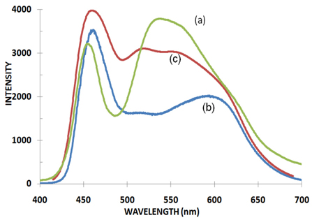
Though Ce3+ emission in these phosphors appears green to the naked eye, it is actually a mixture of green and yellow, owing to the doublet nature of Ce3+ emission. Along with SrS:Eu2+, and blue chip, one gets all 4 (RGYB) colors, which can help in improving the CRI. Fig. 1 shows typical LED spectra, where 6.6 % each of the Y3Al4GaO12:Ce3+ and SrS:Eu2+ phosphors were used.
The intensity scales are chosen, such that the blue emission is at equal heights. The intensities shown in Fig. 1 are not intercomparable. However, in terms of lux, the light outputs are of the same order for the 3 LEDs shown in Fig. 1. Here, the emphasis is on the CRI. All four emissions, viz. blue, green, yellow and red, can be seen, when a mixture of Y3Al4GaO12:Ce3+ and SrS:Eu2+ phosphors was used. The colour can be tuned, by changing the ratio of Y3Al3Ga2O12:Ce3+ /Y3Al4GaO12:Ce3+:SrS:Eu2+, and the phosphor concentration in the epoxy. Colour coordinates of 0.32, 0.34 were typically obtained with CRI 85, when 6 % of Y3Al3Ga2O12:Ce3+ and 3% of SrS:Eu2+ phosphors were used (curve c). The corresponding colour temperature was 6300 K. These results were obtained with a diode wavelength of 457 nm
The unit cell of Y3Al4GaO12:Ce3+ consists of four formula units, with a single type of Y-site. Eight oxygen atoms in a distorted dodecahedron coordinate the Y atom, giving it D2 symmetry. The large Ce3+ ion occupies the 24(c) sites of Y3+ with D2 point group symmetry, and each of the ions is in an almost dodecahedral coordination of eight oxygens, distributed in two groups, depending on their separations. The second coordination shell is made of two Al3+/Ga3+ at about 300 pm, with four quasitetrahedral coordination, four Al3+/Ga3+ at about 335 pm, with six quasioctahedral coordination, and four Y3+ at 367.7 pm, with eight quasidodecahedral coordination, all of them sharing two coordination oxygens with the central Y3+ (or Ce3+). Due to tetragonal symmetry of the dodecahedral yttrium site, the 5d state splits into lower-lying doublet Eg and upper-lying triplet T2g level, which are further split into five levels, due to the given symmetry and spin-orbit interaction. This results in the well-known absorption bands at around 445 and 345 nm, corresponding to transitions to split levels originating from Eg, and 233 nm, related to transitions to levels originated from T2g . The emission is made of seven 5d --> 4f transitions, which overlap to produce a broad band at around 511 nm (Fig. 2).
In order to see the effects of particle size, the phosphors were ground in a ball mill, to reduce the particle size. After ball milling, the particle size of the prepared phosphors was reduced from 100 μm to 0.5-5 μm [12].
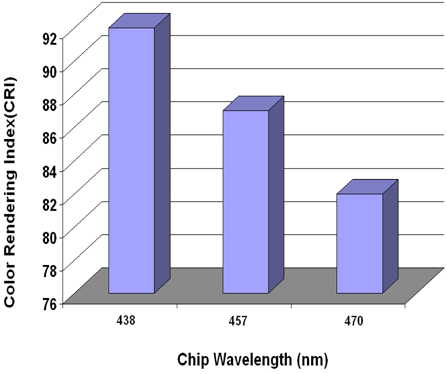
The ball milled phosphors Y3(Al,Ga)5O12:Ce (green, yellow) and SrS:Eu (red), having particle size 0.5-5 μm, were then blended with epoxy resin in appropriate proportion; and coated on the chips of three different wavelengths, i.e. 438 nm, 457 nm and 470 nm blue LEDs. These LEDs were characterized through Lumen Meter, to study the change in the CRI and color coordinates of the white diodes. The resultant CRI obtained with each chip is as shown in the following bar diagram.
Figure 3 shows the dependence of CRI on the chip wavelength selected to coat the blend of phosphors. When the same phosphors were coated on diodes with different wavelengths, the CRI varied accordingly. This is because of the change in excitation band of Y3(Al,Ga)5O12:Ce3+ phosphor, as it matches well with 438 nm LED, and hence gives a better CRI i.e. 92, in comparison with the 457 nm and 470 nm diodes.
Y3(Al,Ga)5O12:Ce3+ and SrS:Eu2+ phosphors could be prepared with simpler methods. One step combustion synthesis using glycine+urea mixed fuels yielded Y3(Al,Ga)5O12:Ce3+ phosphors. LEDs with improved CRI could be fabricated by choosing Y3Al4GaO12:Ce3+ (green and yellow) and SrS:Eu2+ (red) phosphors, along with blue chip (438 nm). The LEDs so fabricated possessed other desirable characteristics, like colour co-ordinates 0.32, 0.33, and colour temperature of 6300 K. Hence, the study shows that more desirable characteristic white LEDs can be fabricated, by selecting the proper chip wavelength. Also, the particle size of coated phosphors can be reduced, to get better w-LEDs, with more light output.

![PL Emission Spectra of Y3Al4GaO12:Ce3+ and SrS:Eu2+ phosphors [9].](http://oak.go.kr/repository/journal/13422/E1TEAO_2014_v15n2_66_f002.jpg)
