The use of photonic approaches to transmit and process microwave signals has been an interesting research area for several decades, due to its advantages of large bandwidth, low loss, and immunity to electromagnetic interference (EMI) [1]. Owing to the more linear conversion of input voltage to optical phase and requiring no bias controller, the LiNbO3 electro-optic phase modulator (PM) attracts a great deal of attention and has a host of applications [2, 3], such as microwave photonic links [4], optoelectronic oscillators [5, 6], optical comb generators, and all-optical microwave filters [7]. The half-wave voltage (Vπ) is one of the most significant parameters to characterize a PM, which is the voltage required to produce π radians optical phase shift and represents the modulation efficiency of the PM. Therefore, the measurement of Vπ is important for PM manufacturers and end users.
Recently, several different methods for measuring the Vπ of a PM in the optical domain using an optical spectrum analyzer (OSA) have been proposed, such as the carrier nulling method [8], sideband nulling method, Carrier/the first sideband (FSB) intensity equalization method and Carrier/FSB intensity ratio method [9]. Nevertheless, most of these methods require high driving power with peak-to-peak voltage significantly higher than Vπ, which may change optoelectronic properties of PM and damage the device under test. And it is inconvenient to fine-tune the RF power manually at each frequency point to meet the critical measurement condition. Moreover, the resolution of commercial OSA is generally larger than 2 GHz, so that it is hard to measure the Vπ of PM in the lower frequency range by using these methods.
The method for measuring Vπ of PM in the electric domain based on the gain of phase-modulated link is also demonstrated [10]. Although this method eliminates the manual adjustment of RF power at each frequency point and does not require high driving power, lots of factors that have to be calibrated beforehand may degrade the measurement accuracy, such as the optical power of laser, optical insertion loss and responsivity of photodiode (PD). Even worse, the responsivity of PD is also frequency-dependent and it is hard to calibrate as well.
In this paper, we propose a method for measuring the Vπ of a PM based on a phase-modulated Mach-Zehnder interferometric demodulation (PM-MZI) photonic link. In the measurement, the Vπ only depends on the RF voltage amplitude input required to achieve 1-dB gain compression of the link (VRF,in,1dB) and the differential delay of Mach-Zehnder interferometer (MZI). And the VRF,in,1dB can be automatically swept using a network analyzer (NA), eliminating the manual adjustment of RF power at every frequency point. The VRF,in,1dB of the link can be reached at low driving power, which ensures the safe operation of the PM under test. Moreover, Vπ can be measured in the low frequency range. Additionally, this method does not depend on the frequency response of the PD.
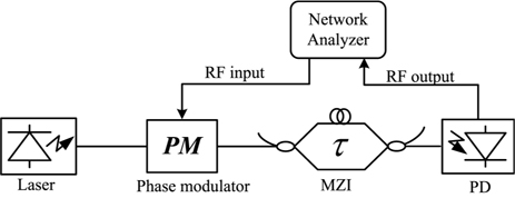
The Fig. 1 shows a PM-MZI link which comprises a laser, an external PM, an asymmetric MZI and a PD. Firstly, the signal is modulated on the phase of optical carrier by the PM. Then, the optical carrier is fed into the MZI which converts phase modulation into intensity modulation. And finally, the RF signal can be directly recovered by a PD. The photocurrent output of the PD is given as follows with the MZI set at quadrature [11]:
where Idc=αP0ℜ/2, α is the total optical insertion loss of the link, P0 is the optical power output of the laser, ℜ is the PD responsivity, τ is the differential delay of the MZI, and φ(t)=πVRFsin(ωt)/Vπ with VRFsin(ωt) as the driving signal.
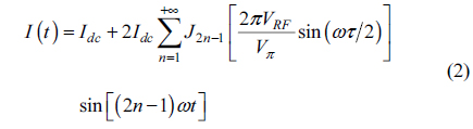
The photocurrent given in the Eq. (1) can be expanded using the Bessel function of the first kind [12] and it is given by
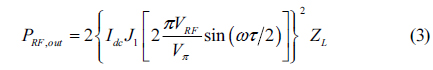
where J2n-1 is the (2n-1)th order Bessel function of the first kind. According to the Eq. (2), the RF power output at the fundamental frequency (PRF,out) of the link can be derived with n=1. And it is given by
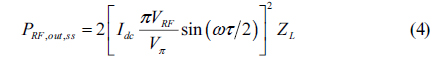
where ZL is the output impedance. Owing to the nonlinearity of the first order Bessel function, the PRF,out will be compressed when the RF power input is large enough. Generally, the small signal approximation of the RF power output at the fundamental frequency (PRF,out,ss) can be obtained using the linear approximation of the 1st order Bessel functions J1(x)=x/2. And it is given as follows:
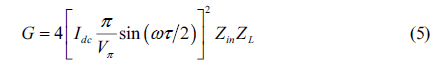
With and Eq. (4), the small-signal RF gain of the PM-MZI link is
As can be seen from Eq. (5), the PM-MZI link exhibits a frequency-dependent gain dictated by the differential delay of MZI. And the free spectral range (FSR) of the gain is equal to the reciprocal of the differential delay of MZI (FSR=1/τ).
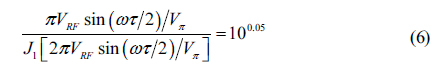
With the quotient (4) over (3) set to 100.1(1 dB), Eq. (6) can be obtained. In this case, the VRF equals the RF voltage amplitude input required to achieve 1-dB gain compression (VRF,in,1dB) of the link.
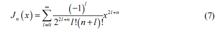
In order to find the relational expression of Vπ, we expand the first order Bessel function of the first kind to the ninth-order polynomial based on the following formula [12]
Consequently, an eighth-degree polynomial equation with the unknown of Vπ is obtained. The relational expression of Vπ can be found by numerically solving this eighth-degree polynomial equation and is given by
As can be seen from Eq. (8), the Vπ of the PM can be calculated directly with the VRF,in,1dB and the differential delay of the MZI. Importantly, the measurement of Vπ is independent of the responsivity of PD, the optical power as well as the optical insertion loss.
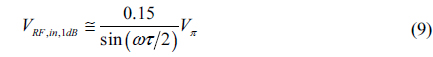
The RF voltage amplitude input required to drive the link into 1-dB compression is related to Vπ by
Obviously, the smallest peak-to-peak voltage swings 30% of Vπ when |sin(ωτ/2)|=1. The required peak-to-peak voltage input based on this method is much smaller than for the previous methods, such as carrier nulling method (VRF,in,pp≅1.53 Vπ) [8], sideband nulling method (VRF,in,pp≅2.439 Vπ), and Carrier/FSB intensity equalization method (VRF,in,pp≅0.914 Vπ) [9]. Therefore, the method presented here with low RF drive voltage ensures the safe operation of the PM.
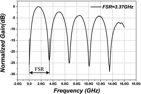
The experimental setup of Vπ measurement is shown in Fig. 1, which is constructed with an Emcore 1772 DFB laser, a Covega LN53 PM, a DSC40S-HLPD PD and an asymmetric MZI. We sweep and normalize the gain of the PM-MZI link by using a network analyzer (Agilent PNA-X N5242A). The FSR of the gain is measured and it is equal to 3.37 GHz, as shown in Fig. 2.
The Eq. (8) shows that the Vπ can be calculated directly from the VRF,in,1dB and the differential delay of MZI. According to FSR=1/τ, the differential delay of MZI can be calculated and it is equal to 297 ps. Therefore, the VRF,in,1dB is required to be measured. The N5242A network analyzer could automatically track the 1-dB gain compression point and the RF power input required to achieve 1-dB gain compression (PRF,in,1dB). With the measured PRF,in,1dB, the VRF,in,1dB can be calculated by using .
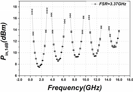
We measure the PRF,in,1dB below 16 GHz with different optical power outputs of laser (P0=60.1 mW, 40.2 mW and 20.8 mW). The error bar chart of PRF,in,1dB is shown in Fig. 3.
As shown in Fig. 3, the PRF,in,1dB of the PM-MZI link is frequency-dependent and does not rely on the optical power output of the laser, which agrees well with Eq. (9). The frequency-dependent PRF,in,1dB is dictated by the differential delay of MZI. Usually, with small MZI differential delay, the PRF,in,1dB varies gently with frequency due to the large FSR. But PRF,in,1dB can not be measured at low frequency because it is so large that it exceeds the maximum output power of the network analyzer. Whereas, with large MZI differential delay, the PRF,in,1dB swings frequently with frequency because of small FSR. And more frequency points meet |sin(ωτ/2)|=1. Therefore, the MZI with large differential delay is recommended for our Vπ measurement method.
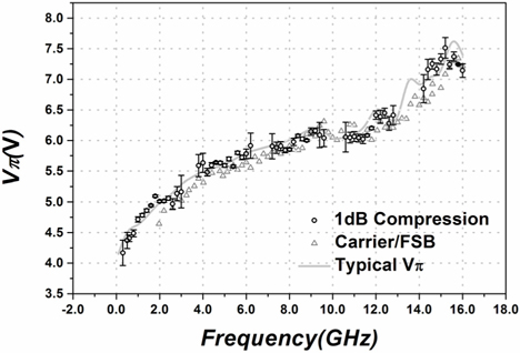
According to the measured PRF,in,1dB in Fig. 3, the VRF,in,1dB can be obtained. Then, the Vπ of PM can be calculated with VRF,in,1dB and the differential delay of MZI τ based on Eq. (8). Furthermore, we also measure the Vπ of the PM using OSA (YOKAGAWA AQ6370) based on the carrier/FSB intensity ratio method [9]. The Vπ measurements based on the novel method (circles) and the carrier/FSB intensity ratio method (triangles) are shown in Fig. 4. As can be seen, the two Vπ measurements and the typical value of Vπ provided by the manufacturer increase with frequency and vary between 4 V and 8 V below 16 GHz. Overall, the two Vπ measurements agree well with the manufacturer’s typical value. The measurement error of carrier/FSB intensity ratio method is less than 0.4 V. However, the measurement error of the proposed method is not more than 0.2 V at the frequency that |sin(ωτ/2)| is close to 1, and less than 0.4 V at the frequency that |sin(ωτ/2)| is away from 1. Therefore, compared with the carrier/FSB intensity ratio method, this method exhibits high accuracy, especially when the measurement is implemented with a large MZI differential delay because more frequency points meet |sin(ωτ/2)|=1.
In this paper, we report a novel and simple method for measuring the Vπ of a PM based on PM-MZI photonic link. The theory shows that the Vπ of a PM can be calculated directly with VRF,in,1dB and the differential delay of MZI. In the experiment, we measure the Vπ of a PM using the proposed method and the carrier/FSB intensity ratio method, respectively. And the two Vπ measurements agree well with the typical value provided by the manufacturer.
Compared with the previously reported methods, this novel method avoids the process of manual adjustment of RF power and eliminates the dependence on responsivity of PD, optical power and optical insertion loss. Moreover, Based on this method, the Vπ of a PM can be measured in the low frequency range and with low lever RF driving amplitude, smaller than 0.5 Vπ, which ensures the safe operation of the device under test. Therefore, it is an attractively alternative method to measure the Vπ of PM.