The use of analog optical links to transmit or distribute the radio frequency (RF) has attracted a great deal of attention over the past decades, due to its advantages of large bandwidth, low loss, and immunity to electromagnetic interference. Analog optical links have a host of commercial and military applications, such as cable television, radio over fiber, remote antenna, satellite communications and phase-array radars [1]. The most common scheme of analog optical links is intensity modulation and direct detection (IMDD) employing an external Mach-Zehnder modulator (MZM), which is free of the resonance distortion and provides a larger bandwidth than the direct modulation of a laser.
A key characteristic of the analog optical links is the spurious-free dynamic range (SFDR) that is defined as the range of input powers in which the signal is above the noise floor and intermodulation distortion is below the noise floor [1]. Generally, the third-order intermodulation distortion (IMD3) is the main restricting factor of the SFDR, which is inherently introduced by the nonlinear transfer function of an MZM. Therefore, numerous methods have been proposed to suppress the IMD3 of the IMDD links, including predistortion linearization [2-5], polarization mixing [6-7], dual-wavelength input [8-9], dual-serial modulation [10-11] and dual-parallel modulation (DPM) [12-14]. The predistortion linearization reduces the distortion in the electronic domain, and its electric circuit is usually complicated. The polarization mixing and the dual-wavelength input lack flexibility in attaining the optimum performance, as is attributed to the use of a single MZM. The dual-serial modulation suffers the even order distortion and is limited to sub-octave applications. However, the DPM offers greater flexibility in attaining the optimum performance by using two spatially distinct modulators and can be used in multi-octave applications when the two MZMs operate at the quadrature point. The DPM has been implemented using the coherent approach [12] and in the incoherent way with a single optical source [14]. In the coherent DPM, the optical power is asymmetrically divided by a polarization-maintaining optical coupler, then fed into two MZMs respectively, and finally recombined by an optical coupler. An optical phase shifter is required to maintain the quadrature between the outputs of the two MZMs in order to prevent the recreation of distortion products [13]. Considering the high sensitivity of the optical phase on the disturbance of the environment, a feedback loop controller is needed to actively adjust the phase shifter. The incoherent DPM with a single optical source employs a polarization beam combiner to recombine the outputs of the two MZMs, which prevents the use of the additional phase shifter and the loop controller.
In this study, we present an incoherent DPM linearization method employing dual wavelengths. By the use of two optical sources operating at the two different wavelengths, the linearization method presented here does not require an additional optical phase shifter to maintain the quadrature between the outputs of the two MZMs [12] and avoids the recreation of intermodulation distortions due to the polarization coupling in the long-haul single mode fiber (SMF) [14]. Therefore, the dual-wavelength DPM (DWDPM) is a good alternative for the high-linearity optical links. However, this DWDPM requires the two optical sources to maintain at a constant power ratio. So the SFDR impairment caused by the optical power drifting is numerically simulated.
The rest of this paper is organized as follows: In Section 2, the intermodulation distortions and the gain compression of a single MZM link are analyzed using Taylor’s series. The operating theory of the DWDPM is also presented. In Section 3, the DWDPM is experimentally demonstrated with the commercially available components. The SFDR and the compression dynamic range (CDR) of the DWDPM linearized link and the single MZM link are measured, respectively. The conclusion is drawn in Section 4.
2.1. The Distortions of a Single MZM Link
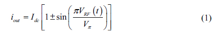
Usually, a conventional single MZM link is composed of a laser, an MZM, a PD and an optical fiber. A continuous-wave laser beam is first modulated by an RF signal in the MZM. After transmitting through a length of optical fiber, the laser beam is fed into the PD that recovers the RF signal from the optical carrier. Generally, the MZM is biased at the positive quadrature (+QUAD) or the negative quadrature (− QUAD) to maximize the gain of the optical link and avoid the even-order distortions. In these cases, the output photocurrent of the single MZM link can be given as below:

where

where
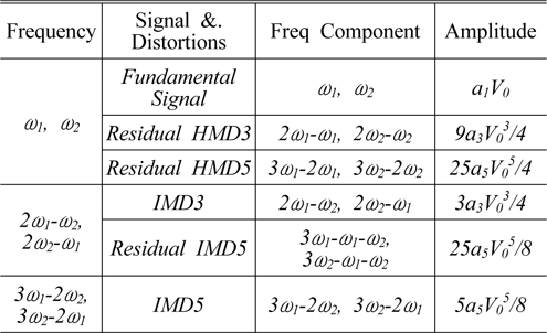
[TABLE 1.] The amplitudes of the signal and the distortions output from a single MZM link

The amplitudes of the signal and the distortions output from a single MZM link
where
2.2. The Dual-wavelength Dual-parallel Modulation
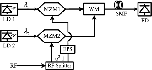
The schematic diagram of the DWDPM linearized link is shown in Fig. 1. The two continuous-wave laser beams are fed into the two MZMs, and modulated by the RF signals, respectively. Then, the two modulated laser beams are combined using a wavelength multiplexer (WM), and finally injected into a PD. The primary path with a large optical power is modulated by a small RF signal, while the secondary path with a small optical power is modulated by a large RF power and 180° out of the phase relative to the primary path. Therefore, when a two-tone RF signal is input in the DWDPM link, the carrier-to-intermodulation ratio (CIR) of the primary path is larger than that of the secondary. With the proper control of the input optical power of the second path, the IMD3 produced in the secondary path can be equal in magnitude to that produced in the primary path, while the fundamental signal of primary path is larger than that of the secondary path. Moreover, the IMD3s of both paths are opposite in phase as well as the fundamental signals of both paths. So the IMD3 of the link can be cancelled with a penalty of a little reduction of the fundamental signal. In this case, the residual IMD5 becomes the dominating intermodulation distortion and limits the SFDR of the optical link. Particularly, the two lasers operate at two different wavelengths to prevent the beatings of two MZM’s outputs lying in the bandwidth of the modulated signal.
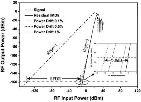
The major concern of the DWDPM linearized link is the SFDR impairment caused by the optical power fluctuation of the two lasers. In order to analyze this impairment, we numerically simulate the SFDR of the DWDPM linearized link under the shot noise limitation with the optical power of the secondary laser drifting and that of the primary laser held constant, as shown in Fig. 2. It is indicated that the SFDR is exacerbated by 1.2dB, 4dB and 5.8dB respectively, when the optical power of the secondary laser drifts by 0.1%, 0.5% and 1%. The output-power stability of the commercial laser diode controller working in the constant power mode can attain 0.02%, so a high SFDR can be obtained using the DWDPM method.
III. EXPERIMENTAL SETUP AND RESULTS
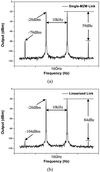
We experimentally compare a DWDPM linearized link with an unlinearized single MZM link. The single MZM link is constructed with an EM4 DFB laser, a Discovery DSC40S PD and a Covega MZM biased at +QUAD. The intermodulation (
The DWDPM linearized link is also constructed with the commercial components. The primary path is made up of an EM4 DFB laser operating at 1552.52 nm and a Covega MZM biased at +QUAD, while the secondary path comprises an Ortel DFB laser operating at 1535.82 nm and an MZM biased at +QUAD. The RF input signal is divided by a 6 dB RF power splitter and modulated on the two paths. An electric phase shifter is used to maintain opposite in phase between the inputs of the two MZMs. The optical signal outputs of the two paths are combined using a WM and injected into a DSC40S PD. With the proper adjustment of the input optical power of the secondary path, the IMD3 produced in this path can be equal in magnitude to those produced in the primary path. The IMD3 produced in the two paths are opposite in phase. Hence, the IMD3 of the linearized link can be suppressed with a penalty of a little reduction of the fundamental signal. The intermodulation (
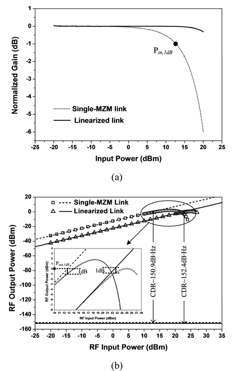
The gain of the linearized link is −22.4 dB and it is smaller by 9.8 dB than that of the single MZM link. This is attributed to the following reasons: (1) the RF power input of the linearized link is attenuated by 6 dB before inputting into the primary path because of using a 6 dB RF splitter; (2) the fundamental signal of the primary path subtracts that of the secondary path when suppressing the IMD3; (3) the RF gain of an optical link is proportional to the square of the output DC photocurrent, but due to the use of a wavelength multiplexer, the output DC photocurrent of the primary path in the linearized link is smaller than that for the single MZM link. The output DC photocurrent of the linearized link is 5.8 mA and that of the single MZM link equals 6.7 mA. Furthermore, we measure the noise floors of both links with Agilent spectrum analyzer E4440A. The noise floor of the linearized link is equal to −152.1 dBm/Hz and smaller than that of the single MZM link (−150.8 dBm/Hz), because the dominated noises of both links are proportional to the output DC photocurrent.
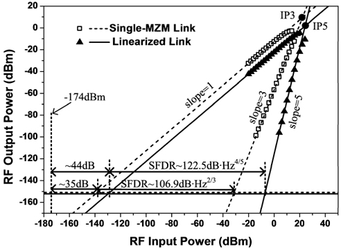
The SFDRs of both optical links are also measured. The measured data of both links are linearly fitted and the fitted lines are extrapolated, as shown in Fig. 4. As can be seen, the output fundamental signals of both links increase with the RF power input and their slopes are equal to 1. Moreover, the intermodulation (

According to the theory of Section 2, both the IMD3 and the residual HMD3 are proportional to
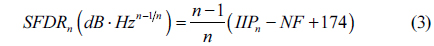
The CDR is also an important performance metric of the optical links. It is the range of the input powers over which the signal is above the noise, and the gain is compressed by 1 dB. The mathematical expression of the CDR is shown as below.

According to the Eq.4, the CDRs of both links are measured, and equal 150.9 dB·Hz and 152.4 dB·Hz, as shown in Fig. 5(b). Comparing with the
In this paper, we present and experimentally demonstrate the DWDPM linearization method. This DPM employing dual wavelengths prevents the use of an additional phase shifter and avoids the recreation of the intermodulation distortions due to the polarization coupling in the long-haul SMF. Moreover, the simulation results show that a high SFDR can be obtained readily by using this linearization method. We construct the DWDPM linearized link and the unlinearized single MZM link with the commercially available devices and compare the performance of both links. The experimental results show that the IMD3 of the linearized link is suppressed and the residual IMD5 becomes the dominating distortion. The intermodulation distortion of the linearized link is suppressed by 25 dB compared with that of the unlinearized single MZM link,. And the SFDR of the linearized link is now 122.5 dB ・Hz4/5, which is improved by 15.6 dB after linearization. Furthermore, the RF power input required to achieve 1−dB gain compression and the CDR of the linearized link are also improved by 10 dB and 1.5 dB, respectively.