검색 전체 메뉴
PDF
맨 위로
OA 학술지
3D Image Correlator using Computational Integral Imaging Reconstruction Based on Modified Convolution Property of Periodic Functions
  • 비영리 CC BY-NC
  • 비영리 CC BY-NC
ABSTRACT
3D Image Correlator using Computational Integral Imaging Reconstruction Based on Modified Convolution Property of Periodic Functions
KEYWORD
Integral imaging , 3D correlation , Elemental images , Lenslet array
  • I. INTRODUCTION

    Occluded objects have been an interesting research area for the field of three-dimensional (3D) object visualization and recognition. Recently, several approaches employed a 3D imaging technique to solve the occlusion problem [1-9]. Among them, integral imaging can be considered as one of the promising solutions, and thus some techniquesbased on integral imaging have been proposed for 3D recognition of partially occluded objects. Integral imaging is a method of recording and displaying techniques for 3D scenes with the lenslet array. The recorded elemental images consist of several two-dimensional (2D) images with different perspectives [10-17]. In 2007, a 3D image correlator using the computational integral imaging reconstruction (CIIR) method was proposed [6]. In CIIR, the plane images were generated by the magnification and superimposition process of elemental images. Each plane image contains both focused and defocused images for occlusion and target objects. This enables us to recognize target objects with occlusion. However, the CIIR process may produce the addition of blur noises in plane images due to the interpolated images and high computation loads. To overcome this problem, the modified CIIR-based 3D correlator using smart pixel mapping, which can reduce the magnification factor and thus improve the correlation performance, was proposed in 2008 [7]. However, this method also utilized the magnification process to generate the depth-converted plane images.

    Recently, a depth slicing method using a convolution property between periodic functions (CPPF) has been proposed to produce the plane image array, which is similar to plane images from the previous CIIR method [18, 19]. In integral imaging with the lenslet array, an elemental image has periodic property depending on object depth. This method takes advantage of the periodic property of spatial frequency of an elemental image. The CPPF is performed by convolution between the elemental image and the 2D δ-function array whose spatial period corresponds with target depth. As a result, the targeting depth image can be reconstructed as the structure of the plane image arrays with fast calculation time compared with the previous CIIR method. In addition, CPPF technique can be applied to optical 3D refocusing display with the lenslet array [20]. Here, 3D objects with their own perspectives can be reconstructed to be refocused on their depth in the space for viewers.

    In this paper, we propose a 3D image correlator using the computational reconstruction based on the modified CPPF for partially occluded object recognition. We introduce a modified CPPF (MCPPF) method for sub-images to produce the plane sub-image arrays (PSAs) without magnification and superimposition processes used in the conventional methods. In the proposed correlator, elemental images of the reference and target objects are captured by the image sensor through the lenslet array. And, the recorded elemental images are transformed to the sub-images, which contain different perspectives according to the viewing direction. The proposed MCPPF method can be applied to these sub-image arrays for reconstruction of the 3DPSAs. Only the target PSA is reconstructed on the right plane where the target object was originally located and contains clearly focused perspectives. On the other hand, other target PSAs are reconstructed on the various reconstruction planes where the focused and blurred images are mixed. 3D object recognition is performed through cross-correlations between the reference and the target PSAs. To show the feasibility of the proposed method, some preliminary experiments on the target objects are carried out and the results are presented.

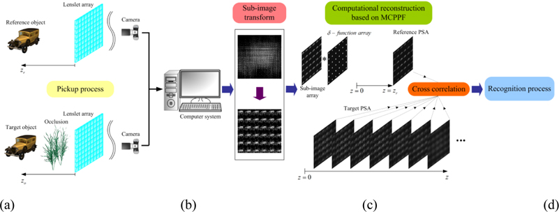
    II. PROPOSED MCPPF-BASED 3D IMAGE CORRELATOR

    Figure 1 shows the schematic diagram of the proposed method. The proposed method is divided into four processes; (1) pickup, (2) sub-image transform, (3) computational reconstruction using MCPPF and (4) recognition processes.

       2.1. Pickup Process

    The first process of the proposed method is pickup of 3D objects. This is the same as the conventional pickup process in integral imaging. The lenslet array is used to capture 3D objects. We assume that a reference object R(xr, yr, zr) is located at the known distance of zr in front of a lenslet array in the pickup system as shown in Fig. 1(a). And a target object O(xo, yo, zo), to be recognized is partially occluded by the occlusion object and located at an arbitrary distance of zo in front of the lenslet array. Then elemental images of the reference and target objects are recorded by the lenslet array and the 2D image sensor. The recorded elemental images of the reference and target objects are stored for the use of the next process.

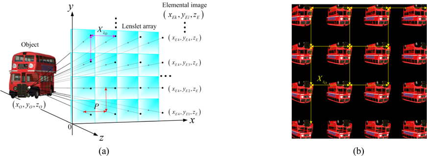
    The conventional pickup process of an integral imaging system by using the direct pickup method is based on ray optics. The geometrical relationship between a point object and its corresponding point images on the elemental image plane is shown in Fig. 2(a). In the conventional integral imaging system with planar lenslet array, the geometrical relation of 2D form is given by

    In the Fig. 2(a) and Eq. (1), the origin of the coordinates is the edge of the elemental lens located at the bottom of the lenslet array. The object point (xo, yo, zo) is the position along the x, y, and z axes, respectively. P represents the distance between the optical centers of the neighboring elemental lenses and is assumed to be the same as the lateral length of an elemental image. f is the focal length of an elemental lens in a planar lenslet array. xEk and yEl are the image point by the kth and lth elemental lenses, respectively. The imaging distance of a point object measured from lenslet array is zE= zO f / (zO + f ). XZo is depth-dependent spatial period. However, due to the limit of resolution of a pickup device, Eq. (1) should be converted into pixel units. Thus the pixelated version of Eq. (1) is denoted by

    where N, P, and kmax are lateral resolution of the elemental image array in one-dimensional (1D) condition, the diameter of an elemental image and the lateral number of elemental lenses, respectively.

    From the geometrical relationship, the 1D form of spatial period depending on object depth is given by |xEixE(i-1)|, 2 ≤ i≤ kmax. Then the depth dependent spatial period is to be |xEixE(i-1)|= |zOP / (zO + f )|. Hence, the pixelated version is denoted by

    Equation (3) implies that the intensity of the elemental image corresponding with an object locating specific depth is imaged with the same interval on the imaging plane as described in Fig. 2(b). Thus, a lenslet array in an integral imaging system may be regarded as the convertor which converts depth information of 3D space changes into 2D periodic information and vice versa.

       2.2. Sub-image Transform

    The recorded elemental images do not have the characteristic of the shift invariance. That is, the projected small images in elemental images are scale-changed if the 3D object is located at different locations. For this reason, we apply the sub-image transform to the recorded elemental images. The sub-image array can provide both shift invariance and the whole projected image in elemental images [5]. The subimage transform can be performed based on either single pixel extraction or multiple-pixel extraction. In this paper, our intention is to apply the concept of conventional CPPF to sub-images for the proposed 3D image correlator. Therefore, the conventional CPPF technique can be modified for subimages.

    We explain the principle of the proposed MCPPF method for sub-image array. The lateral resolution of the elemental image array N is given by N= n× kmax when an elemental image is composed of n pixels. The xCEk may be represented as ordered pair (k , m), where k is index of an elemental image and m is given by m= xCEk – (k – 1)n. m is order of pixel in kth elemental image and 1≤ mn. The lateral resolution of sub-image array is the same as that of the elemental image array, N. If the number of sub-image array is jmax and each sub-image is composed of ξ pixels, then the N can be described by N=ξ× jmax. A pixel in the sub-image array may be also represented as ordered pair ( j, η), where j is a sub-image number and η is order of the pixel in j th sub-image and 1≤ηξ. In this variable correspondence, we can find the relationship as follows

    where c is the number of pixels to be extracted for sub-image transform.

    To show the periodic property of sub-image array adequately, let us consider the condition c=1 as shown in Fig. 3. The pixel correspondence between elemental image array and sub-image array may be represented as follows

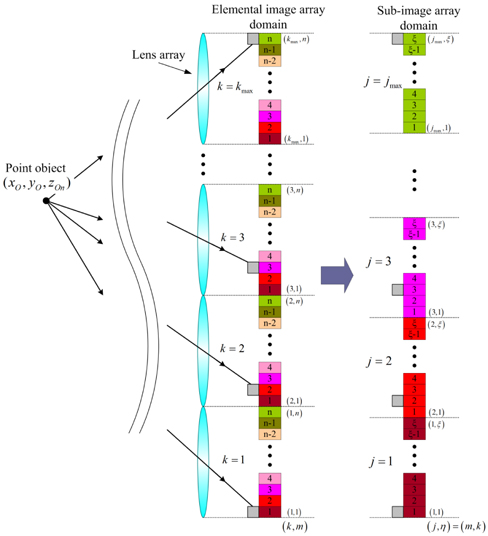
    A pixel position on the sub-image array can be represented as the ordered pair ( j, η) by

    Hence, the 1D form of spatial period in sub-image domain is given by |sis(i-1)|, 2 ≤ i≤ jmax. The detailed version of spatial period is given by

    For example, in Fig. 3, suppose n and kmax are 10 pixels and 9, respectively. Then, ξ and jmax are 9 pixels and 10, respectively. In this condition, if the depth dependent spatial period of the elemental image, XZo, is 11 pixels, then that of the sub-image array, Xsub, is 10 pixels.

    In this paper, the multiple-pixel extraction method is used to increase the resolution of sub-images [4]. Since the multiple-pixel extraction is based on the block combination from each elemental image, the spatial period of each pixel within the block is the same with that of the single pixel extraction method. Therefore, we can apply Eq. (7) to sub-images generated by multiple-pixel extraction.

       2.3. Computational Reconstruction using MCPPF

    In the third process of the proposed method, we apply the MCPPF technique to the recorded sub-images in order to generate 3D PSAs for object recognition. In the transformed sub-image array, the sub-image has a spatially periodic property, and the spatial period is dependent on the depth of an object.

    Mostly, depth extraction or recognition process in various methods is followed in the reverse process of obtaining multiple 2D images from 3D scenes. On the other hand, the MCPPF is to use the superimposing property of convolution between a set of periodic functions and periodic δ-function array to discriminate target periodic spatial information from the input function. The 3D image reconstruction method using MCPPF is as follows.

    The intensity of 2D image may be written as g(xE) = f(xE) ⊕ h(xE), where ⊕ denotes the convolution, xE represents the x coordinate on the imaging plane, f(xE) represents the scaled object intensity, and h(xE) represents the intensity impulse response, respectively. Moreover, depth-dependent image intensity of a 3D object can be represented as g(xE)|Zo = f(xE)|Zoh(xE)|Zo. Assuming the geometrical optics condition (λ→0), the intensity impulse response h(xE)|Zo can be represented by the δ-function. Thus, the intensity of the sub-image array at the corresponding object depth zO may be written as

    Although the object intensity is continuously distributed along the z-axis, the intensity impulse response of the sub-image array is represented as a discrete spatial period because of the limited resolution of a pick-up device sensor. Hence, the sub-image image array may be represented as G(xE)=Σg(xE)|Zo. To discriminate the depth information in a sub-image image array, the MCPPF method can perform, G(xE) ⊕ h(xE)|Zo, more specifically the convolution property between periodic δ-function arrays.

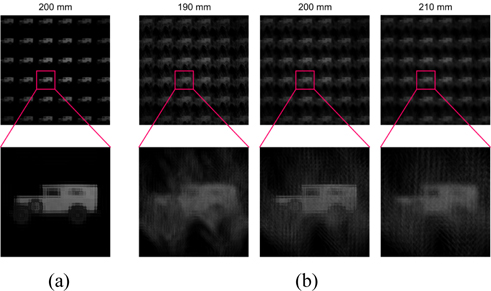
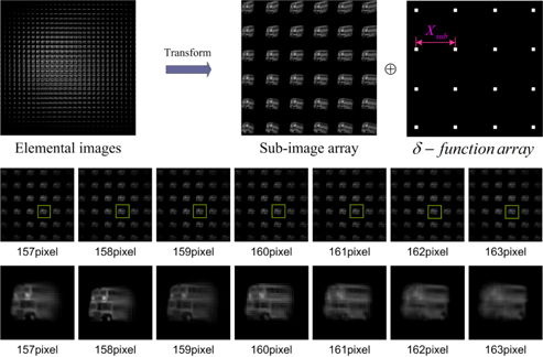
    The 3D image reconstruction process using MCPPF is illustrated in Fig. 4. The pickup condition of the elemental image is as follows. The focal length and the diameter of an elemental lens are 15 mm and 5 mm, respectively. The size of the lenslet array is 30×30. The resolution of the elemental image is 900×900 pixels. The 3D object is located along the z-axes. The right side of the arrow mark in Fig. 4 represents the convolution process between the sub-image array and a δ-function array. The pixel extraction factor in Eq. (4) is applied by c=5. The resolution of a sub-image is 150×150 pixels. The Xsub is spatial period of δ-function array, and the spatial period varies depending on target depth. The images arranged in the middle of Fig. 4 are output results of the MCPPF according to spatial period with 1 pixel interval. To observe the results clearly, the enlarged images are prepared at the bottom of Fig. 4.

       2.4. Recognition Process

    From the process of computational reconstruction based on MCPPF, we can reconstruct the reference and target PSAs. First, the reference PSA is reconstructed on the known zr-plane for the reference object. This is called the reference template. Next, for the partially occluded target object, a set of target PSAs are reconstructed on each reconstruction plane by changing the distance z from the lenslet array as shown in Fig. 1(c). Among them, the target PSA reconstructed at the zo-plane of the original position of the target object during the pickup process has highly focused images of the target object. On the other hand, the other target PSAs reconstructed on the z-planes far away from the zo-plane become out of focus.

    Once a target PSA PO(x, y, z) of the target object reconstructed at the arbitrary distance of z using the MCPPF technique is generated, the correlation process can be performed between the target PSA of PO(x, y, z) and the reference template of PR(x, y, zr). Accordingly, we calculate the correlation result using the following correlation operation as given by

    where * denotes the complex conjugate. It is seen that the correlation peak C(z) is a function of distance z and the behavior of C(z) such as sharpness can be a performance measure for 3D object recognition. This correlation process is repeated for all target PSAs reconstructed on z-planes by varying the distance z within the desired depth range. In fact, since the target PSA with the most highly focused target image is reconstructed at the zo-plane, a sharp correlation peak may be expected to be occurred on the zo-plane through the correlations between the known reference template and target PSAs of the target object.

    III. EXPERIMENTAL RESULTS AND DISCUSSIONS

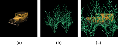
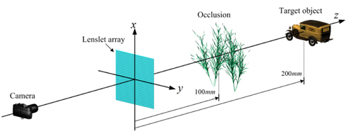
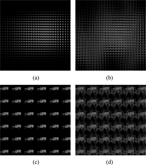
    To demonstrate the feasibility of our proposed 3D image correlator, the preliminary experiment on the 3D objects in space was performed. In the experiment, a 3D object (car) is employed as reference test object as illustrated in Fig. 5(a). And, the occlusion (a bundle of plants) is shown in Fig. 5(b). Figure 5(c) shows the camera view image as the object and the occlusion are arranged inthe object field.

    The experimental structure is shown in Fig. 6. The 3D object and occlusion are located at 200 mm and 100 mm from the lenslet array, respectively. Here the lenslet array is composed of 30×30 lenslets, and the lenslet diameter and the focal length are 5 mm and 15 mm, respectively.

    Using the experimental setup of Fig. 6, we first recorded the elemental images of reference objects which were located at a known position z=200 mm in front of a lenslet array. And, we captured the elemental image array of the unknown target object, which was located at an arbitrary position behind occlusion. Figure 7(a) and (b) show the captured elemental images for reference object and partially occluded object, respectively. And the corresponding subimages are shown in Fig. 7(c) and (d) after sub-image transform. The resolutions of the elemental images and sub-images are 900×900 pixels.

    Figure 8(a) shows the reconstructed PSA of reference object using the computational reconstruction based on MCPPF for sub-images of Fig. 7(c), which the reconstruction depth was 200 mm. Using the sub-images of the partially occluded object shown in Fig. 7(d), we generated their target PSAs according to the distances from 170 mm to 230 mm with the step of 5 mm. Some examples are shown in Fig. 8(b).

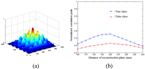
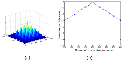
    With the reference PSA and target PSAs, the correlation performances of the proposed method were measured using the correlation operation of Eq. (9). Correlation results were calculated by conducting the correlation between the reference PSA and a series of the target PSAs. The correlation results are shown in Figs. 9 and 10. Figure 9 shows the auto-correlation results of the reference object shown in Fig. 5(a). The correlation array was obtained due to the image array structure of PSAs. Among them, the maximum correlation peak was measured for object recognition. The curve of correlation peaks from the proposed method along the distance z was shown in Fig. 9(b). This result indicates that the ‘car’ object is located at z=200 mm because the maximum of correlation peaks is obtained at this distance.

    And the correlation result for the partially occluded objects as shown in Fig. 5(c) was shown in Fig. 10(a). The curve of maximum correlation peaks for two different cars (True car and False car) were calculated and presented in Fig. 10(b).

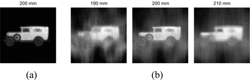
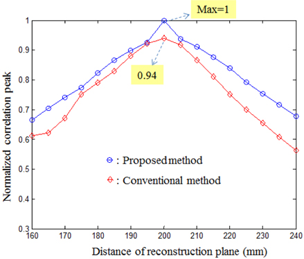
    In addition, we compared the proposed method with the conventional method based on CIIR [7]. The comparison experiments were performed under the same condition. The recorded elemental images were used to generate the CIIR images. The CIIR images for the reference object and the unknown target object were shown in Fig. 11. We compared correlation peaks of partially occluded object between proposed and conventional methods as shown in Fig. 12. Each correlation peak was normalized using the value of the maximum correlation peak obtained in the proposed method. For the conventional method, the maximum value of correlation peak was approximately 0.94. It is seen that the proposed method provides not only higher correlation peak but also sharper characteristic of correlation peaks than the conventional method. This is because our method can remove the blurring effect due to the magnification and superimposing processes of the CIIR process.

    IV. CONCLUSIONS

    In conclusion, we proposed a new 3D image correlator using the computational reconstruction based on MCPPF for partially occluded object recognition. In the proposed correlator, PSAs generated from MCPPF were used for 3D object recognition and thus we can recognize the partially occluded 3D object using the maximum peaks correlated with the reference object. Some preliminary experiments show the usefulness of the proposed method by comparison with the conventional method using CIIR.

참고문헌
  • 1. Stern A., Javidi B. 2006 Three-dimensional image sensing visualization and processing using integral imaging [Proc. IEEE] Vol.94 P.591-607 google
  • 2. Javidi B., Ponce-Diaz R., Hong S.-H. 2006 Three-dimensional recognition of occluded objects by using computational integral imaging [Opt. Lett.] Vol.31 P.1106-1108 google
  • 3. DaneshPanahp M., Javidip B., Watson E. A. 2008 Three dimensional imaging with randomly distributed sensors [Opt. Express] Vol.16 P.6368-6377 google
  • 4. Shin D.-H., Lee B.-G., Lee J.-J. 2008 Occlusion removal method of partially occluded 3D object using sub-image block matching in computational integral imaging [Opt. Express] Vol.16 P.16294-16304 google
  • 5. Park J.-H., Kim J., Lee B. 2005 Three-dimensional optical correlator using a sub-image array [Opt. Express] Vol.13 P.5116-5126 google
  • 6. Park J.-S., Hwang D.-C., Shin D.-H., Kim E.-S. 2007 Resolution-enhanced 3D image correlator using computationally reconstructed integral images [Opt. Commun.] Vol.276 P.72-79 google
  • 7. Zhang M., Piao Y., Kim E.-S. 2010 Occlusion-removed scheme using depth-reversed method in computational integral imaging [Appl. Opt.] Vol.49 P.2571-2580 google
  • 8. Li G., Kwon K.-C., Shin G.-H., Jeong J.-S., Yoo K.-H., Kim N. 2012 Simplified integral imaging pickup method for real objects using a depth camera [J. Opt. Soc. Korea] Vol.16 P.381-385 google
  • 9. Shin D., Javidi B. 2012 Three-dimensional imaging and visualization of partially occluded objects using axially distributed stereo image sensing [Opt. Lett.] Vol.37 P.1394-1396 google
  • 10. Lippmann G. 1908 La photographic intergrale [C. R. Acad. Sci.] Vol.146 P.446-451 google
  • 11. Okano F., Hoshino H., Arai J., Yuyama I. 1997 Real-time pick-up method for a three-dimensional image based on integral photography [Appl. Opt.] Vol.36 P.1598-1603 google
  • 12. Lee B., Jung S., Park J.-H. 2002 Viewing-angle-enhanced integral imaging by lens switching [Opt. Lett.] Vol.27 P.818-820 google
  • 13. Shin D.-H., Lee S.-H., Kim E.-S. 2007 Optical display of true 3D objects in depth-priority integral imaging using an active sensor [Opt. Commun.] Vol.275 P.330-334 google
  • 14. Martinez-Cuenca R., Saavedra G., Martinez-Corral M., Javidi B. 2009 Progress in 3-D multiperspective display by integral imaging [Proc. IEEE] Vol.97 P.1067-1077 google
  • 15. Cho M., Shin D. 2013 3D integral imaging display using axially recorded multiple images [J. Opt. Soc. Korea] Vol.17 P.410-414 google
  • 16. Park J.-H., Hong K., Lee B. 2009 Recent progress in three-dimensional information processing based on integral imaging [Appl. Opt.] Vol.48 P.H77-H94 google
  • 17. Li G., Kim S.-C., Kim E.-S. 2011 Viewing quality-enhanced reconstruction of 3-D object images by using a modified computational integral imaging reconstruction technique [3D Research] Vol.3 P.1-9 google
  • 18. Jang J.-Y., Ser J.-I., Cha S., Shin S.-H. 2012 Depth extraction by using the correlation of the periodic function with an elemental image in integral imaging [Appl. Opt.] Vol.51 P.3279-3286 google
  • 19. Jang J.-Y., Shin D., Kim E.-S. 2014 Improved 3D image reconstruction using convolution property between periodic functions in curved integral imaging [Opt. Lasers Eng.] Vol.54 P.14-20 google
  • 20. Jang J.-Y., Shin D., Kim E.-S. 2014 Optical threedimensional refocusing from elemental images based on a sifting property of the periodic δ-function array in integral-imaging [Opt. Express] Vol.22 P.1533-1550 google
OAK XML 통계
이미지 / 테이블
  • [ FIG. 1. ]  Schematic diagram of the proposed method: (a) pickup, (b) sub-image transform, (c) computational reconstruction using MCPPF, and (d) recognition process.
    Schematic diagram of the proposed method: (a) pickup, (b) sub-image transform, (c) computational reconstruction using MCPPF, and (d) recognition process.
  • [ Fig. 2. ]  Schematic diagram of the computational reconstruction using CPPF.
    Schematic diagram of the computational reconstruction using CPPF.
  • [ Fig. 3. ]  Schematic diagram of sub-image transform.
    Schematic diagram of sub-image transform.
  • [ FIG. 4. ]  3D image reconstruction process using MCPPF applied in a sub-image array.
    3D image reconstruction process using MCPPF applied in a sub-image array.
  • [ FIG. 5. ]  Experimental conditions (a) 3D object to be recognized (b) Occlusion object (c) Observed scene for occlusion and 3D object.
    Experimental conditions (a) 3D object to be recognized (b) Occlusion object (c) Observed scene for occlusion and 3D object.
  • [ FIG. 6. ]  Experimental setup.
    Experimental setup.
  • [ Fig. 7. ]  (a) Elemental images for 3D object (b) Elemental images for partially occluded 3D object (c) Sub-images for 3D object (d) Sub-images for partially occluded 3D object.
    (a) Elemental images for 3D object (b) Elemental images for partially occluded 3D object (c) Sub-images for 3D object (d) Sub-images for partially occluded 3D object.
  • [ FIG. 8. ]  Reconstructed images using computational reconstruction based on MCPPF (a) Reference PSA, (b) Target PSAs at different depths.
    Reconstructed images using computational reconstruction based on MCPPF (a) Reference PSA, (b) Target PSAs at different depths.
  • [ FIG. 9. ]  (a) Auto-correlation output result of the reference object (b) Graph of maximum correlation peaks according to the different reconstruction distances.
    (a) Auto-correlation output result of the reference object (b) Graph of maximum correlation peaks according to the different reconstruction distances.
  • [ FIG. 10. ]  (a) Correlation output result of unknown object (b) Graph of maximum correlation peaks of unknown true and false object according to the different reconstruction distances.
    (a) Correlation output result of unknown object (b) Graph of maximum correlation peaks of unknown true and false object according to the different reconstruction distances.
  • [ Fig. 11. ]  Reconstructed plane images using the conventional CIIR method.
    Reconstructed plane images using the conventional CIIR method.
  • [ Fig. 12. ]  Comparison of correlation peaks of partially occluded object between the proposed and conventional methods.
    Comparison of correlation peaks of partially occluded object between the proposed and conventional methods.
(우)06579 서울시 서초구 반포대로 201(반포동)
Tel. 02-537-6389 | Fax. 02-590-0571 | 문의 : oak2014@korea.kr
Copyright(c) National Library of Korea. All rights reserved.