Spin reticle infrared seekers have good linearity, and the pulse-modulated reticle seekers have good digital characteristics for anti-jamming processing. A basic design for a spin pulse-modulated reticle is introduced. This design uses the rotating design of the optical system in the spin infrared seekers and an improved design of the reticle in the pulse-modulated seekers. The reticle contains a unique well-designed slit to produce one pulse for each target in the spinning period. The target data will be carried by the unique pulse parameters. A simulation tool is implemented using the MATLAB packages for analyzing and evaluating the new design.
The infrared (IR) seeker is a system that determines the target position in the field of view (FOV). The input of the system is the space coordination and its output is the target position which is expressed by the deviation signal or the correction signal. This system consists of an optical part and an electronic one. The optical part consists of an optical dome, lens, mirrors and a reticle. The electronic part contains infrared detectors, pre-amplifier and signal processing block [1, 2].
The Soviet SA-7 and the U.S. Redeye were the first generation of IR surface to air missiles. They used a low performance uncooled IR detector and a spinning reticle to track and provide inputs to the missile guidance system, and the target signal was an amplitude-modulated signal. As the target maneuvered, the detector’s output signal increased with the amplitude proportional to the angle (off center) of the target relative to the missile. Flares could counter this type of seeker by generating a signal brighter than the aircraft, causing the seeker to track the brighter object and ignore the actual aircraft signal. The basic Stinger and SA-14s and SA-16s were developed to counter flares. Here the reticle is spun in addition to a mirror in the missile receiver optics. This reticle, called FM conical scan, gives an FM signal to be tracked. Since the signal is always present (not minimized like the spin reticle), the missile is flare-resistant. The advantage is that the reticle has the space filtering function and can filter background radiation in huge areas, and the disadvantages are that its signal processing circuit is too complicated and hard to be digitized directly, the mechanical structure of the system is also too complicated and hard to be miniaturized because a mechanical servo aperture is added for anti-background interference consideration [3, 4].
The appearance of the digital signal processing techniques made using the pulse-modulated seeker possible. In the pulse-modulated seeker the data is carried by the pulses parameters and the reticle slits number is no more than four. The merit of this kind of seekers is that the pulse position modulation signal can be processed directly by the computer, so the circuit in hardware can be simplified and be more stable in performance, and under the premise of unreduced systemic instantaneous FOV the target position real-time tracking gate, that is, the real-time selective gating circuit, expediently to filter the background of the FOV. The demerit is that it doesn’t have the space filtering functions that a conical reticle has [3-5]. In this paper, a novel design for a pulse position seeker is described and simulated. The new seeker uses a reticle with one slit which increases the effective area of the FOV and improves the ability of the seeker in counter countermeasure processing against flares and active jammers. All the simulations are implemented using MATLAB tools.
II. PREVIOUS PULSE POSITION SEEKERS
The target position data is the phase (β ) and the deviation amplitude (r) which enters to the autopilot block for forming the command signals. The data usually is carried by the correction signal (CS) with the spinning frequency (fm):
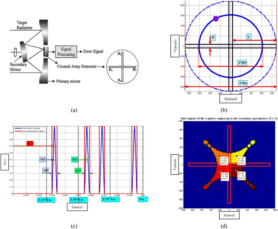
The first system of the pulse position seeker was the cross shape reticle seeker and the CAT seeker (these two seekers are equivalents; in the first one unique detector and a four-slits reticle are used, while four detectors without reticle are used in the second one). The system is a stationary reticle seeker type which employs a fixed reticle, with radius Ra and N=4 transparent slits, and a slightly tilted rotating mirror or lens (with spinning frequency fm) to sweep the target image spot (TIS) along a circular path on the reticle target imaging circle (TIC) with constant radius (RN) [6-8]. The distance of the non-concentric TIC center and its phase relatively to the reticle center define the position of the target in the FOV, as shown in Fig. 1 where: D: the slit width or the detector width. L: the slit length or the detector length. Ra: the reticle radius (FOV radius). For each thermal object the seeker produces four pulses every spinning period. The main problem in this seeker is the small effective area in the FOV, this is because of the non-concentrate or the nutating nature of the seeker which means only 10% of the FOV is effective and the target data can be extracted from the pulses signals [6, 9]. In addition to that, in the present of jammers the threat becomes complex because each object has two pulses for the x-deviation and two for the y-deviation.
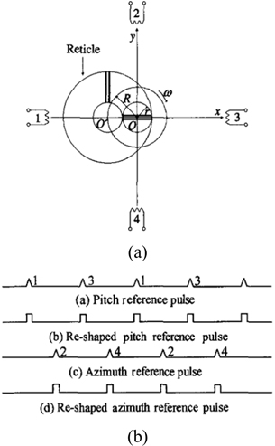
The second system was the L-shape reticle seeker which used only one pulse for x-deviation and one for y-deviation. The merit is in increasing the counter countermeasure ability of it. However, it is so complicated for implementation and still a nutating reticle, as shown in Fig. 2.
III. THE UNIQUE-SLIT RETICLE SEEKER DESIGN
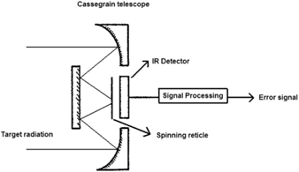
In the first generation of the IR missiles the reticle was a rotating one, as shown in Fig. 3. The main problem was that it was an amplitude-modulated and had no ability for counter countermeasure. Improving this generation was impossible because decreasing the slits number results complex high frequency analog signals. Now, after the appearance of the high speed digital techniques, a rotating reticle can be redesigned to be a pulsed one. This work will get the benefits of the large effective area of the spin reticle and the advanced digital signal processing of the pulsed position reticle nature which will be used in the advanced counter-countermeasure algorithms.
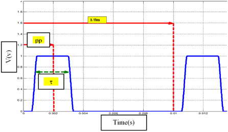
In the previous version of the pulse position seeker the target information is extracted from the pulse position. As this information contains two parameters (r, β ), two pulses at least are needed for each target. In this work the main task is designing the unique slit in a manner that can give all the target information. The design idea is that one parameter is carried by the unique pulse position (pp) and the second is carried by the pulse width (τ ), as shown in Fig. 4.
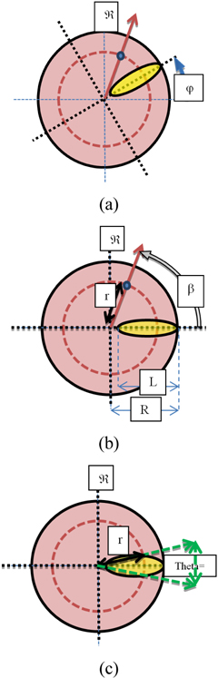
Fig. 5. shows the design parameters: R1: the radius of the starting of the transparent unique slit. R2: the reticle radius (FOV radius). L: the slit length. D: the slit width. φ (t) : the reticle phase in the instant t in the reference ℜ . β (t) : the target phase in the instant t in the reference ℜ . r(t) : the target circle radius in the instant t in the reference ℜ . xT, yT: the target position coordination in the reference ℜ . ℜ : a fixed reference. These parameters take the following values: (D=70, L=850, R1=35, Ra=885) unit or pixel in the general case. The slit is defined by the points:
A function F is defined, which will be called the pattern function and will determine the contour of the slit:
With:
rs∈ [R1, R2]q∈ [θ 1, θ 2]: θ 1 and θ 2 are the limitations of the θ range.
The relation (2) becomes:
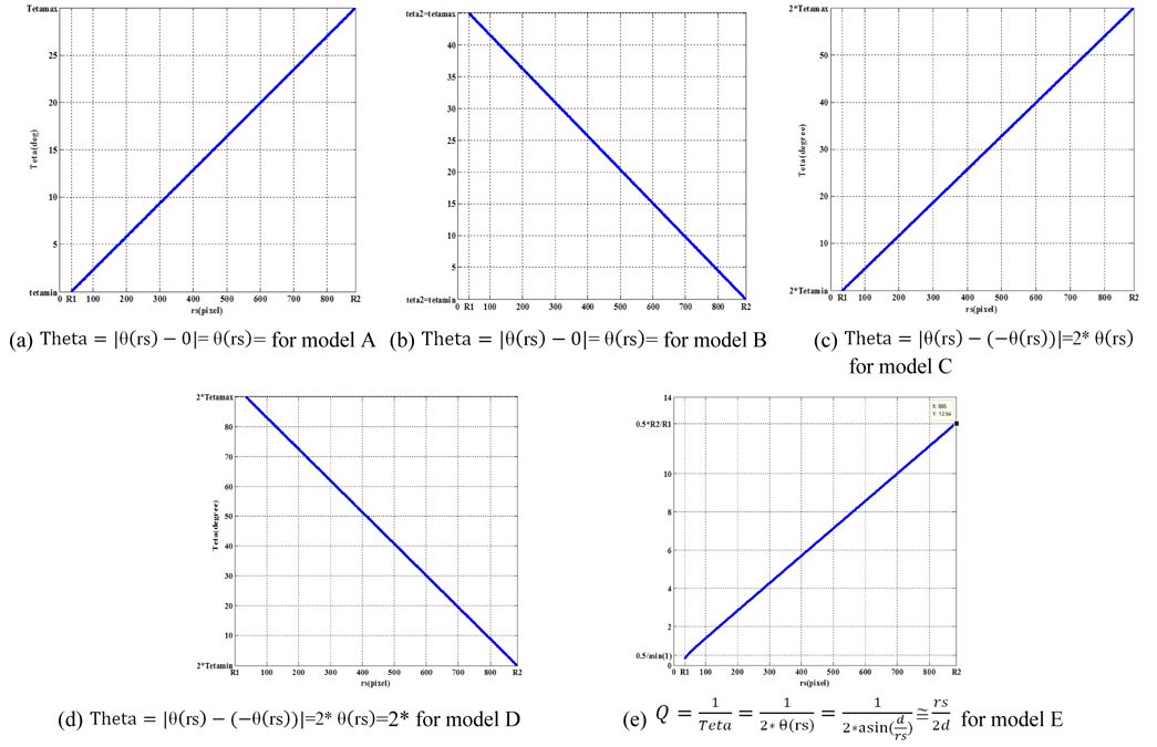
Also Theta, the slit angle at (rs) as shown in Fig. 5 is defined:
As a result, the pulse width resulting from passing the thermal spot of the target (TS) through the slit will be:
And the relation of the detected target position (rd, β d)will be:
where:
rd: the detected target circle radius.bβ : the detected target phase.pp: the pulse position referenced to the spin period (Tm).
It is clear that:
The static gain (SG) function is defined as:
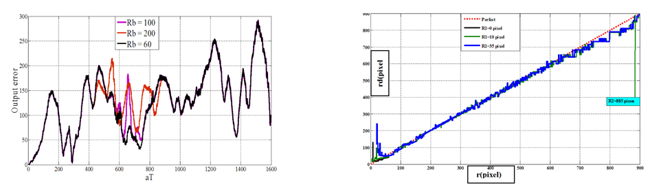
And the radius error function:
So the goal of our design is putting an effective slit pattern function for which the radius error is minimum. In other words, the pattern function has to make the SG function linear on all the reticle area. Also, the G1 function formula has to be defined which has generally simple form.
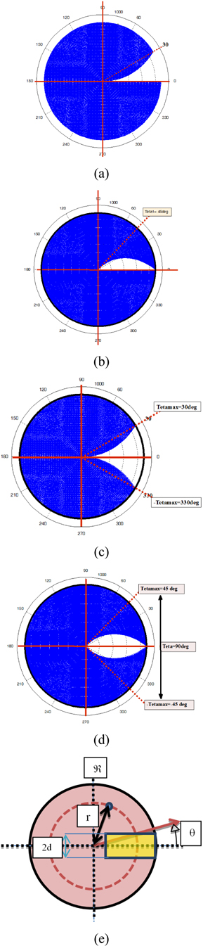
In this model the slit is asymmetric and the pattern function is: Where: θ 1=θ min < θ 2=θmax. Which means that : It is clear that the slit angle (Theta), similarly the pulse width τ , increases linearly with increasing distance from the reticle center. An example for (θ 1=0 deg, θ 2=30 deg) is shown in Fig. 6(a).
In this model the slit is asymmetric and the pattern function is:
Where: θ 1=θ max > θ 2=θ min.
Differently from Model A, the slit angle (Theta), similarly the pulse width τ , decreases linearly with increasing distance from the reticle center. An example for (θ 1=45deg, θ 2=0deg) is shown in Fig. 6(b).
In this model the slit is symmetric and the pattern function is: Where: θ 1=θ min, θ 2=θmax. This means that:
As the model A, the slit is symmetric and the angle (Theta), similarly the pulse width τ , increases linearly with increasing deviation amplitude. An example for (θ 1=0deg, θ 2=30deg) is shown in Fig. 6(c).
In this model the pattern function is:
Where: θ 1=θ max, θ 2=θ min.
This slit is symmetric like model C, and the angle (Theta), similarly the pulse width τ , decreases linearly with increasing distance from the reticle center like the model B. An example for (θ 1=45deg, θ 2=0deg) is shown in Fig. 7(d).
In this model, as shown in Fig. 6(e): The slit is symmetric and the angle (Theta) decreases, but not linearly, with increasing the deviation amplitude. In this model: In this case, it is useful to define the function Q:
3.3. Target Position Detection
The target position detection block has to extract the information which is the target position in the reference plan from the information signal resulting from passing the thermal spot through the slit in one spinning period. This signal which appears on the detector output is a pulsed signal. Each spin period of the information signal contains one pulse for each target in the FOV. The data which have to be extracted is the pulse position (pp) and the pulse width (τ ). And as a result, the detected position data (rd, β d) can be extracted using the functions (G1, G2) as shown in Fig. 4. These functions for each model are stated in Table 1.
[TABLE 1.] The target position detection functions (G1, G2) for the slit models
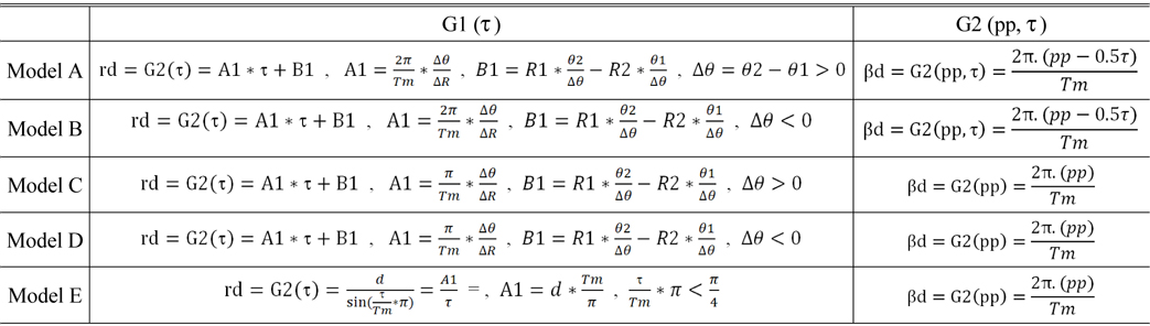
The target position detection functions (G1, G2) for the slit models
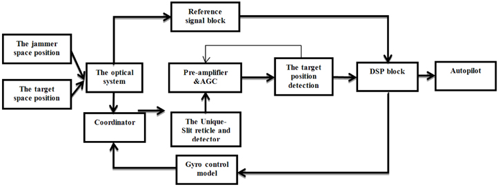
4.1. The Simulation Schematic Block
To evaluate the model design a seeker tracking closed-loop simulation is implemented using MATLAB tools and packages. The target and jammer space dynamic positions are the inputs of the model. The coordinator block processes the previous situation of the reticle plan and the gyro control commends to construct the actual reticle plan which means the relative position of the target and the jammer on the reticle plan. The reticle and the detector block gives the information pulsed signals which carry the FOV data. This signal is amplified by the pre-amplifier; also, it is adjusted to prevent the saturation using the automatic gain control AGC commends. Then, the target position detection block produces the pulses’s data arrays to be processed digitally in the digital signal processing (DSP) block. The DSP block filters the jammer pulses and sends the correction commends to correct the gyro situation to track the real target and the deviation commends to the autopilot. The schematics block diagram of the simulation is shown in Fig. 7.
Using this tool, the SG curves will be gotten and evaluated. In addition to that, the pulse position signal will be stated for several cases.
4.2. The Linearity Area of the Reticle Modes
Increasing the effective area of the reticle area was one of the critical problems in the previous reticles, and it took a large place in the reticle researches [4, 5, 9], because enlarging this area increases the system resistance against noise and perturbations. In addition, it improves the counter countermeasure ability of the seeker [9, 10].
One of the design aims is minimizing the functions (Er, Eβ ), but in the lecture evaluation of the linearity is measured by the linearity of the SG function [3, 4, 6, 9]. In all the models the SG function is totally linear over all the reticle area, as shown in Fig. 8. In all the nutating reticle, like conscan, CAT and L-shape, the effective area is not more than 22% of the reticle surface. However, in the unique-slit spin reticle it is 100%, as shown in Fig. 9.
4.3. The Position Detection Ability
The second important aim of the design is using the pulse techniques, and improving the counter-countermeasure level of the seeker. Each model has merits and demerits from the point of ability of detection and separation targets.
Models A and C have high separation level of targets near the center of the reticle. This merit is important to early jammer detection. However, the targets separation becomes very bad far from the center which limits the tracking of the high speed targets. In contrast, models B and D have low ability of jammer detection which limits the anti-jamming against multi-flares or fast flares.
In models A and B which are asymmetric the phase is determined up to the rising edge of the pulse. This makes the phase independent of the pulse width and more assistance against the active jammer which produces several pulses on the same phase of the real target one. On the other side, this makes measuring the devotion amplitude less accurate. In contrast, in model C and D, measuring the amplitude is more accurate and measuring the phase less.
In models A, B, C and D we have direct linearity; in contrast, the model E need a compensation processing in the DS block. But model E has better characteristics in detecting jammers near the reticle center and far from it.
Several models of rotating pulse-modulated reticle with a unique-slit are introduced and the functions of their patterns are stated. Using a robust simulation tool, the performance of the new design is analyzed and discussed. The results show that the linearity or the effective area of the reticle is better than the previous nutating pulse-modulated reticles, so it is more resistant against noise and aerospace perturbations. In addition to that, decreasing the slits number to one increases the counter countermeasure ability of the seeker as all the deviation data for each target is carried by its own corresponding pulse, so the spatial separation between the real target and jammers using time gates become easier and more effective.