A reflection-type three-dimensional (3D) screen using retroreflector is proposed to improve the visibility of a projected 3D image while keeping its perspective. For the projection-type 2D display, the diffuser is used to represent the 2D scene, overcoming the limitation of the aperture of the projection lens set. If the diffuser is adopted for the projected 3D image, only 2D images sectioned and blurred should be displayed on the screen. The proposed screen can make the 3D image with the aperture limitation visible to be applied to the 3D image projection systems. The feasibility of the proposed screen is verified by experiments.
The projection-type display, called a projector, is a display system using a projection lens set, and is conceptually composed of the light source, the spatial light modulator (SLM) and the projection lens which makes the image of the SLM relocate and resize. The projector is classified according to the types of SLM such as liquid crystal display (LCD), digital mirror device (DMD) and liquid crystal on silicon (LCOS). Since the focal length of a projection lens set can be adjusted simply, the scene size of the projection system is also easy to control from as big as a movie screen to as small as a half inch size. This is the main advantage of a projection system. The projector using DMD represents the gray scale using digital light processing (DLP), which is the expression method of gray scale using the time sharing, and is referred to as a DLP projector. The maximum driving speed of the single pixel of a DLP projector is as fast as 10 microseconds, then the DLP system of which the image has no gray level (only on and off states) can be operated at about 10000 frames per second. Because the extreme conditions for the small pixel size and the fast driving speed are required for the advanced optical systems like 3D display, the projection-type displays are frequently applied to 3D display systems.
The projection-type 3D display systems can be categorized into two kinds; one is the system of which the display part is composed of the projection-type display, and the other is the system which represents 3D images using the projection lens, which is called the 3D image projection system. The projection lens set for the projector, generally, has a restricted aperture size compared with the size of the projected image. Therefore, the whole image cannot be observed directly. The diffusion-type screen which scatters the incident light in all directions should be used to present the whole projected image. The image focused on the screen is observed clearly while the off-focused images are blurred. In the 3D display system using a projector, the diffuser is adopted and modified for the various purposes to represent 3D images. The silver screen for the projection-type stereoscopic 3D display and the spinning screen for the volumetric 3D display are examples of the modified diffuser device for the 3D display system using projector [1-4].
An electro-floating 3D display system can be regarded as a kind of 3D image projection system assuming that a floating lens is a sort of projection lens with a large aperture [5-7]. To observe the projected 3D image directly, the aperture of the projection lens must be large enough compared with the whole size of the 3D image [8]. Otherwise, the represented image will be occluded by the aperture stop of the projection lens for the same reason as for the 2D projection system. However, the diffusion-type screen of the 2D projection system cannot be applied to the 3D image projection system which can represent 3D images with depth and perspectives because the diffuser can only represent the omnidirectional planar images. Thus, a new screen device would be necessary to observe 3D images displayed by the 3D image projection system with a limited aperture, in order to resolve the aperture restriction and represent a volumetric 3D image. In this paper, we propose a reflection-type 3D screen which consists of a lens array and retroreflector film and can be used for the 3D image projection system. We explain how the proposed device can improve the visibility of the projected image which is formed by projection lens set with a limited aperture. The basic experiments are performed to verify the feasibility of the proposed device as 3D screen and the improvement of the proposed device is analyzed quantitatively by measuring the diffusing angle of the image.
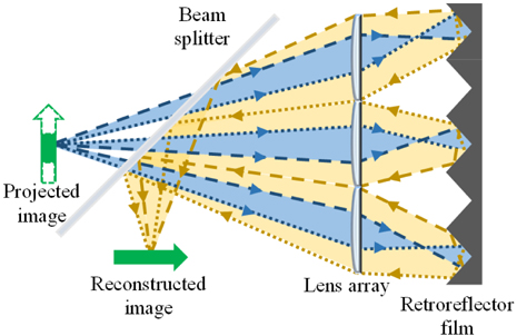
Figure 1 shows the basic scheme of the proposed device. The proposed 3D screen is the simple combination of the lens array and the retroreflector film which is an array of engraved corner cubes that reflects the incident light back to the incident direction [9, 10]. The lens array, of which roles are well known by virtue of integral imaging, consists of elemental lenses whose size is of the order of millimeters and might be smaller than the whole size of the represented image. In Fig. 1, the light ray of the projected image of which the diffusing angle is narrow and expressed by the blue area passes through the restricted aperture of the elemental lens on the lens array. After reflection from the retroreflector, the diffusing angle of the light is widened as the yellow area in Fig. 1. Therefore, the visibility of the image is improved. In previous research, the 3D screen has been proposed and reported using a pair of lens arrays called an optical depth converter, which can improve the visibility of an image with narrow diffusing angle [11]. However, the alignment of lens arrays is very tricky and the viewing angle of the 3D screen using a lens array pair is restricted. The flipped images in the indirect viewing region make observation uncomfortable. The 3D screen using lens array pair can be modified as the reflection-type device using the lens array and mirror, in which the difficulty of alignment can be mitigated.
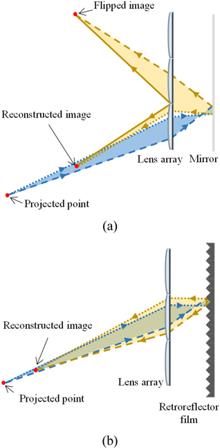
The difference of the reflection-type 3D screen using the mirror and the retroreflector is revealed in Fig. 2. Assume that the 3D images are projected to the proposed 3D screen. The elemental images of the projected 3D images are formed by the elemental lenses in the 3D screen. The viewing angle of the 3D screen using the mirror is limited and the images are flipped because the elemental image reflected by the mirror is spread to several elemental lenses, not only the corresponding elemental lens but also the neighbor elemental lenses as shown in Fig. 2(a). In the mirror case, the reconstructed image is blurred by the flipped image because the gap between the lens array and mirror must be longer than the focal length of the elemental lens in the practical setup. In contrast to the mirror, as shown in Fig. 2(b), the retroreflector can reflect the elemental image back to only the corresponding elemental lens for the proper gap between the lens array and the retroreflector. If the gap is much longer than the focal length of the elemental lens, the flipped image could appear. However, although the flipped image occurs, the direction of reflection is converged back. Therefore, the viewing angle problem can be much moderated compared to other cases.
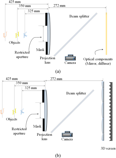
Figure 3 presents the experimental setup of 3D image projection to prove the feasibility of the proposed device. The volumetric 3D images are replaced by the real planar objects, the characters ‘K’, ‘H’, and ‘U,’ which are projected to one of the tested devices by the convex Fresnel lens of which aperture is limited. The tested devices are the mirror, the diffuser, and the proposed device. In other words, this lens with restricted aperture is assumed as the projection lens. The focal length of the projection lens is 152 mm and the aperture size is 64 mm. The characters ‘K’, ‘H’, and ‘U’, all of which are 26 mm, are located at 325 mm, 350 mm, and 425 mm from the projection lens respectively. Each tested device is located on the same position at 272 mm from the projection lens one at a time. The proposed device is composed of the lens array of which elemental lens size is 1 mm and focal length is 3 mm and the retroreflector film of which side of the elemental corner cube is 0.2 mm. The retroreflector film is a product of MN tech, the company whose staple product is Prismatic Retro-reflector sheet [12].
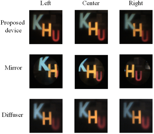
Figure 4 shows the picture results for the experiments of 3D image projection. The first row of Fig. 4 shows the results of the proposed device while the second row and the third row show the results of the mirror and the diffuser respectively. The columns of Fig. 4 present the viewing positions of observer or camera, which represent the perspectives of the reconstructed images. The reconstructed images from the mirror, as shown in Fig. 4, show the perspectives, which means that the reconstructed images are changed due to the observing positions. But, the whole characters cannot be observed from the mirror because of the aperture limitation of the projection lens. Meanwhile, in the case of the diffuser, whole characters can be observed, but the reconstructed images are the same in all viewing directions, which means that there are no perspectives and the represented images are not 3D, but 2D. Moreover, only the character ‘H’ located on the diffuser is clear while the off-focusing characters ‘K’ and ‘U’ are blurred a little.
The reconstructed images of the proposed device shown in the first row of Fig. 4 show the merits and the features of the proposed device. The entire characters can be observed from the proposed device with inverted perspectives compared with the cases of the mirror. The spaces between the characters in the mirror become narrow toward the left while those in the proposed device present in reverse, which means the images of the proposed device are the pseudoscopic images. This pseudoscopic phenomenon tells us that the perspectives of projected 3D image in the proposed device are preserved by the pickup and reconstruction process of integral imaging.
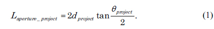
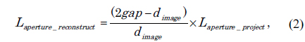
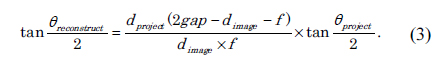
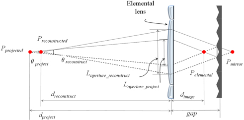
As mentioned above, the proposed device can resolve the aperture limitation of the projection lens. The aperture limitation can be calculated as the diffusing angle of the lights. The small aperture stop of the projection lens sets off the small diffusing angle of image and produces the limitation of observation. The visibility improvement of the proposed device can be analyzed quantitatively by measuring the change of the diffusing angles of image. Figure 5 shows the schematic diagram to calculate the increment of diffusing angle in the proposed device. For convenience of calculation, the object and the projection lens system are not considered. Assume point

The elemental image of the projected image,

where

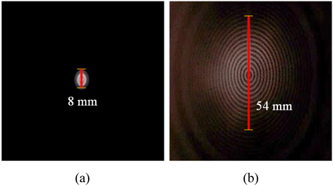
The increment of diffusing angle can be measured by simple experiments. The scheme of experiments is almost the same as for Fig. 3, except for the concentric circle target image instead of the 3D objects and the small aperture size of the projection lens of which the diameter is 8 mm. The target image is located on 304 mm while the proposed 3D screen is located on 312 mm from the projection lens. In experiments,
In this paper, we propose the reflection-type 3D screen using retroreflector to improve the visibility of 3D images with aperture limitation. In the proposed device, the 3D effects such as the perspectives are preserved through the process of integral imaging and the diffusing angle is increased in virtue of the retro-reflection effect. Using the proposed device, the 3D image can be represented through the projection lens with a small aperture. In other words, we can make a large scene from small volumetric 3D images, which can be represented by light field 3D displays such as integral imaging and holography. To apply the proposed device in the projection system, the pseudoscopic phenomenon must be considered and concerned. But, these characteristics might be exploited to resolve the pseudoscopic effect of image representation. For example, the proposed device can directly be applied to the projection-type integral imaging system in real display mode whose elemental image is obtained by a real pickup process, where the pseudoscopic problem occurs. The proposed 3D screen can be used to accomplish a large-size wide-viewing 3D projection display system such as glass-free 3D TV and 3D Movie Theater.