We present design and fabrication of a multi-focusing microlens array (MLA) using a thermal reflow method. To obtain multi-focusing properties with different numerical apertures at the elemental lens of the MLA, double-cylinder photoresist (PR) structures with different diameters were made within the guiding pattern with both photolithographic and partial developing processes. Due to the base PR layer supporting the thermal reflow process and the guiding structure, the thermally reflowed PR structure had different radii of curvatures with lens shapes that could be precisely modeled by the initial volume of the double-cylinder PR structures. Using the PR template, the hexagonally packed multi-focusing MLA was made via the replica molding method, which showed four different focal lengths of 0.9 mm, 1.1 mm, 1.6 mm, and 2.5 mm, and four different numerical apertures of 0.1799, 0.2783, 0.3973, and 0.4775.
Recently, optical systems using microlens arrays (MLAs) have been intensively studied for a variety of applications that include optical communication systems [1-2], confocal optical microscopy [3-4], and 3-dimensional (3-D) imaging systems [5-7]. Particularly in integral imaging systems that have been studied for 3-D displays providing autostereoscopic images with full parallaxes, the 2-dimensional (2-D) MLA is an essential optical element to record 3-D information about an object on a charged-couple device (CCD) [8-9] and to display 3-D images. However, with conventional MLAs, which have the same focal length at each elemental lens, the depth of field available for capturing 3-D objects or for displaying 3-D images is highly limited in 3-D integral imaging systems [10-13]. When we reduce the numerical aperture (NA) of the elemental lens of the MLA to improve the depth of field, the spatial resolution of the integral imaging systems is inevitably degraded. To achieve a large depth of field without spatial resolution degradation, a time-multiplexed integral imaging method utilizing MLAs with different focal lengths has been theoretically proposed [12].
There are several methods for fabricating MLAs, such as ink-jet printing [14], lithographic patterning methods using an electron beam [15], a proton beam [16] or an ion beam [17], and thermal reflow methods [18-23]. In thermal reflow methods, photoresist (PR) cylinder structures made by photolithography are melted by thermal energy above the glass transition temperature of the PR. After the reflow process, the shape of the PR structure is converted to a hemispherical lens profile in order to minimize surface tension, where the lens profile depends on the surface critical angle between the substrate and the PR. The critical angle can be controlled by introducing a buffer layer under the PR structure, which changes the surface energy between the substrate and the PR [20]. However, it is very difficult to fabricate MLAs with different focal lengths by utilizing the different critical angles in one substrate because the surface energy of the substrate should be patterned precisely. In addition, the surface energy is highly dependent on temperature, but the thermal reflow method requires a hightemperature process, in general.
In this paper, we present design and fabrication of a multi-focusing MLA by using the thermal reflow method. By controlling the initial volumes of the double-cylinder PR structures that are formed within the guiding patterns, the radii of curvatures, the focal lengths, and the NAs of the elemental lenslets for the multi-focusing MLA can be precisely designed and fabricated. First, the fabrication process for the PR template and the replicated multifocusing MLA will be introduced. Then, we discuss an analysis of the relation between the initial volume of the double-cylinder PR structure before the thermal reflow process and the lens properties of the multi-focusing MLA (such as radius of curvature, focal length, and NA) replicated from the thermally reflowed PR structure.
II. FABRICATION OF MULTI-FOCUSING MLA
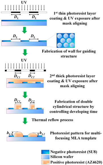
Figure 1 shows the fabrication method of the template structure for the multi-focusing MLA with the photolithography process and the thermal reflow process. In our experiment, a thin negative tone PR (SU8, MicroChem Co. Ltd.) layer was spin-coated on a silicon wafer and patterned to the hexagonal hole array for the guiding wall structures, where the thickness of the PR layer was 10 μm, the periodicity of the hexagonal hole array pattern was 650 μm, and the diameter of the hole structure was 600 μm. The wall structure for the hexagonal hole array, made with the negative tone PR, was cross-linked by ultraviolet (UV) light irradiation, which enabled it to maintain its structural integrity during the subsequent photolithography and reflow processes. On the hexagonal hole array pattern, a thick positive tone PR (AZ4620, AZ Electronic Materials Co. Ltd.) layer was spin-coated and prebaked to remove solvent. These PR coating processes and the prebaking process were repeated four times to form a thick PR layer of 80 μm thickness. The sample was aligned with the photomask and exposed to the UV light. The photomask was designed to have hexagonally arrayed circular patterns with four different diameters:
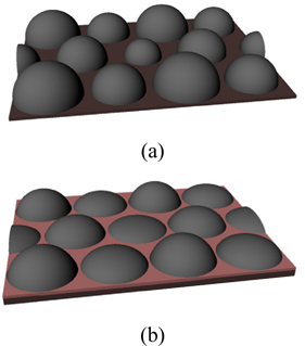
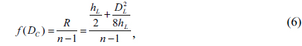
Figure 2 shows schematic illustrations of the multi-focusing MLAs made by the thermal reflow process. Figure 2(a) shows the thermally reflowed result without the guiding wall structure and without the base layer that is used in Fig. 2(b) to promote diffusion of the PR. In this case, the lens shapes are determined by the critical angle between the substrate and the PR. Therefore, it is hard to obtain an MLA that has an elemental lenslet array with precisely controlled different NAs in the same substrate. Because the lateral diffusion of the PR is limited by the relation between the initial PR volume and the critical angle on the surface, the diameters of the elemental lenslets are different from each other, the fill factor of the multi-focusing MLA is low, and the periodicity of the elemental lenslets cannot be controlled precisely. However, with the guiding wall structures and with the base PR layer, the diameter of the elemental lenslet can be precisely controlled, as shown in Fig. 2(b). The radius of curvature and the NA of the elemental lenslet can also be controlled and predicted by the volume of the PR structure before the thermal reflow process.
Figure 3 shows the reflective optical microscopic images of the hexagonally arrayed PR structures after the developing process (Figs. 3(a) and Figs.3(c)) and after the thermal reflow process (Figs. 3(b) and Figs.3(d)), where the PR structures for each elemental lens are denoted as L1 (
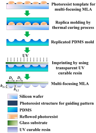
Figure 4 shows schematic illustrations of the fabrication process for the multi-focusing MLA replicated from the thermally reflowed PR template structure. First, the surface profile of the thermally reflowed PR template was replicated by using polydimethylsiloxane (PDMS) which is generally used for soft lithography owing to its conformal contact property and low surface energy. The PDMS block on the PR template was thermally cross-linked on a hot plate at 70℃ over 5 hours. After detaching the PDMS mold, the reverse pattern on the PDMS was used for the multi-focusing MLA pattern on a glass substrate. For the transparent lens material, a UV curable photopolymer (NOA89, Norland Products Inc.) was used. Finally, the multi-focusing MLA was made via the UV-imprinting process, which had the same surface profile as the thermally reflowed PR template structure.
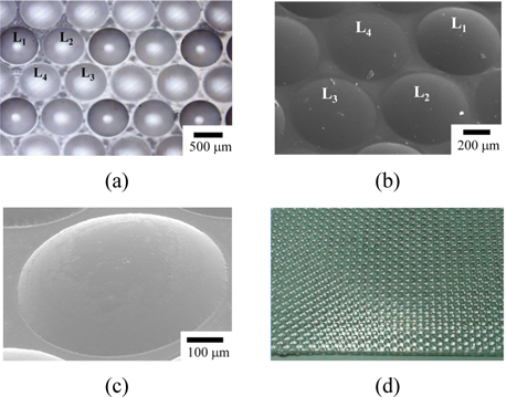
Figure 5(a) shows the reflective optical microscopic image of the PDMS mold surface, which has four different concave radii of curvature replicated in reverse from the thermally reflowed PR template. Figures 5(b) and (c) show the scanning electron microscope (SEM) images of the multi-focusing MLA on the glass substrate that was reversereplicated from the PDMS mold by using the UV-imprinting process. All elemental lenslets (L1, L2, L3, and L4) of the multi-focusing MLA showed ideal hemispherical lens profiles owing to the complete filling of the melted PR within the guiding wall patterns during the thermal reflow process. Figure 5(d) is a photograph of the multi-focusing MLA sized to 3×3 cm2 . The fill factor of the multi-focusing MLA we fabricated was 0.7727. With our method, the fill factor of the MLA can be increased by reducing the width of the guiding wall structure. To improve the spatial resolution of the 3-D integral imaging system, the periodicity as well as the position of the elemental lenslets can also be easily optimized.
III. ANALYSIS ON MULTI-FOCUSING MLA
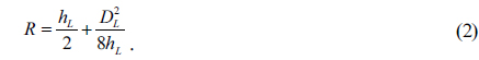
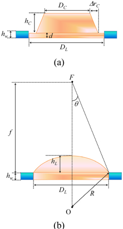
The focal length of each elemental lens of the multifocusing MLA can be precisely designed by controlling the initial volume of the double-cylinder PR structure, which is defined by the transmission aperture of the photomask. Figure 6(a) shows the cross-sectional PR structure before the thermal reflow process, where the PR structure has the modified shape from the double-cylinder structure to a truncated cone shape on the thin cylinder structure considering the partial developing effect on the thick positive tone PR layer. The diameter of the top surface of the truncated cone structure is denoted as
where

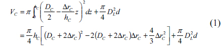
We assume that the melted PR is completely filled within the guiding wall structure as shown in Figs. 5(b) and Figs.5(c). From Fig. 6(b), the total volume of the hemispherical lens and the underlying cylindrical structure within the guiding wall is expressed as follows:

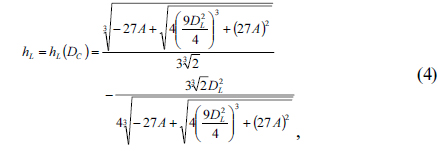
Neglecting the volume change before and after the thermal reflow process, from equations (1) and (3), the height of the elemental lens structure can be expressed as a function of

where

Note that
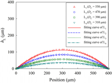
We measured the surface profiles of the multi-focusing MLA by using a contact type surface profilometer, as shown in Fig. 7.
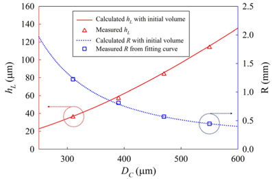
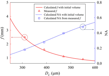
Figure 8 shows the calculated and measured
The focal length of the elemental lens is described by using the radius of curvature as follows:

where
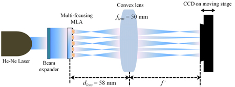
In order to measure the focal lengths of the multi-focusing MLA, the experimental setup shown in Fig. 9 was used. The calculated focal lengths were too short, and the focal length differences between the elemental lenses were also too small to directly measure the focal lengths of the multifocusing MLA. Therefore, a convex lens (
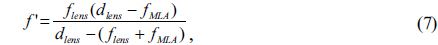
where
We also checked the NAs of the multi-focusing MLA from the measured focal length. The NA of the spherical lens is calculated as follows:

where θ is the angle seen in Fig. 6(b). The calculated NAs of the multi-focusing MLA, by using equations (2), (4), (5), and (6) and the
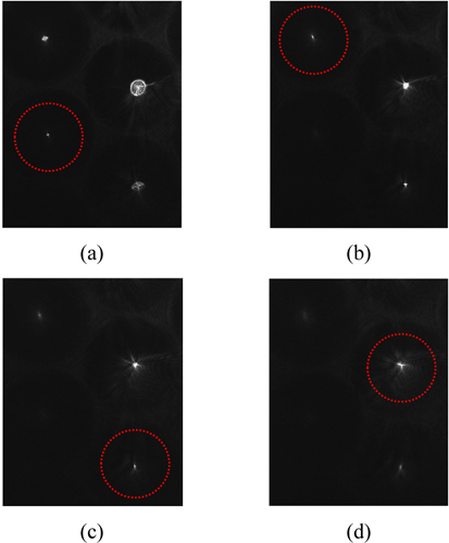
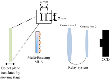
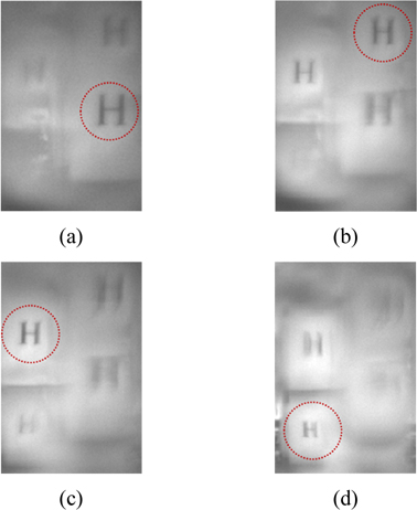
Figure 12 shows the experimental setup for capturing the object image by using the multi-focusing MLA. As an object, the English upper case letter “H” printed on a piece of paper was used. The size of the character was 4×7 mm2. Figure 13 shows the CCD images captured by the L1, L2, L3, and L4 elemental lenses of the multi-focusing MLA, which were obtained as the object plane moved away from the position of the multi-focusing MLA. At different object distances, a clear image was obtained with a different elemental lens, which means that image capture with enhanced depth of field can be obtained by utilizing the time-multiplexed moving MLA scheme [12].
We present a fabrication method for a multi-focusing MLA by using the thermal reflow method. By using the guiding wall pattern, the radius of the curvature for the reflowed PR structure could be precisely predicted from the photo-lithographically defined PR volume. In addition, by introducing a thin base PR layer using the partial developing method, the ideal lens profile could be obtained with completely filled PR structures within the guiding wall patterns during the thermal reflow process. Due to the partial developing method, the photo-lithographically patterned PR structure was modeled with a truncated cone structure on the thin-cylinder structure, not with the simple doublecylinder structure. By using the proposed method, lens properties such as the arrangement, pitch, diameter, radius of curvature, focal length, and NA of the elemental lens of the multi-focusing MLA can be precisely designed and fabricated, which can be usefully applied to several 3-D optical systems.