Engineering of light-matter interactions at nanoscale dimensions has been acknowledged as one of the primary branches of optical physics, and it has been verified that the strong interaction of an incident light with noble metal nanostructures at a certain optical frequency causes generation of surface plasmon resonance (SPRs), which correspond to the coherent oscillations of free electrons in the conduction band of the utilized subwavelength structures [1-6]. It is verified that the plasmonic properties of the metal structures in nanoscale can be characterized by classical electromagnetic theory, which provides analogous behavior to the atoms’ and molecules’ wave functions [7, 8]. On the other hand, near-field coupling between closely adjacent or neighbor nanoparticles has been considered as one of the important subfields of plasmonic notions [9-14]. Conventionally, robust plasmon resonance coupling can take place in adjacent metal nanoparticles which are known as a dimer, and a pair of particles is the simplest example of these nanostructures [15-18]. Prodan et al. [7] proved that locating two nano-particles in close proximity causes mixing and hybridization of their plasmon resonance modes which leads to formation and observation of bonding bright and antibonding dark modes. In addition, Liu et al. [19] showed that a plasmon hybridization model can be employed in analyzing plasmon resonance modes of multicomponent structures and clusters that consist of sophisticated structural configurations. In this case, Fan et al. [20] confirmed that a cluster composed of seven similar and proximal nanoparticles which are situated in a close and equal distance from each other is a simple heptamer that has the structural symmetry of a benzene molecule. Moreover, it is shown that due to the strong interferences of subradiant and super-radiant plasmon resonance modes, Fano-like resonance dips can be observed in the spectral response of these structures [21, 22].
Plasmonic nanostructures based on metallic nanoparticles have extensively been utilized in designing all-optical devices, which gives us opportunity to manipulate the plasmon resonance modes at particular frequencies [23-29]. Most of associated works prove that significant losses and dissipations appear during guiding of optical waves during electric plasmon propagation, and these destructive components cause dramatic limitations in the propagation distance. Liu et al. [8] showed that magnetic plasmon modes can be guided and coupled through a chain of nanorod heptamers which are configured in chrysene and triphenylene structures with large decay distance of propagated fields. On the other hand, several attempts have been made on different nanoparticles to provide more geometrical versatility to enhance the quality of optical power propagation. Nanoshell has widely been employed to design nanostructures because of its strategic structural features and ability to operate properly at NIR [12, 22, 23]. Several optical devices such as, couplers [12], optical energy splitters [23, 24], and hybrid polarization beam splitters (HPBS) [25] have been designed and fabricated based on nanoshell arrays which are able to work at the telecom spectrum efficiently. Ahmadivand et al. [23,24] verified that T and Y-shape optical power splitters in various forms can be designed by ordered arrays of nanoshells with specific geometrical sizes. This kind of splitters is able to separate and divide the incident and guided light into two identical parts and steer it along the output paths such as two-branch (1×2) and four-branch (1×4) splitters. Limitations in decaying length of the guided electromagnetic (EM) waves and low coupling strength at sharp corners and angles are some of the crucial destructive factors which affect the configuration performance noticeably [32, 33]. It is well-known that the shape, material, and size of the metal nanoparticles play a fundamental role in designing an efficient plasmonic device. Therefore, an appropriate orientation of employed nanoparticles would be helpful to provide enhanced coupling and guiding of plasmon resonance modes.
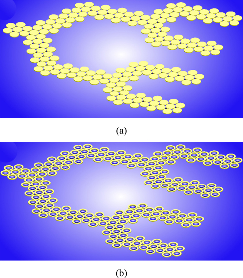
In this article, we employ Au nanoshells with Johnson-Christy constants to design heptamer clusters that are oriented in triphenylene molecular orientation [30, 31]. Utilizing the triphenylene structure and also extending the number shell heptamers in triphenylene molecular orientation, we designed a long range and efficient 1×4 Y-shape optical power splitter. Offset distance as a key part in designing of this device has been tailored numerically and the results presented. Finite-difference time-domain method (FDTD) as a simulation tool is used in our numerical approach to calculate the unique behavior of these proposed structures [34, 35]. Finally, we compare the optical properties and performance of our proposed nanoshell-based structure with an analogous splitter based on rod particles in the same orientation.
The rest of this work is organized as follows: In Section 2, the optical characteristics and plasmonic coupling modality between nanoshell and nanorod heptamers which are oriented in a triphenylene structure have been investigated numerically. Using the results of the accomplished modifications on the shells and rods dimensional sizes regarding to the extinction spectra and plasmon coupling intensity, we provided an efficient artificial blueprint of the shell heptamers to operate at the telecommunication spectrum. In Section 3, we studied the proposed 1×4 Y-splitters based on the examined heptamers composed of rods and shells that are situated as a triphenylene configuration. The optical properties of both of the splitters have been evaluated and the efficient and preferred solution is introduced.
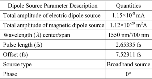
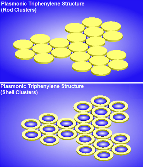
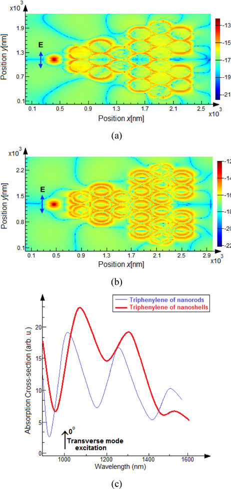
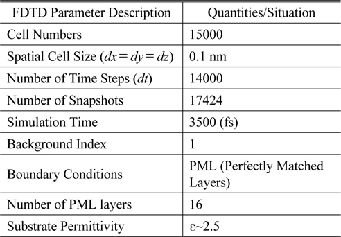
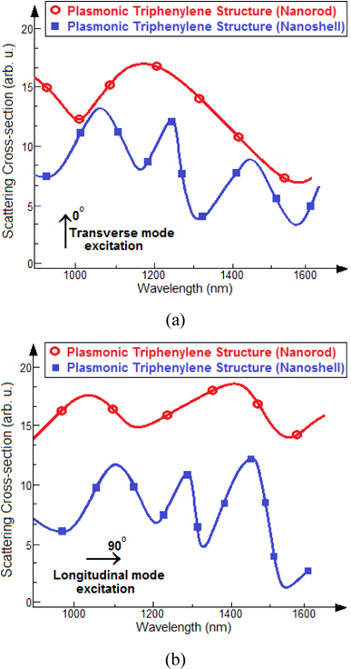
In this section, the optical properties of Au nanorods and shells which are ordered as a triphenylene configuration are investigated briefly. First, we examine two traditional Au nanoparticles for heptamer structures to provide an accurate cluster that can be exploited at the telecommunication spectrum (λ~1550 nm). Figure 1 demonstrates the schematic diagram of the triphenylene nanostructure based on rod and shell heptamers. All of these particles are embedded in a glass host with a permittivity of ε~2.5. Considering structural modifications in the adjacent clusters, we evaluated the plasmon resonance and extinction spectral profile for this structure. To do this, an electric dipole source with transverse polarization direction has been applied which is located at 2R away from the first nanoparticles of the main heptamer (left heptamer). By locating plasmon resonance position at λ~1550 nm, based on the geometrical sizes of rod and shell particles, this distance is determined as 252 nm and 235 nm for rod and shell particles, respectively. Jung et al. [12] proved that the Au nanoshell is the appropriate nanoparticle to operate at the NIR region effectively. On the other hand, Ahmadivand et al. [23] showed that Au nanorod is not an appropriate particle for NIR applications due to its destructive far-field scattering and absorption ratios. Figure 2(a) illustrates a comparative diagram for the proposed orientations based on mutual heptamers, which evaluates the extinction cross-sectional profile for two different plasmonic triphenylene structures composed of Au nanoparticles. Obviously, two minima dips (at λ~1000 nm and 1500 nm) have appeared along the extinction spectra for plasmonic Au nanorods heptamers in triphenylene structure (the dimensions of the rod are: height=40 nm and radius=126 nm) [8]. Here, the shorter wavelength is due to the Fano-like resonance effect and the longer one is allied to the plasmon resonance. Noticing in this figure, also, we calculated the extinction cross-sectional diagram for the proposed shell heptamers in a triphenylene structure, and as a result, we observed four minima dips for the shell heptamers at λ~940 nm, 1180 nm, 1340 nm, and 1570 nm (the dimensions of the shell are: height=40 nm and outer radius=122.5 nm, inner radius=90.5 nm) [23, 24]. Two shorter wavelengths are due to the Fano-like resonances, and two larger ones correspond to the plasmon resonance which occurred around the telecommunication wavelengths. All of the diagrams have been calculated for the transverse electric incident field. Figure 2(b) demonstrates the quality of Fano-like and plasmon resonances for both of the prior plasmon triphenylene structures under longitudinal incident field excitation, however, extracted results have shown approximately the same minima positions for both of the modes, and the Fano-like dips have been observed at nearly the same wavelengths for both of the incident dipolar modes. The quality of surface plasmons (SPs) excitation and resonance coupling between mutual and proximal nanoparticles through the triphenylene structure based on rod and shell heptamers under transverse electric polarization mode are illustrated by two-dimensional snapshots in Figs. 3(a) and 3(b), respectively. Simulation results show that the plasmon resonance coupling in both of the structures has been attained in an anti-ferromagnetic coupling regime which lies at the telecom spectrum. The polarization direction and location of the incident light is indicated inside the picture, and the direction of the arrow demonstrates the transverse mode distribution along the shell and rod clusters. Here, it should be noted that the excitation of SPs is in the circular anti-phase mode for four arranged Au rod and shell heptamers. Moreover, it is acknowledged that in the same method as analogous spherical rod heptamers, the charge density propagates along the shell heptamers in “anti-ferromagnetic” plasmon modes [13, 28]. Additionally, Fig. 3(c) evaluates the absorption spectrum for both nanorod and shell plasmonic triphenylene structures which provides more insight for the proposed configurations. Clearly, utilizing an electric dipole source causes to expose the resonances as absorption extremes at the desired wavelengths (plasmon resonance minima), and the amplitude of the absorption cross-section at these points are considerably more than scattering spectra. Comparison between rod and shell absorption cross-sectional diagrams proves the dominant behavior of the nanoshells heptamers at the telecom spectrum due to its lower ratio of optical power absorption than for rod ones. Table 1 includes all of the FDTD settings and parameters descriptions that have been utilized in extracting the optical properties and plasmon response of the proposed nanostructure. In addition, we listed the parameters and settings of the employed dipole sources in Table 2. In this set of numerical calculations, perfectly matched layers (PMLs) have been set as boundary conditions for all of the three dimensional axes (x, y, and z). Accordingly, these layers provide dramatic absorption of scattered electromagnetic fields which prevent the interference of guiding and scattering fields in the workplace. Also, due to the small gap distance between proximal nanoparticles as well as mutual heptamer clusters, we have set the spatial cell sizes for dx, dy, and dz to 0.1 nm, and as a result, highly accurate spectral responses have been obtained numerically. Moreover, in all of the splitter investigations, the central particle of the main heptamer has been removed and the dipole source is located instead. In this method, we would be able to propagate the optical energy efficiently along the structure composed of closely spaced heptamer clusters.
In this section, we demonstrate a new application of Au rods and shells heptamers which are oriented in a triphenylene structure. Figure 4 shows the schematic diagram of a Y-shape splitter which includes an input port and four output ports (1×4 Y-splitter). The most important point here is that due to the symmetry in physical configuration of the proposed Y-splitters composed of rod and shell heptamers, the momentum of the electric dipole of an incident magnetic plasmon resonance is insignificant and almost zero, which verifies the dark mode existence in this guidance regime. In addition, it has been strongly verified that that elucidated dark mode is extremely infrequent during utilization of a plane wave source in normal mode, which corresponds to the deviation of the employed nanoshells and rods sizes in all of the arranged heptamers [8, 31]. Here, we applied this mode in FDTD simulation settings, especially when using the electric dipole source which includes localized fields. Considering investigated plasmonic triphenylene structures composed of rod and shell heptamers and extending the number of clusters in the propagation direction (x-axis), we designed the final structures as Fig. 4. Then we compared the advantages of each one of the proposed splitters that contain 40 shell and rod heptamers, individually. It is noteworthy that like analogous heptamers of spherical particles, the charge density propagates along the heptamers in “anti-ferromagnetic” plasmon modes, and due to the presence of the dark mode, the energy of the propagated electric field reduces remarkably [13, 28]. Therefore, employing a magnetic dipole source, we would be able to study the new and interesting aspects of magnetic plasmon modes through the proposed devices which can be manipulated based on magnetic plasmon waveguides.
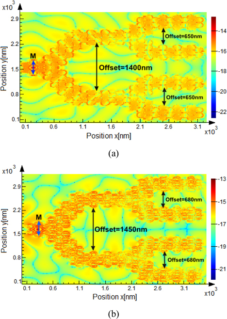
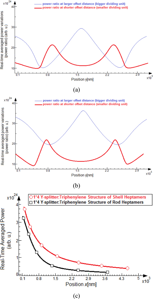
Continuing using the mentioned magnetic dipole sources which are indicated by arrows in Figs. 5(a) and 5(b), the magnetic field is distributed along the plasmon waveguide by coupling between shared or mutual particles of the heptamers in both 1×4 rod and shell-based Y-splitters. These depictions are two-dimensional (xy) snapshots that are calculated numerically. The center heptamer in both of the nanostructures is considered as a main port which guides the optical power to both branches of the splitter. Also, the central particle of this heptamer has been removed, and the incident field placed instead. Noticing in Figs. 5, the circular fluxes of dipoles originates from the main cluster of nanoshells and rods, then divides by two adjacent heptamers, and propagates though the straight branches until the next separating sections. This location of both of the structures functions in a similar method to the first splitting section. Consequently, the transmitted optical power is being divided to four approximately identical amounts of optical energy. It is shown that the ratio of the propagated optical power at the output ports is the most important parameter in various kinds of splitters which defines the quality and performance of the recommended nanostructures [23, 24]. Also it is proved that in order to calculate the ratio of transmitted power through a structure, a complex Poynting vector as and the real-time averaged power variations over the distance or in the splitting axis (y-axis) must be employed concurrently (Figs. 6(a) and 6(b)). Thus, considering the magnetic power flux in a specific direction and also, the time-averaged magnetic power flowing across a surface by then the ratio of the transmitted power can be determined by calculating the proportion of the monitored power at the last heptamers (rod and shell) with respect to the incident amount of power [23, 24]. Consequently, the ratio of transmitted power for the 1×4 Y-splitters based on rod and shell-based heptamers are 22.2% and 23.9%, respectively. These quantities show that the ratio of the transmitted and observed power at the output of each one of the branches of the splitter composed of shell heptamers is more than the other structures (rod heptamers). This difference in power ratio originates from the nanoshell geometrical versatility and compatibility at λ~1550 nm in comparison to rod particles. Moreover, we demonstrated that the ratio and impact of extinction components are highly dramatic in Au rod-based heptamers, in contrast, the ratio of the absorption and dissipation factors in Au nanoshell heptamers are lower at the desired telecom spectrum.
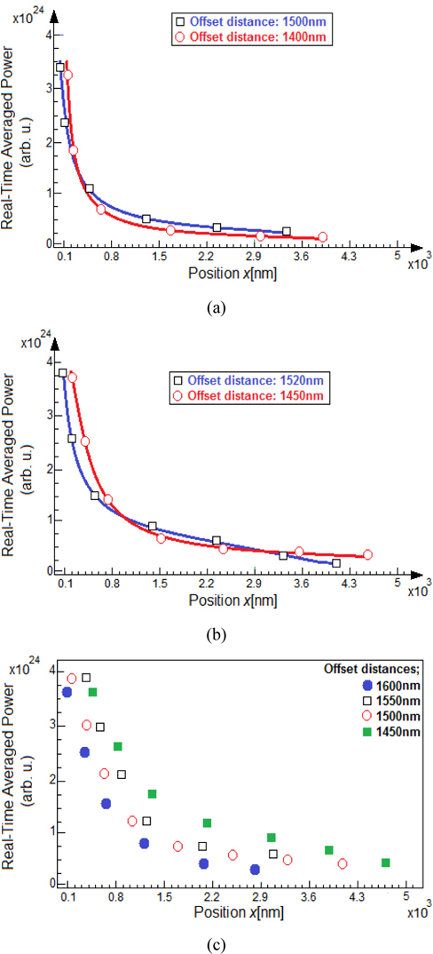
Owning a large decay distance of optical power along a plasmonic nanostructure is one of the prominent purposes that can be improved by using more complex configurations and accurately adjusted nanoparticles. Therefore, considering studied structures, we would want to quantify and evaluate the decaying length of the propagated and coupled magnetic plasmon resonance along the branches (propagation direction in the x-axis for both of the splitters). Noticing in Fig. 6(c), the decaying length at all of the splitter’s branches are equal like the power ratio and are approximately 3.8 μm and 4.4 μm for nanorod and nanoshell heptamers, respectively. Considering the depicted diagram, the decaying length of both of the investigated artificial configurations are considerably longer than rudimentary four-branch splitters that are based on electric plasmon coupling and propagating which include destructive interferences (maximum ~2.5 μm) [23, 24]. On the other hand, evaluating the two latest examined nanostructures, the decaying length of the plasmon waveguides based on the shell heptamers are interestingly more than rod clusters.
For the final examination, we measured the effect of offset distance (splitter arm spacing) as a significant parameter on the operation quality of the proposed device. Ahmadivand et al. [23, 24] proved that the offset distance between splitter arms plays a fundamental role in the quality of the structure. Accordingly, minor modifications in this parameter lead to dramatic alterations in the decaying length of the structure. The corresponding offset distances for each one of the structures are indicated through the prior snapshots (Fig. 5). Simulation results reveal that reducing this size of arm spacing causes increments in power ratio and also, the decaying length of the guided waves. However, this reduction must be controlled, because more reductions in the offset size lead to negative interferences between guided magnetic EM waves at parallel branches. The optimal and final offset sizes for proposed structures are 1400 nm and 1450 nm for the biggest dividing unit and 650 nm and 680 nm for the smallest dividing units for rod and shell heptamers, respectively (indicated in Figs. 5). Figures 7(a) and 7(b) illustrate the influences of offset distance variations on the decaying length for both of the examined splitters. Accordingly, increasing the size of main arm spacing (the main splitting section) in both of the nanostructures causes reduction in decaying length, as we expected. Consequently, finding and tuning this parameter would help to provide a device that has a possible maximum decay length with lower dissipative and light scattering effects at λ~1550 nm. Figure 7(c) evaluates the effect of variations in the offset size on the optical response and the quality of the splitter, while the smaller offset distance is 680 nm. Accordingly, on reducing the offset distance of the shell nanoparticle-based splitter from 1600 nm to 1450 nm, a dramatic enhancement in the decaying length of optical energy is observable. More reduction directly causes robust destructive interference of guided waves of the splitters’ branches.
In this work, we studied the magnetic plasmon resonance coupling and guiding through the nanorod and shell heptamers arrays ordered in a triphenylene structure. Extending the number of proposed nanoparticles clusters, we designed a long-range and enhanced 1×4 Y-shape splitter to employ at the telecom spectrum. To provide exact results, we evaluated the spectral response of the two similar configurations composed of two different nanoparticles (rod and shell) clusters in triphenylene molecular fashion. Therefore, we calculated the plasmon resonance quality and the influence of lossy components on the splitter performance at the telecom spectrum (λ~1550 nm). Simulations results proved that the splitter based on shell heptamers shows efficient behavior during magnetic plasmon resonance propagation along the structure with 23.9% power ratio at each one of four branches, the decay length of 4.4 μm, and 1450 nm offset distance. The effects of dissipative and lossy factors on the device operation have been investigated numerically based on an FDTD method. Ultimately, we proposed an enhanced structure composed of Au nanoshell heptamers that is able to provide longer optical power propagation at the desired spectrum with lower impact of losses. This work opens new paths to utilize recommended theory in designing various efficient plasmonic devices that are able to function at the NIR efficiently.