검색 전체 메뉴
PDF
맨 위로
OA 학술지
Color-Matching Liquid Crystal Display using a Lenticular Lens Array and RGB Light Sources
  • 비영리 CC BY-NC
  • 비영리 CC BY-NC
ABSTRACT
Color-Matching Liquid Crystal Display using a Lenticular Lens Array and RGB Light Sources
KEYWORD
LCD , High efficiency , Color matching
  • I. INTRODUCTION

    The major issues of future liquid crystal displays (LCDs) will be energy efficiency and image resolution, as LCDs become larger and consume more energy in proportion to size. The resolution issue has been already addressed very well by employing the ultra-high definition (UHD) format that has twice the pixel density of the current full high definition (FHD) format, and it seems that there remain no serious technical problems [1]. However, concerning energy efficiency there is no clear solution so far, although there have been many efforts to increase efficiency. The typical light transmittance of the LCD panel remains as low as about 5%, mainly due to absorption in the polarizer and color filter (CF) of the LCD panel. The effort to improve energy efficiency includes three approaches. The first is developing a polarized backlight that illuminates the liquid crystal panel (LCP) with polarized light, to avoid absorption by the bottom polarizer [2-4]. The second is using field sequential color (FSC), a time-domain multiplexing technology to enhance the transmittance of the LCP by removing the color filter [5]. This technology is especially attractive because it can enhance the light energy efficiency as well as the removal of subpixels of the LCP and color filter. Despite many efforts, however, it turned out that the color breakup problem is very hard to overcome, and most technologies to reduce the color breakup in FSC images have not been successful [6]. The third approach to enhance energy efficiency is using a color-matching technique that utilizes a three-color backlight to match the RGB subpixels of the color filter [7, 8]. Yamada et. al proposed a color-filterless LCD employing an edge-lit backlight that belongs to the spatial-domain multiplexing technology [9]. They utilized a blazed grating and lenticular lens array (LLA) to separate the red, green, and blue (RGB) colors from the white backlight and then focus the RGB light onto the corresponding RGB subpixels of an LCD panel from which the CF had been removed. Although they demonstrated a prototype LCD without a color filter, an increase of transmittance or light energy efficiency was not reported. It seems that the complicated optical structure comprised of the blazed grating and the lenticular lens array induces additional loss of light such as zeroth-order diffracted light, besides the complexity of the backlight system.

    II. OPTICAL DESIGN, SIMULATION, AND FABRICATION

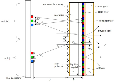
    We propose a new direct-lit color-matching LCD scheme to enhance the light energy efficiency by employing a specially designed lenticular lens array and RGB linear light sources, as shown in Fig. 1. Although many current LCDs larger than 40 inches employ the edge-lit backlight system, the trend is changing back to the direct-lit backlight system because of its higher image quality and lower cost. The light sources are placed as linear arrays of RGB light-emitting diodes (LEDs) at a distance
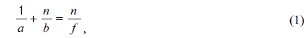
 a from the LLA. The LLA may be placed on the surface of the rear glass panel of thickness T1. The thickness of the liquid crystal layer is about 4 μm, so the distance b between the LLA and the CF is given by the sum of T1 and the LC thickness. The simple lens equation holds among the LLA, RGB LEDs, and the color filter as follows:

    image

    where f and n are the focal length of the lens element of the LLA and the refractive index of the LLA respectively. The direct-lit color-matching LCD is composed of several units including the RGB LED, LLA, and CF to form a large LCD system. The adjacent LLA units have a separation gap g between them, as shown in Fig. 1. From the optical arrangement of Fig. 1 that satisfies Eq. (1), it is possible that all RGB rays from the RGB LEDs entering the corresponding LLA unit fall onto the respective RGB color filter. The color-matching illumination can enhance the CF transmittance by as much as about 300% theoretically because the color-matched transmittance reaches about 90%, compared to the low transmittance of about 30% when white light is used, and so the energy efficiency of the LCD will be increased dramatically. However, there is some light loss due to rays from the LEDs falling outside the LLA of the corresponding unit. The separation gap between the adjacent LLA units is required to distribute equally the RGB light from the RGB LEDs into the RGB color filter subpixels. The required separation gap is

    image

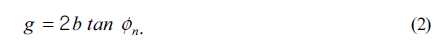
    The offset distance Δyn between the vertical positions of the nth LLA lens element and the nth CF subpixel is given by the following equation, due to refraction at the lens elements:

    image
    image

    where P is the pitch of the color filter subpixels along the vertical direction. The separation between the RGB LEDs should be adjusted according to the following equation, due to the dispersion among the red, green, and blue wavelengths:

    image

    where Δ s1 and Δ s2 are the separation distances between the green and blue LEDs and the green and red LEDs respectively.

    We performed a Monte Carlo optical simulation to check the performance of the direct-lit color-matching LCD system. The panel size was 120×100 mm2 and the parameters were a = 20 mm, b = 0.825 mm, and n = 1.5. The spacing between the red, green, and blue LEDs was 1.025 mm. The LEDs used were very small, 1.8×1×0.4 mm3, to make the spacing between adjacent LEDs as small as possible, as color nonuniformity becomes smaller with smaller LED spacing. The height and width of the LLA were 15.7 μm and 0.541 mm respectively, with 27 lens elements per unit. The separation gap between adjacent LLA units was 2.19 mm. The CF period was 0.5415 mm, a typical value for 50-inch LCDs. There were eight units for the prototype width of 120 mm. A diffuser sheet with a Gaussian scattering distribution of angular spread 20 degrees was assumed to be placed between the CF and front glass. The liquid crystal layer thickness of 4 μm was not included because it has little influence on the performance of the optical transmittance.

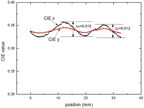
    The simulated results for the enhancement factors for luminance and illuminance were 195% and 146%, respectively. The view angles were 103.5 and 76.5 degrees along the horizontal and vertical directions respectively. The color nonuniformity was CIE Δx = 0.019 and CIE Δy = 0.01. The uniformities of the illuminance and spatial luminance were 92.5% and 82.9% respectively. The results of the simulation showed that the direct-lit color-matching LCD system has the potentialto increase the energy efficiency of an LCD while maintaining its optical characteristics.

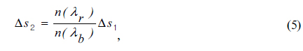
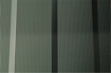
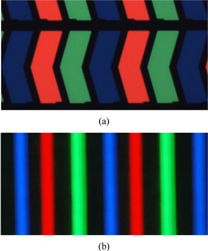
    A prototype direct-lit color-matching LCD system was constructed by fabricating and assembling the RGB LED linear arrays, the LLA sheet with 8 units, and the CF according to the simulation model. Figure 2 shows the RGB LED array module with RGB light beams emitted by the RGB LEDs. The peak wavelength and power for each of the RGB LEDs were 650 nm, 520 nm, and 470 nm and 3.6 lm, 9 lm, and 1.8 lm respectively. The separations between the adjacent red, green and blue LEDs were chosen to be 1.03 mm because the width of the CF subpixels was sufficient, compared to the width of the RGB color lines formed on the CF subpixels. Figure 3 shows a magnified portion of the fabricated LLA sheet. The height, radius and width of each lenticular lens were 15.7 μm, 1.7 μm, and 531 μm respectively, and the separation gap between the adjacent units of the LLA was 2.19 mm. The LLA sheet was made via the roll transfer process from a rolltype base moldmade using a photoresist thermal reflow procedure [10]. The top and bottom panels of Fig. 4 show the color filter used in the prototype; it had a period of 541.5 μm with a chevron pattern. The RGB color line images of the RGB LEDs are formed on the CF by the lenticular lens array in the same order as the CF RGB subpixels. The matching of colors between RGB CF subpixels and RGB color light beams contributes to the enhancement of the CF transmittance by as much as about 300% theoretically, compared to white-light transmittance. However, there exists the finite acceptance angle 2 θn (as shown in Fig. 1) that is limited by the finite width of the LLA units, and thus the effective enhancement of transmittance is much lower than the theoretical limit. Increasing the width of the LLA units would be helpful in enhancing the acceptance angle 2 θn, but a large angle may introduce more aberrations in the lenticular lenses, and thus color mismatch and nonuniformity would increase. Thus it is necessary to estimate the optimum condition for best performance of the color-matching LCD in terms of energy efficiency and color uniformity.

    III. RESULTS

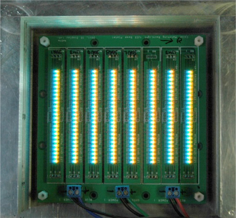
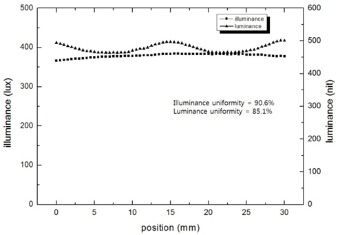
    The illuminance and luminance of the assembled prototype color-matching LCD were measured using the T-1 Luxmeter and the CA-210 colorimeter (Konica Minolta). Figure 5 shows the effect of transmittance change due to the CF position shift. The highest transmittance, designated as A in Fig. 5, is obtained when the color-matching condition is satisfied, and the transmittance becomes very low when the color-matching condition is not satisfied, designated as B in Fig. 5. The difference between the highest and lowest transmittance values is about a factor of 10, and the highest transmittance is about 2.4 times the average transmittance that is similar to that of a conventional LCD with uniform white-light backlighting. The slight mismatch between the color filter and the RGB lines is due to the unequal spacings between the RGB color lines that is introduced by the dispersion of the red, green, and blue wavelengths by the lenticular lens array. This effect is described by Eq. (5). However, since the mismatch is not serious, it is not corrected in our prototype experiment.

    The enhancements of luminance and illuminance were 192.5% and 139.1% compared to the non-color-matched LCD. These values are very close to the simulation results of 195% and 146% for luminance and illuminance respectively. The relatively low increase of the illuminance is due to the limited acceptance angle 2 θn = 40.16 degrees, because LED rays falling outside of this angle do not contribute to the transmittance enhancement from colormatching. The relatively large increase of the luminance, as much as 192.5%, comes from the narrowed viewing angle of 81 degrees due to the focusing effect of the lenticular lens array, compared to the conventional viewing angle of 110 degrees. Figure 6 shows the CIE color nonuniformity to be CIE Δx = 0.015 and CIE Δy = 0.012 centered at CIE(x, y) = (0.3255, 0.3386). The tolerance limit of the color nonuniformity of an LCD is typically 0.01, a value that human eyes cannot discriminate [11]. The CIE color nonuniformity comes mainly from the separation of RGB LEDs that induces mismatch among the RGB light fluxes. Reducing the separation between the RGB LEDs will lower the CIE color nonuniformity beneath the tolerance limit. In the prototype the minimum available separation was limited by the size of the LEDs currently available. Figure 7 shows the uniformity of the illuminance and luminance in terms of position along the x direction to be 90.6% and 85.1% respectively. The values of the illuminance are independent of the incident ray directions, so its uniformity is much better than that of the luminance, which is dependent on the directions of the incident rays.

    IV. DISCUSSION

    In the prototype the RGB color sources were constructed from linear arrays of small RGB LEDs. However, a better design for the RGB color sources would be RGB linear lightguides with RGB LEDs located at their ends. Because the human eye is more like a luminance sensor, uniformity in luminance is more important than in illuminance uniformity, and so it is necessary to improve the luminance uniformity in future research. The development of light sources consisting of RGB lightguides instead of LEDs will enable much better uniformity of the luminance and color uniformity with fewer blue LEDs.

    The color-matching LCD requires alignment of the RGB LED array, the LLA, and the color filter. The alignment of the RGB LED array with the LLA is less critical because any misalignment of the RGB LED array is reduced due to the demagnification effect of the LLA. However, the alignment of the LLA with the CF is important because otherwise Moire fringes and nonuniformity may occur. The alignment tolerance was not studied in this research because we focused on the feasibility of the color-matching LCD by fabricating a 4-inch sample. Alignment will become critical when the color-matching LCD is larger. A rough estimate of the alignment tolerance would be about 10 μm across a 1000 mm distance that corresponds to a 50-inch display. This alignment tolerance could be attained easily with the current alignment technology used in the LCD industry.

    V. CONCLUSION

    We demonstrated a prototype color-matching LCD comprised of a RGB LED array, an LLA with 8 units, and a color filter. Simulation and experimental results show that this color-matching LCD is a good candidate for an energy-saving LCD. The luminance and illuminance of the color filter were increased as much as 192.5% and 139.1% respectively compared to a non-color-matched LCD, due to the color-matching effect. The color-matching technique demonstrated in this prototype LCD will allow us to develop eco-friendly energy-saving displays in the near future.

참고문헌
  • 1. Nakasu E., Nishida Y., Maeda M., Kanazawa M., Mktani K., Hamasaki K., Nojiri Y. 2007 Technical development toward implementation of ultra high-definition TV system [SMPTE Mot. Imag. J.] Vol.116 P.279-286 google
  • 2. Yang X., Yan Y., Jin G. 2005 Polarized light-guide plate for liquid crystal display [Opt. Express] Vol.13 P.8349-8356 google
  • 3. Luo Z., Cheng Y.-W., Wu S.-T. 2014 Polarization-preserving light guide plate for a linearly polarized backlight [J. Display Technol.] Vol.10 P.208-214 google
  • 4. Chien K.-W., Shieh H.-P. 2004 Design and fabrication of an integrated polarized light guide for liquid-crystal-display illumination [Appl. Opt.] Vol.43 P.1830-1834 google
  • 5. Lee C.-H. 2012 Angularly positioned LED-based spatial temporal color separation system [Opt. Express] Vol.20 P.19109-19118 google
  • 6. Chen C.-H., Lin F.-C., Hsu Y.-T., Huang Y.-P., Shieh H.-P. D. 2009 A field sequential color LCD based on color fields arrangement for color breakup and flicker reduction [J. Display Technol.] Vol.5 P.34-39 google
  • 7. Huang Y.-P., Lin F.-C., Shieh H.-P. D. 2011 Eco-displays: The color LCD’s without color filters and polarizers [J. Display Technol.] Vol.7 P.630-632 google
  • 8. Lin F.-C., Huang Y.-P., Wei C.-M., Shieh H.-P. D. 2010 Color filter-less LCDs in achieving high contrast and low power consumption by stencil field-sequential-color method [J. Display Technol.] Vol.6 P.98-106 google
  • 9. Taira Y., Numata H., Nakano D., Sueoka K., Yamada F., Suzuki M., Noguchi M., Singh R., Colgan E. G. 2003 Color filterless liquid crystal display illuminated with LEDs [SID Symposium Digest of Technical Papers] Vol.34 P.1250-1253 google
  • 10. Park M.-K., Lee H. J., Park J.-S., Kim M., Bae J. M., Mahmud I., Kim H.-R. 2014 Design and fabrication of multi-focusing microlens array with different numerical apertures by using thermal reflow method [J. Opt. Soc. Korea] Vol.18 P.71-77 google
  • 11. Berns R. S. 2000 Principles of Color Technology, Ch. 4 Measuring Colors google
OAK XML 통계
이미지 / 테이블
  • [ ] 
  • [ FIG. 1. ]  A schematic of a direct-lit color-matching LCD that is composed of several units of optical structure, consisting of an RGB LED array, a lenticular lens array, and a color filter.
    A schematic of a direct-lit color-matching LCD that is composed of several units of optical structure, consisting of an RGB LED array, a lenticular lens array, and a color filter.
  • [ ] 
  • [ ] 
  • [ ] 
  • [ ] 
  • [ FIG. 2. ]  The RGB LED array module used as the RGB light sources.
    The RGB LED array module used as the RGB light sources.
  • [ FIG. 3. ]  Photo of the LLA sheet with separation gap of 2.19 mm between the adjacent units. Each unit has 27 lenticular lens elements.
    Photo of the LLA sheet with separation gap of 2.19 mm between the adjacent units. Each unit has 27 lenticular lens elements.
  • [ FIG. 4. ]  The RGB color beams (b) formed at the CF by the lenticular lens array and the RGB LED arrays. It is seen that each RGB color beam matches its RGB color filter subpixel (a).
    The RGB color beams (b) formed at the CF by the lenticular lens array and the RGB LED arrays. It is seen that each RGB color beam matches its RGB color filter subpixel (a).
  • [ FIG. 5. ]  The change of transmittance in terms of CF position shift. The transmittance for the best color-matching condition (a) is respectively 10.0 and 2.4 times as high as the mismatched transmittance (b) and the average transmittance that can be regarded as white-light transmittance.
    The change of transmittance in terms of CF position shift. The transmittance for the best color-matching condition (a) is respectively 10.0 and 2.4 times as high as the mismatched transmittance (b) and the average transmittance that can be regarded as white-light transmittance.
  • [ FIG. 6. ]  Profiles of CIE Δx and CIE Δy values in terms of the position along the x direction.
    Profiles of CIE Δx and CIE Δy values in terms of the position along the x direction.
  • [ FIG. 7. ]  Profiles of the illuminance and luminance in terms of the position along the x direction. The illuminance uniformity was 90.6 % and the luminance uniformity was 85.1%.
    Profiles of the illuminance and luminance in terms of the position along the x direction. The illuminance uniformity was 90.6 % and the luminance uniformity was 85.1%.
(우)06579 서울시 서초구 반포대로 201(반포동)
Tel. 02-537-6389 | Fax. 02-590-0571 | 문의 : oak2014@korea.kr
Copyright(c) National Library of Korea. All rights reserved.