Interchangeable lens products have been designed and developed for most film cameras [1]. However, single lens reflex (SLR) cameras have been digitalized recently. Thus, the manufacture and sale of SLR film cameras has nearly ceased. Digital single lens reflex (DSLR) cameras use a digital sensor instead of film. Since the first DSLR product did not have high pixel density, an interchangeable lens produced for film cameras could be used. However, recent DSLR products have high pixel density and so a new optical system must be developed [1]. Many companies have now launched new interchangeable lenses, dramatically increasing competition in this area. Various kinds of differentiation strategies are required to overcome the present market situation. While the typical way to differentiate products is through a superficial design change such as color, this approach is not influenced by engineering. From an engineering point of view, the specification of a product can be improved while increasing the cost and complexity of manufacturing. In this study, we suggest an optical calculation method in order to apply a distance window, which can achieve the appearance of product differentiation. In particular, we discuss a focusing lens cam calculation method in an interchangeable lens system.
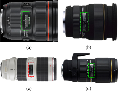
Prior to discussing the distance window specification, we review high-end luxury interchangeable lens trends and search for commonly applied differential factors. The most expensive lens is a fixed f-number lens that can achieve the same shutter speed from a wide to tele-position with an interchangeable lens system. Typical lenses correspond to 24-70 mm F/2.8 and 70-200 mm F/2.8 [2, 3]. Figure 1 shows 24-70 mm F/2.8 and 70-200 mm F/2.8 lenses. Several companies denote that these lenses are luxury products in the interchangeable lens segment [2, 3].
As shown in Fig. 1, the distance window is indicated by a dotted rectangular line. The distance window was a helpful function for adjusting focus in the past when the auto-focus (AF) function was not realized. This function notifies the position of an AF lens group so the user can recognize the AF lens position. This feature allows the user to easily achieve focus by eye [4]. However, the distance window has remained a feature even though the auto-focus system is now generalized. Nowadays, the distance window is designed as a luxury appearance factor as it is a preferred design feature for customers. Including the example given here, many companies adopt a distance window feature in the common luxury high-end interchangeable lens segment.
The distance window indicates the object distance that can be focused. Let us discuss narrow range to a single focus optical system, which does not change the field of view. A single focus optical system cannot change the field of view, so one only needs to change the position of the focus lens with object distance. For this reason, the focus lens group belongs only to the cam, and the object distance mark is printed outside of the cam. If we revolve the cam, the focus lens group shifts and the object distance mark also changes. For a zoom optical system that can change the field of view, if the cam is revolved, each lens group moves to a specific position to change the field of view according to the cam line. In this circumstance, it is impossible to move the focus lens group depending on object distance. Consequently, a distance window cannot be realized using only a simple printed cam in a zoom optical system, unlike that for a single focus optical system.
Generally, there is a zoom cam component for changing the field of view in a zoom optical lens system. Furthermore, the focusing cam must be used to focus according to object distance. We then assume the use of the combination of a focusing cam and a zoom cam to move the focusing lens group. However, the fact that the focusing lens group used to move distance, which depends on zoom position at the same object distance, makes the combination of the focusing and zooming cams impossible to apply [5]. However, both a focusing and zooming cam are still required. When the zooming cam is revolved, every lens group moves along with the focusing lens group. When the focusing cam is revolved, the focusing lens is moved for object distance and zooming movement in order to change the field of view. Furthermore, as the amount of focusing movement is different at each zoom position, the focusing lens group displacement must be different from the moving amount depending upon the focusing cam revolving angle. Thus, it is difficult to realize a distance window in a zoom lens system, unlike a single focus optical system.
A manual zoom is a zoom system manipulated by hand in an optical system. This kind of lens system can change the field of view faster than a motorized zooming lens system. This manual zoom can be used for highly skilled photography [6] such a zoom is shot with an adjusted detailed field of view.
In this study, we propose a new cam calculation method to realize a distance window in an interchangeable zoom optical system. In particular, we discuss a cam locus calculation method and analyze the error in the calculation.
II. OPTICAL DESIGN AND LOCUS CALCULATION
The distance window indicates the position of the focusing lens group at a specific object distance, as previously explained. Here, we treat the case that the zooming and focusing cams are coupled so, a focus ing cam must be compensated for a zooming cam.
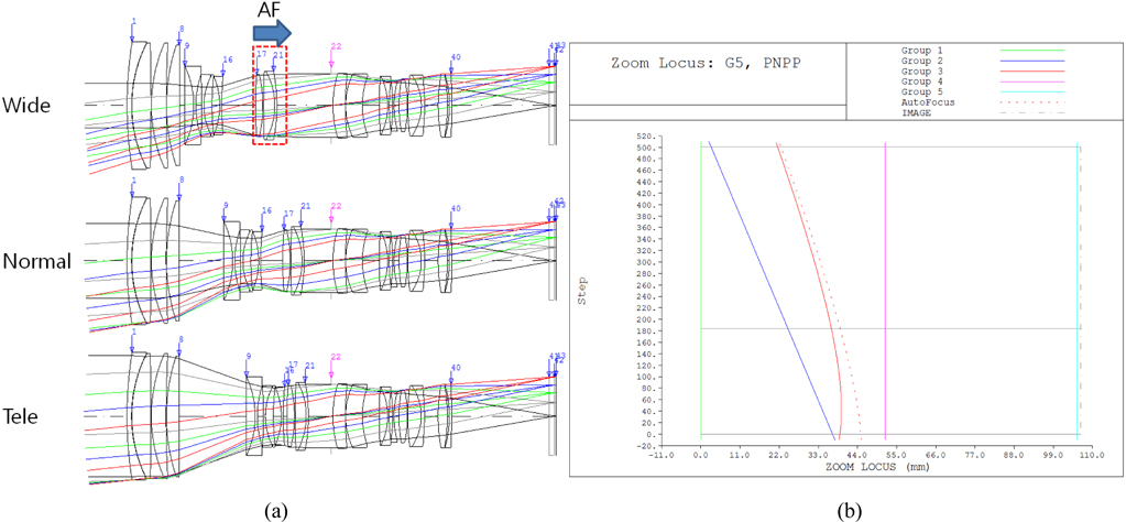
Figure 2 is the first example of JP2011-158599 [7] optical layout (Fig. 2(a)) and zoom locus (Fig. 2(b)). This optical system has a focusing lens group composed of 3 lens elements as shown in Fig. 2(a). The dotted lines in Fig. 2(b) indicate that the focusing locus is at an object distance of 2 m. In this example, there are different displacements according to object distance. For the first example of JP2011- 158599 [7], the diameter of the focusing lens group is smaller than the diameter of the focusing group of JP2011-099964 [8]. Thus, the structure of JP2011-158599 is possibly lighter and smaller, and has high auto-focusing speed. Therefore recent optical design and development trends focus on reducing the weight and size of the focusing lens group.
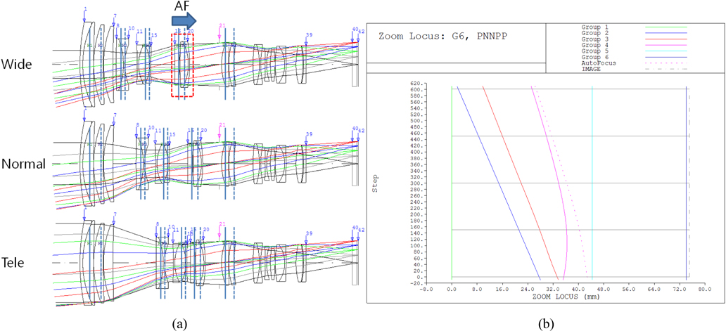
For the calculation of the cam locus to realize a distance window, we designed a new example optical system similar to the first example of JP2011-158599. The optical layout and zoom locus are shown in Fig. 3(a) and Fig. 3(b), respectively. In Fig. 3(a) for the optical layout, there are two lines which run perpendicular to the optical axis mean principal plane. The solid line is the first principal plane and the dotted line is the second principal plane. This optical system has five lens groups in total and a positive refractive powers the fourth lens group devoted to auto-focusing. The first and the fifth lens groups are fixed with respect to zooming. In Fig. 3(b), the dotted line is the focus locus at an object distance 1 m. This optical system has 31.5 degree field of view at a wide zoom position and 11.0 degree field of view at the tele-position. Furthermore, the f-number is fixed along with zooming, making this camera optical system compatible with a luxury high-end interchangeable product line.
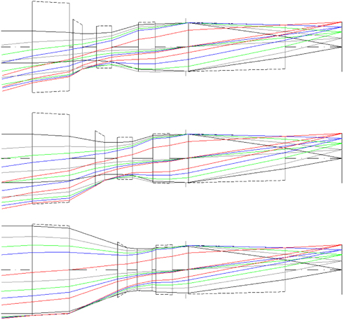
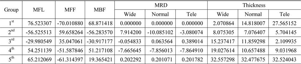
We need not know the entire optical system data. In order to realize a distance window, only the values for the locus calculation are required. Thus, each lens group can be transferred to a module lens group [9]. If transferring to a module lens, the optical layout will be the same as Fig. 4. Code V was used as an optical design software tool in this step. Figure 4 has three zoom positions: wide, middle, and tele. Optical system data can be input to the Code V software and transferred to a module lens. Every input parameter (1st, 2nd, 3rd, 4th, and 5th groups) to Code V is shown in Table 1. In Table 1, MFL is the effective focal length (EFL) of each lens group, MFF is the front working distance of each lens group, and MBF is the rear working distance of each lens group. MRD is the reduction ratio of each lens group, referring to the transverse magnification of each lens group. The value of addition from MFL to MFF is the distance from the first surface to the first principle plane in each lens group. The value of subtraction from MFL to MBF is the distance from the second principle plane to the last surface in each lens group. The effect of thickness in the module lens was not significant, but we input thickness data for each lens group in this paper.
[TABLE 1.] Module lens data for the example system used in this study

Module lens data for the example system used in this study
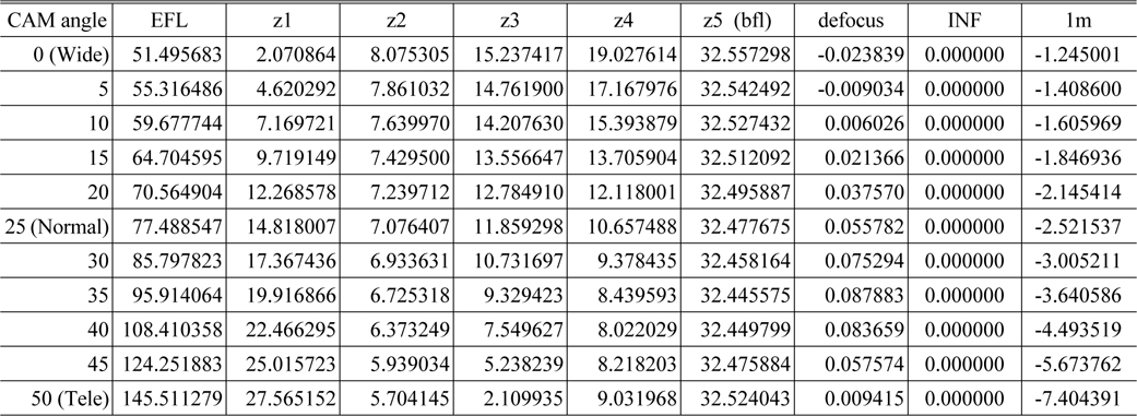
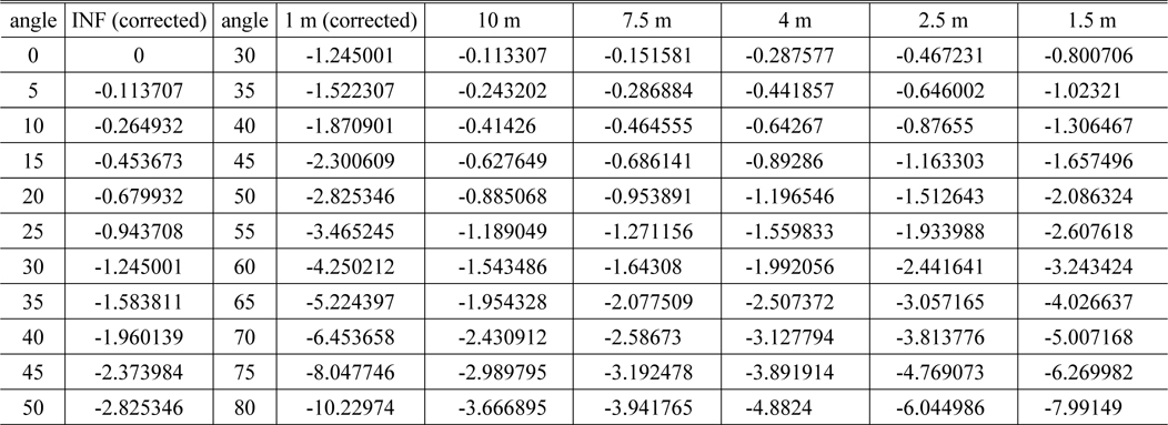
[TABLE 2.] Zoom locus and EFL of the example system for various cam angles

Zoom locus and EFL of the example system for various cam angles
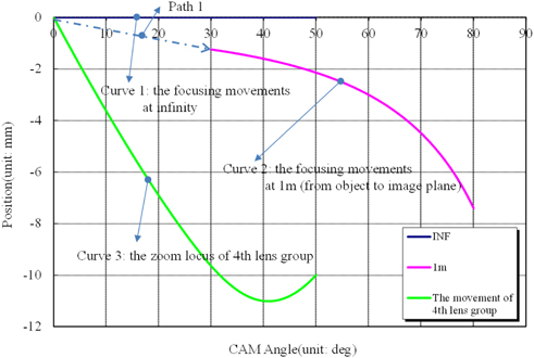
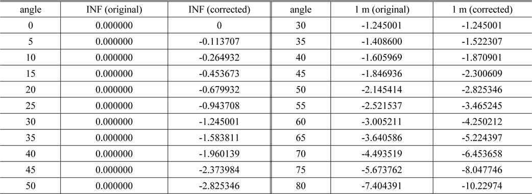
Using the data in Table 1, the zoom locus can be calculated. Table 2 shows the results of the zoom locus calculation. The method of zoom locus calculation is explained in Reference 11. A graph of the data in Table 2 is in Fig. 3(b). In the table, ‘zi (i = 1, 2, 3, 4)’ is the spatial distance between the ith lens group and the i+1th lens group. The symbol “z5” is the spatial distance from the image plane to the 5th lens group, referring to the back focal length (BFL). “INF” denotes the position of the focusing lens group (4th lens group) at infinite object distance. Furthermore, ‘1 m’ refers to the position of the focusing lens group (4th lens group) at an object distance of 1 m. The (-) sign is chosen so that the focusing lens group shifts in the image plane direction. ‘Defocus’ is the best focus position in the final optical design. Generally, spherical aberration cannot be perfectly corrected; therefore, ‘defocus’ is the best position of the focusing lens group to maximize the MTF value at a specific spatial frequency. In the zoom ring revolution, we have to consider zoom ring angle in order not to make an improper revolution due to the inflection point of the locus. As shown in Fig. 3, the 2nd and 3rd lens groups simply move directly, but the 4th lens group has an inflection turning point, so the zoom ring angle must be accounted for. In the case of an optical system such as that shown in Fig. 3, we assume that the zoom ring angle is 50 degrees, meaning that the total revolution angle is 50 degrees from the wide position (the widest field of view) to the tele-position (the most narrow field of view).
In contrast to the zoom ring revolution angle, we also require the focus ring revolution angle due to the mechanical problem of the focusing lens group. Here, we assume that the focus ring revolution is 30 degrees in the example optical system. When the focus ring revolution angle is 0 degrees, the focusing lens group displacement is 0 mm and the object distance is infinite. When the focus ring revolution angle is 30 degrees, the focusing lens group displacement will shift and the object distance is minimum.
III. THE CORRECTED CAM CONCEPT AND CALCULATION METHOD
Here, we assume that the lens condition can be changed from the wide zoom position at infinite object distance to the tele zoom position at the minimum object distance. If we revolve the focus ring the first 30 degrees with zoom ring fixation, the focus lens group will move to the image plane for 1.245 mm. If the zoom ring revolves by 50 degrees, the focusing lens group will move more to the image plane by 6.195 mm so that the total distance of the shift will be 7.404 mm from the initial position. Thus, the focusing cam revolving angle of the focusing lens group will be 80 degrees total. Using Table 2, the focusing lens group locus is the same as that in Fig. 5. If we revolve the zoom ring by 50 degrees after revolution of the focus ring by 30 degrees, the locus will follow path 1 and curve 2 of Fig. 5. On the other hand, revolution of a zoom ring may occur before the revolution of the focus ring. If zoom ring revolves without focus ring revolution, the focus lens group will pass 30 degrees of the focusing cam and stop at 50 degrees of the zoom cam. As the position of the focusing lens group is 1.245 mm from the image plane at 30 degrees of the focusing cam, 20 degrees of additional revolution involves the final motion of the focusing lens group by 2.145 mm from the image plane. However, the correction amount for the zoom cam will be 0 mm → 1.245 mm → 2.142 mm. In this study, the zooming cam of the focusing lens group is called the corrected cam. Consequently, the locus of path 1 in Fig. 5 affects not only the zooming cam but also the locus of the focusing lens group, which approaches curve 2. The locus of the focusing lens group also affects the focusing cam in order to define the corrected cam.
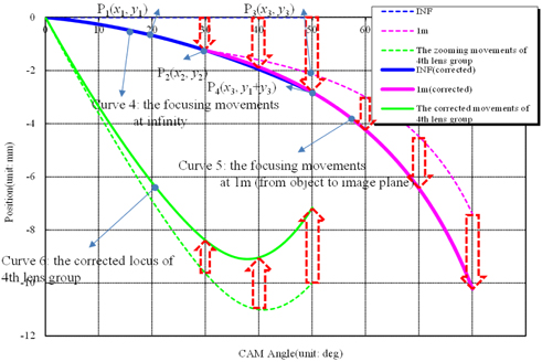
Figure 6 has a final focusing cam and a corrected cam. The focusing lens group passes through curves 4 and 5 in the revolution of the zoom and focus ring, which is the locus data of the focusing cam. In addition, the corresponding value for the range 0-50 degrees for the focusing cam and zoom locus value of the 4th lens group are the data used for the corrected cam. We now consider how to calculate curve 4 and curve 5. When revolving the focusing ring, the positioning point of the focusing lens group is P2 in Fig. 6. However, when revolving the zoom ring by 50 degrees, the positioning point of the focusing lens group would be P3. However, the positioning point of the focusing lens group moves to P4 in Fig. 6 because we need to consider the shift in the focusing lens group for curve 4. This value is a summation of curve 4, which is the focusing lens group correction value at infinite object distance and the locus of the focusing lens group at the minimum object distance. Therefore, when revolving the zoom ring by 50 degrees, the focusing lens group must be at P4, rather than P3, because the difference in P1 values between the focus and zoom ring is added. In this way, the following curve is formed when curve 4 is a 2nd order curve from the origin (0,0) through P2 and P4:
In these equations,
To calculate equation (2), refer to Table 2 in Fig. 3 and Fig. 4 example optical systems. Using Table 2, each variable of equation (2) can be calculated as:
[TABLE 3.] The corrected cam data
The corrected cam data
In Table 3, INF(corrected) is the value of curve 4 in Fig. 6, 1m(original) is the displacement of the focusing lens group at the minimum object distance. Furthermore, 1m (corrected) is the sum of 1 m (original) and INF (corrected), corresponding to curve 5 in Fig. 6. However, since the focus ring is revolved for 30 degrees and the zoom ring revolves at the minimum object distance, 1 m (corrected) must start from 30 degrees rather than 0 degrees. Furthermore, since INF (corrected) should be corrected about the locus of the focusing lens group, INF(corrected) is also needed to sum curve 3 in Fig. 5. These summation values are shown on curve 6 in Fig. 6. Since the two curves must be connected at points P2 and P4 in the corrected cam, which is the connection between curve 4 and curve 5, the cam design could be a problem for no differential. Thus, we must calculate a continuous and differential curve using curve fitting or interpolation. In this study, we found the final data shown in Table 3 using curve fitting polynomials.
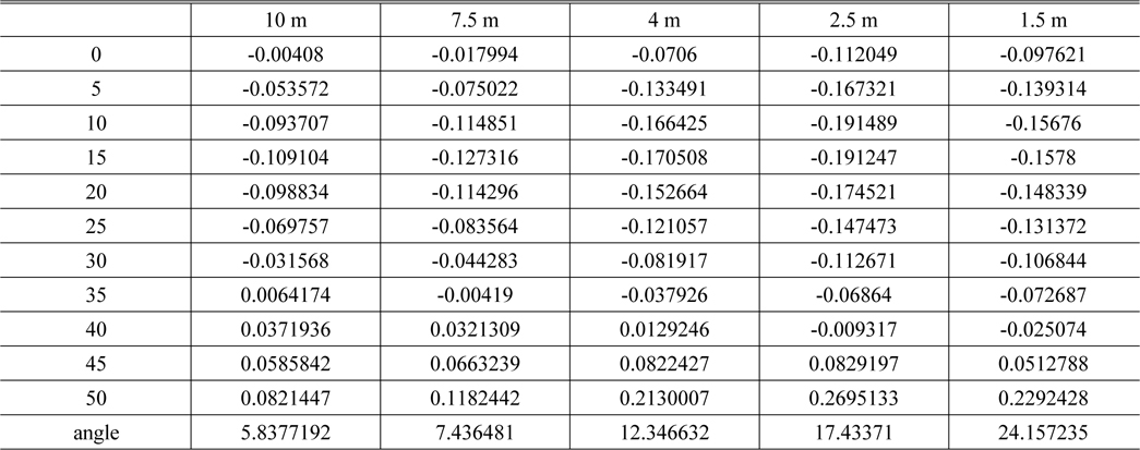
Figure 7 shows a curve fit of a 6th order polynomial shown in Table 3. The original curve and the fit curve are the same. Table 4 shows the error between the original cam data and the curve fit. As shown in Table 4, the maximum error is about 0.02 mm, which means that the fitting error is not a problem in comparison to other manufacturing errors such as Newton’s ring and thickness errors. In order to obtain a more precise cam curve, spline interpolation may be used [10]. All data for the corrected cam have been obtained for realizing a distance window. However, the design of the structure depends on a mechanical engineer using all the data of the corrected cam.
[TABLE 4.] Parameters extracted from the curve fitting of cam data
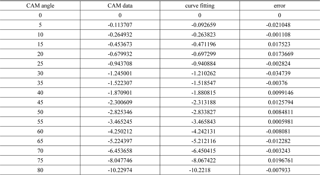
Parameters extracted from the curve fitting of cam data
IV. ERROR ANALYSIS OF CAM DATA
We found corrected cam data in Section 3. This data is accurate only at infinite and minimum object distance. However, we have not checked the accuracy at another object distance. Table 5 shows calculations for focusing lens group displacement. These values are a summation of the original focusing lens group displacement and the corrected values. For example, the focusing lens group displacement is the value of ‘INF (corrected)’ subtracted from a 2.5 m object distance (from image plane to object) in Table 5.
[TABLE 5.] The movements of the AF lens group for other object distances

The movements of the AF lens group for other object distances
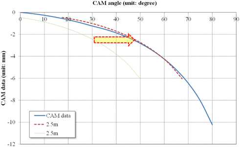
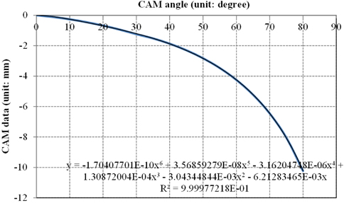
Figure 8 shows corrected cam data at an object distance of 2.5 m. In Fig. 8, ‘cam data’ is calculated as in Table 4. As previously explained, the cam angle is 30 degrees, which is the maximum angle of the focus ring at the minimum object distance. We need to calculate the starting point of the angle except at the minimum object distance. This value can enable the distance window to be printed. Since ‘cam data’ in Fig. 8 is calculated in the same way as the polynomials in Fig. 7:
In equation (3),
In Equation (4), the values of
[TABLE 6.] The error of various object distances and the starting angle

The error of various object distances and the starting angle
In Table 6, the maximum error is tele (50) at an object distance of 2.5 m. The focusing lens group shifts by about 0.270 mm along the image plane with the cam curve in Fig. 8. Therefore, the focus ring must be revolved to a low angle in order to achieve more precise focus. In order to get a more precise value, we have to calculate a polynomial equation such as Equation (3). If we calculate the value in this way, the error of the angle is less than 1.2 degrees, indicating that the error in the focus ring angle is 1.2 degrees at an object distance of 2.5 m for a total revolution angle of 30 degrees. This error cannot be eliminated. Although the calculation method for the corrected cam has an error, this error is not critical because the customer cannot recognize such an error. In addition, the auto-focusing function aids in adjusting precise focus, so there are no further problems.
Several companies are producing interchangeable DSLR or CSC lenses. In this kind of product, there are various kinds of lens differentiation factors, and certain specifications are preferable to customers, such as the distance window. In particular, mechanical manual zoom and manual focus are commonly supported specifications. However, the AF group is linked to the zoom cam and moves. Because the AF group moves with object distance, one cannot realize a distance window with only a zoom locus calculation. In this study, we proposed an optical calculation method to realize a distance window for product differentiation. Examples of optical systems were shown. Using an example optical system, we suggested a corrected cam to realize a zoom and focus ring in one cam. Furthermore, we showed a cam calculation method using a 6th order equation and curve fitting and applied this calculation to an example optical system. We also analyzed the error in the corrected cam calculation at a middle range of object distance. The error was not critical to use because the customer will not be able to recognize such an error. In the future, we plan to propose and analyze a more precise and improved cam calculation method.