The auto-berthing of a ship requires excellent control for safe accomplishment. Crabbing, which is the pure sway motion of a ship without surge velocity, can be used for this purpose. Crabbing is induced by a peculiar operation procedure known as the push-pull mode. When a ship is in the push-pull mode, an interacting force is induced by complex turbulent flow around the ship generated by the propellers and side thrusters. In this paper, three degrees of freedom equations of the motions of crabbing are derived. The equations are used to apply the adaptive backstepping control method to the auto-berthing controller of a cruise ship. The controller is capable of handling the system non-linearity and uncertainty of the berthing process. A control allocation algorithm for a ship equipped with two propellers and two side thrusters is also developed, the performance of which is validated by simulation of auto-berthing.
Berthing is the process of positioning and mooring a ship beside a quay, jetty, or floating dock, usually for the purpose of loading or unloading. For large ships such as a container or a cruise ship, berthing is done with the aid of tug boats. When the ship approaches the berthing position, forward tug boats are used to hold the bow to prevent the ship from contacting the quay. Aft tug boats are then used to push the ship towards the quay. If the lateral speed of the ship is higher than the desired speed, the tug boats would be used to retard it. By careful operation of the propellers and rudder, the ship is positioned a few meters away from the quay, and thereafter brought nearer by means of tug boats and mooring ropes. The entire operation is actually very complex and time consuming.
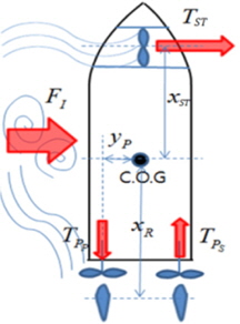
Crabbing is the pure sway motion of a ship without surge velocity, and is induced by a peculiar operation method known as the push-pull mode. The push-pull mode is induced by the combined manipulation of the main propeller and side thrusters. The two propellers are made to generate the same amount of thrust while rotating in opposite directions, thereby exerting a yawing moment on the vessel without inducing longitudinal motion. By the simultaneous operation of the side thrusters, the push-pull mode is implemented, resulting in the generation a large lateral force. When a ship is in the push-pull mode, an interaction force is induced by complex turbulent flow around the ship generated by the propellers and side thrusters. Crabbing is a slow sway motion and can thus be applied to berthing if the ship is equipped with propellers and the thrusters are close to the berthing position. Some requirements for effective crabbing and berthing were presented by Quadvlieg (1998), namely the maintenance of a lateral speed of 0.25(
There have been some recent studies on crabbing. Lee et al. (2000) simulated crabbing of a ship with twin rudders and twin skegs. However, whereas crabbing involves low-speed maneuvering and pure lateral motion, their mathematical model was a conventional model used for simulating longitudinal maneuvers. According to Yoshimura (1988), the forces acting on a ship are generated by the cross flow drag-which is proportional to the square of the lateral speed-and not by the lift in low speed manoeuver. Experiments on the hydrodynamic forces of a ferry in crabbing motion involving pure sway and pure yaw without longitudinal velocity were conducted by Yoo et al. (2006). Based on experimental investigation, Quadvlieg and Toxopeus (1998) proposed simple techniques for calculating the interaction force, but the techniques were shown to be inadequate for estimating crabbing capability. Studies of auto-berthing are mainly based on the optimal control theory, the neural network theory, or an expert system (Yamato et al., 1993; Hasegawa and Kitera, 1993; Im and Hasegawa, 2001). A system for planning the optimal berthing path of a ship was developed by Djouani and Hamam (1995). Yamato et al. (1993) and Hasegawa (1994) proposed auto-berthing controllers based on the neural network theory for considering the nonlinear characteristic of low-speed ship maneuvering. Im and Hasegawa (2001) proposed a parallel hidden layer neural network controller for improving auto-berthing performance beyond that achieved by a conventional neural controller. They, however, focused on berthing with the aid of a rudder, which is not realistic for extremely low-speed maneuvering, wherein the rudder is incapable of generating sufficient lateral force and yaw moment. There has hardly been any study that took into consideration the interaction force and severe environmental disturbances such as strong winds. Moreover, there have been few studies on auto-berthing by crabbing.
An auto-berthing controller should be able to handle the uncertainty in modeling the interaction force, as well as the nonlinearity of the force acting on the hull during crabbing. Adaptive control is a control method that adapts to a system with uncertainty, whereas backstepping control was developed by Kokotovic (1992) for designing the controller of nonlinear dynamic systems. Adaptive backstepping control is a combination of the two methods and is used for systems characterized by nonlinearity and uncertainty, such as those used for crabbing.
In this paper, we develop a mathematical model of crabbing for enhanced berthing simulation. The interaction force and wind force are incorporated in the model, and are assumed to be unknown disturbances during the design of an adaptive backstepping controller that can adapt to unknown disturbances. The Lyapunov stability theory is employed in the design of the controller, which is verified by simulations of crabbing, berthing, and unberthing under wind conditions. The paper is finally concluded by drawing some conclusions.
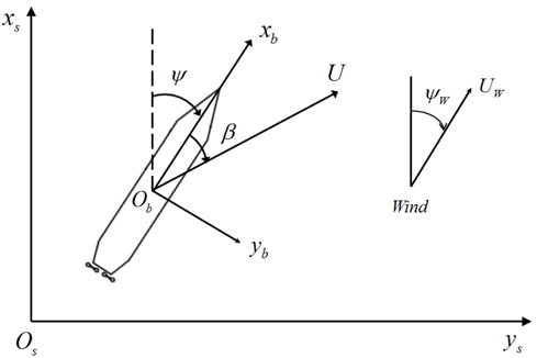
The coordinate system used in this study is shown in Fig. 1. It consists of the body-fixed coordinate

where
The design of the auto-berthing controller must be preceded by the mathematical modeling of the ship motion. The three degrees of freedom equations of the surge, sway, and yaw can be expressed as follows:

The terms on the right-hand side of Eq. (2) represent the external forces acting on the ship. In this study, the following modular type mathematical model is used to express the external forces:

The modular type mathematical model is expressed in terms of the force acting on the hull, the propeller force, the rudder force, the side thruster force, the interaction force, and the wind force. The rudder is excluded from the control algorithm because it is incapable of generating sufficient force and moment when the longitudinal speed of the ship is almost zero. Here, the subscript
The hull force consists of the added mass term, hydrodynamic damping term, and restoring term. The added mass is the pressure-induced force due to the motion of the ship, and it is proportional to the acceleration. The restoring term is the hydrostatic force due to the weight and buoyancy of the ship, and does not have a horizontal component. The added mass is determined by the empirical formula of Motora (1959). The hydrodynamic damping is produced by the wave, drag, and vortex shedding effect. During the crabbing motion for berthing, the surge velocity is nearly zero and the sway velocity is increased by the side thrusters and propellers in the push-pull mode. The sway velocity is also very small, which makes the wave-making damping effect negligible. The inclusion of these terms in a mathematical model for predicting the lateral force affords greater accuracy than the conventional model. A static sway test, dynamic sway test, static yaw test, and dynamic yaw test without forward speed were conducted by Yoo (2006) and the results were used to develop a mathematical model of the force acting on the hull during crabbing. The equations of the model are as follows:

The thrust of the propeller is a function of its thrust coefficient, rotational speed, and diameter. The sign function is adopted to consider the direction of the thrust of the propeller:

where

where
The side thruster is used when the rudder is incapable of generating sufficient lateral force and yaw moment at low speeds. In the push-pull mode, the propellers produce a large yaw moment, and the side thruster is therefore used to compensate for the yaw moment. The thrust of the thruster is a function of its thrust coefficient, rotational speed, and diameter. The direction of the thrust of the side thruster during berthing is different from that during unberthing; hence, a sign function is adopted:

where

where
In the push-pull mode, the fluid particles accelerated by the reverse rotation of the propeller impact the stern of the ship, whereas those accelerated by the side thruster change the flow field on the lateral side of the ship. Quadvlieg (2011) conducted a push-pull mode model test and observed a difference between the measured force and the sum of the forces of the propeller and the side thruster. The difference is defined as the interaction force, which is expressed as follows:

According to Eq. (9), the interaction force is a function of the thrust of the reverse propeller and the force generated by the side thrusters. The direction of the interaction force is the same as the crabbing direction.
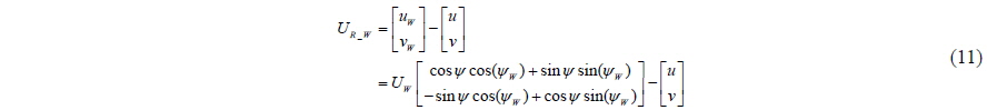
The wind force is considered as an environmental disturbance. The wind force is considered in the berthing problem because it has been suggested that the requirements for effective berthing are dependent on the wind conditions Quadvlieg (1998). The equations of the wind force can be obtained as expressed by Eq. (10).
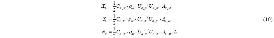
where

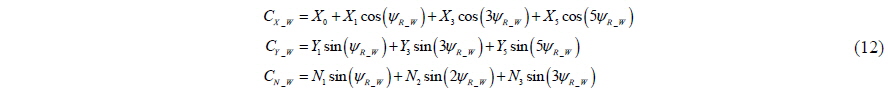
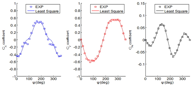
The wind coefficients

where

The coefficients
A backstepping controller can deal with the system nonlinearity of the berthing maneuver. An adaptive controller can also be used to compensate for the unknown disturbance. Based on the work of Fossen (1994), an adaptive backstepping controller for the vector system is designed in this section.
>
Adaptive backstepping controller
Three degrees of freedom nonlinear equations of the planar motion can be expressed as

where

The space-fixed velocity vector and acceleration are given by


Using Eqs. (16) and (17), Eq. (14) can be expressed as

The matrices can be defined as

Eq. (18) can thus be reformulated as

The first backstepping variable is defined as the error between the position vector and reference model position vector for the ship to track:

The virtual control is defined as

where

Λ is the positive definite matrix. The


A Lyapunov candidate function is

where

The time differential of the Lyapunov candidate function is given by

By substituting Eq. (25) into Eq. (28), we obtain

The control law is chosen as follows:


The adaptive law is defined as

The time differential of the Lyapunov candidate function can thus be made negative semi-definite as follows:

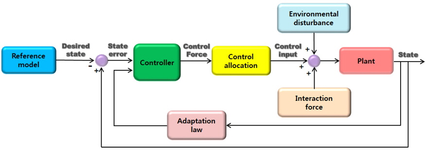
By LaSalle’s theorem, the backstepping variables 1 z and 2 z approach zero as the time tends to infinity. Fig. 5 is a block diagram of the adaptive backstepping control.
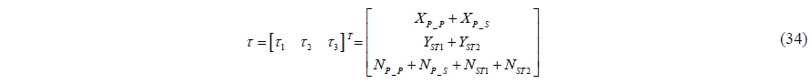
The determined control force vector is allocated to the propellers and side thrusters. The rudder is incapable of generating sufficient lateral force and yaw moment during crabbing and is therefore excluded from the control allocation. The relationship between the control force vector and the thruster forces can be expressed as follows:

where the subscripts

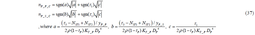
Based on Eqs. (8), (9), and (35), the command for the rotational speed of the side thrusters can be expressed as

The propellers are used to compensate for the yaw moment generated by the side thrusters and balance the longitudinal force. Based on Eqs. (5), (6), and (34), the command for the rotational speed of the propellers can be expressed as
In this paper, it is assumed that the dynamics of the propellers and side thrusters are in accordance with first order actuator dynamics, and that the time constant

A reference model is used to prevent wastage of control effort as a result of excessive position error in the initial phase. In this study, a second order dynamic system is established for use in referencing the model dynamics. The reference model dynamics can thus be written as

A cruise ship equipped with twin propellers and two side thrusters is used for the simulation. The principal dimensions of the ship are given in Table 1.
[Table 1] Principal dimensions of cruise ship.
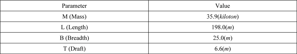
Principal dimensions of cruise ship.
The control gain matrices are diagonal and their components are given in Table 2. The values of control gain matrices are chosen by trial and error in order to obtain the satisfactory berthing performance.
[Table 2] Components of control gain matrices.
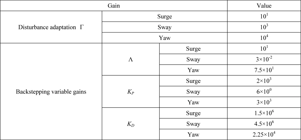
Components of control gain matrices.
Three scenarios were simulated, namely crabbing in wind, auto-berthing in wind, and auto-unberthing in wind. The establishment of the wind condition is based on the study of Quadvlieg (1998). It is assumed that the behavior of wind velocity and direction can be specified as a normal distribution function.
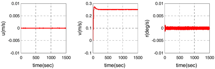
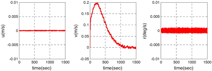
The simulation of crabbing in wind is used to check whether the cruise ship satisfies performance criteria 1 given by Hooren (1985), namely that a lateral speed of 0.25
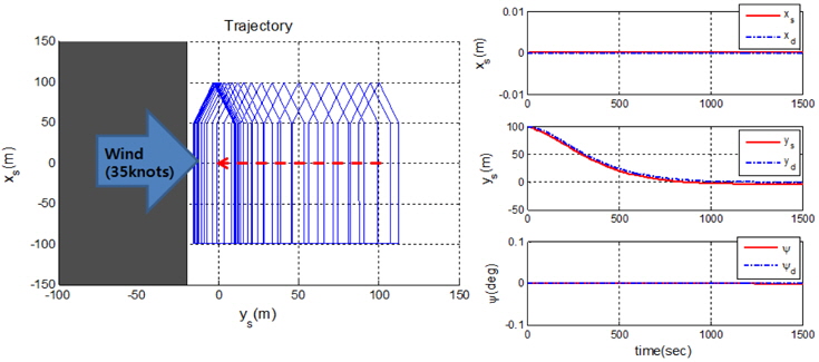
It can be observed from Fig. 5 that the ship trajectories are in good agreement with the reference model position vector. Fig. 6 shows the velocity vector of the ship. The lateral velocity is 0.25
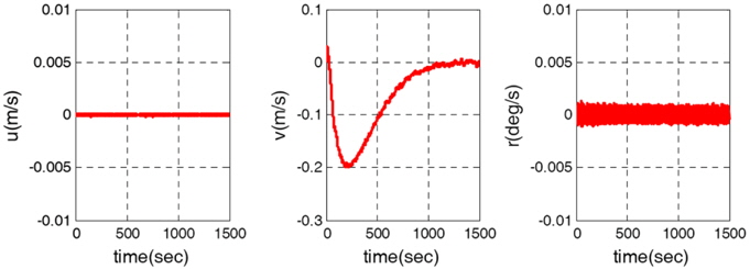
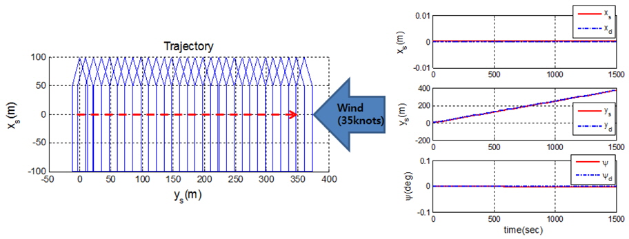
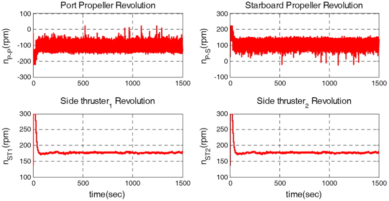
The simulation of auto-berthing in wind is used to verify whether the ship satisfies performance criterion 2, namely the ability to berth and unberth under a wind speed corresponding to Beaufort 7 without the aid of tug boats. The initial position vector of the ship is [0
Although a wind force acts on the ship, the simulation results indicate stable berthing. Moreover, the heading angle error and the longitudinal error is almost zero. The maximum lateral velocity is about −0.2
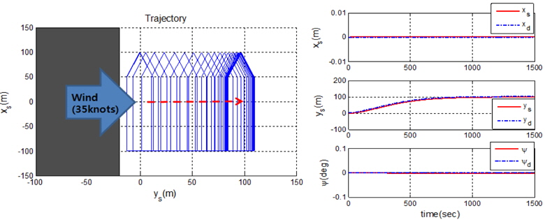
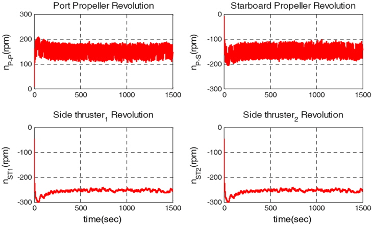
The simulation of auto-unberthing is used to verify the control allocation algorithm. If the control allocation is not designed properly, inappropriate results may be obtained depending on the direction of the lateral motion. The wind condition is the same as that of scenario 2. The initial position vector and initial reference model position vector are both [0
It can be seen from Fig. 11 that the designed control algorithm produced stable unberthing. The rotational speed of the side thrusters is negative and the lateral wind force is positive, which indicates that the rotational direction of the side thrusters must be negative to compensate for the wind force as the ship approaches the reference model position.
The equations of the crabbing maneuver of a ship were derived in this paper. The hull force, propeller force, side thruster force, interaction force, and wind force were considered as external forces acting on the ship. Because crabbing is an extremely low speed maneuver, the rudder was excluded from the control algorithm. Errors may be present in the model of the interaction force and the wind force of actual berthing. The interaction and wind forces were thus defined as uncertainty terms in the design of the controller. The terms were estimated by the adaptive law and compensated for by a control input. The other terms were controlled by the backstepping control method. The results of auto-berthing simulations that were performed to verify the derived control law confirmed the effectiveness of the designed controller.