Offshore LNG production and natural gas supply using FLNG concept are promising due to its capability to solve increasing challenges faced in onshore project by local demographic constraints and increasing environmental and safety regulations. Floating LNG can be classified into LNG FSRU which is used as LNG regasification/receiving facility, and LNG-FPSO which is used for LNG production/export facility. LNG FSRU is intended as an alternative for the area where onshore infrastructure is not well established and/or environmental restrictions are very strict to construct onshore receiving facility. Further LNG FPSO provides some attractive benefits by developing the gas at location of the gas field, and it doesn’t require subsea pipeline and additional upstream facilities. LNG FPSO concept will put vitality into approximately 2,400 marginal gas fields which were delayed because of excessive investment cost in the world. LNG FSRU also provides commercially competitive and effective solutions to the areas mentioned earlier.
In this paper, some of the key FLNG technologies will be introduced: some design challenges and their solutions and a couple of design innovations devised for LNG containment systems. At the same time, some examples of how to overcome those challenges encountered during the development of the FLNG will be introduced in the following sections.
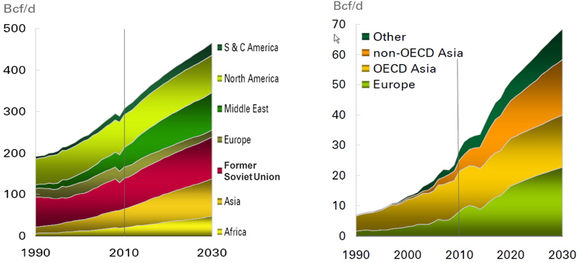
Increase of population in developing countries and rising income levels are one of key drivers of energy demand. Further shift of population to cities will drive increase of additional energy demand because the population residing in cities consumes more energy compared to rural areas. According to BP Energy Outlook 2030 published in 2011, gas production and demand will be increased substantially, which is shown in Fig. 1.
With this trend of greater demand for energy and with major focus on cleaner energy, natural gas will play a major role in energy supply chain. Further improvement and innovations in technology will drive the development of offshore LNG production and natural gas supply .
To successfully execute FLNG project and stay ahead of challenges faced, it is important to improve existing technology as well as develop new technologies.
FOUNDATION TECHNOLOGIES FOR FLOATING LNG
Existing natural gas supply chain is comprised of production from offshore platform, subsea pipeline and onshore LNG process plant including LNG export terminal, LNG carrier, and LNG regas plant including receiving terminal. This conventional gas supply chain gives certain level of reliability while requires large scale investment for various areas with long-term development period.
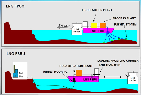
Based on the expertise on the shipbuilding and offshore plant accumulated by Shipbuilding Companies, e.g. FPSO and FSRU, it is possible to move LNG production facilities and natural gas supply from onshore to offshore; in case of LNG FPSO, pre-treatment module, liquefaction module and power plant on topside and cargo containment system and offloading facility on floating hull.
In case of LNG FSRU, typically, regas plant can be integrated into hull design as part of shipboard equipment together with power plant and cargo containment system and offloading facility on floating hull for small and medium scale capacity.
Subsea pipeline to onshore LNG process plant in the case of LNG FPSO and onshore receiving facility in the case of LNG FSRU are not required anymore, and thus the integrated LNG facility will provide one-stop solution to combine and simplify the LNG process plant, which has better safety performance with floating type storage and offloading facility.
Concept of FLNG is shown in Fig. 2.
Offshore liquefaction and regasification are relatively new concepts which have not yet been commonly implemented. It is already recognized to be potentially more dangerous than the oil FPSO. The key facilities which have a significant impact on the safety are the topside liquefaction process, the LNG offloading system, the LNG storage facilities and its associated facilities.
Each of these facilities has to be carefully studied from operational, economical, and especially safety point of view.
It is very important for the FLNG to have reliable operational capability with the given weather environments in the target field. Therefore mooring system has to be carefully selected to provide enough capability with least operational limits considering water depth, expected lifetime and environmental conditions.
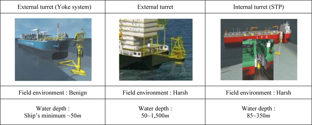
[Table 1] Turret mooring system.

Turret mooring system.
It is well known that turret mooring system provides excellent solutions for a wide range of applications as shown in Table 1. Considerations for field environment condition including water depth and maintainability (i.e. bearing replacement) will be important technical selection criteria for turret mooring system.
The proven mooring system allows FLNG to freely weathervane 360 degrees, enabling continuous operations in moderate to harsh weather conditions since turret arrangement can allow FLNG to adopt the direction of the least resistance against waves, wind and currents. The turret mooring system is generally arranged in the forward part of the hull structure for this purpose.
A turret mooring system is composed of a fixed turret column supported by an internal or external structure via a bearing arrangement for free weathervaning around the turret. Also the turret mooring system should be designed to ensure safe working of the underwater fluid transfer or riser system from seafloor to turret. Different design layouts can be considered for the turret concepts, for example a number of catenary or semi taut mooring lines fixed to the seabed are used.
It is one of the key functions for FLNG to store produced LNG on a floating structure, those LNG containment technologies available for LNG carriers can be applied to FLNG as well. However additional consideration has to be paid for the implementation of selected technology, since lifetime operation should be allowed on specific site even in harsh weather condition.
[Table 2] Typical types of LNG cargo containment system.
Typical types of LNG cargo containment system.
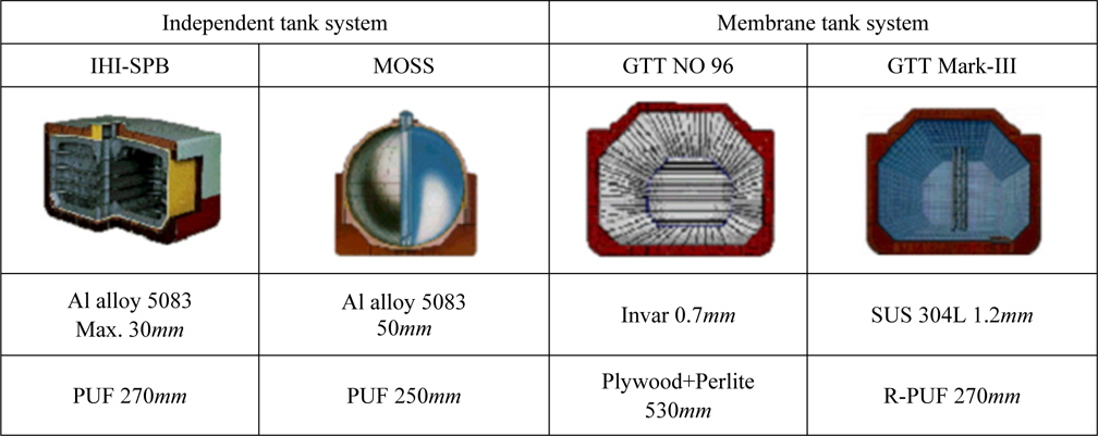
Since the first LNG marine transportation in U.S.A. in 1952, LNG Cargo Containment System (hereinafter, CCS) has been developed into various types in accordance with the development of materials and manufacturing technologies; (i) membrane-type system and independent-type system. Although the reputation of the membrane -type systems was slightly affected by the sloshing issues, the membrane-type LNG CCS has played a major role in LNG marine transportation because of the commercial advantages in manufacturing, storage efficiency and operational reliability (Ogawa, 1984).
Mainly, 4 types of containment systems are being utilized for the LNG CCS as shown in Table 2.
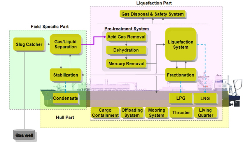
For optimal arrangement for topsides and hull, it is important to understand the configuration of overall module arrangement and their functions of each system of topside LNG facilities. And most appropriate liquefaction technology should be selected in consideration of safety, functionality and other optimization factors. Brief process system configuration is presented in Fig. 3 for FLNG and Table 4 for FSRU respectively.
Process technology for LNG FPSO can be presented as follows:
In general, Feed gas is received from the gas rich well reservoir and passes through gas/liquid separation system where it will separate gas from liquid components. Separated gas will be pre-treated to remove acid gas, such as CO2 and H2S, if it is required. Gas leaving the acid gas removal system will pass through dehydration system which will dry the gas to prevent ice formation in the downstream liquefaction unit. Gas from the dehydration system will get into the mercury removal unit which will remove any traces of mercury to prevent downstream cryogenic unit from damage.
After mercury removal, gas will pass through the liquefaction system, where it will be cooled below its boiling point, as natural gas is converted to Liquefied Natural Gas to be stored in LNG storage tanks in the Hull. FLNG process facility, as similar to oil FPSO, has process supporting systems like a cooling medium, heating medium, flare, MEG (Mono Ethylene Glycol), fuel gas and chemical systems to support LNG process. Air, Nitrogen, Water and steam system are also required as a general utility system for the purpose of proper plant operation. Main part of FLNG hull consists of LNG, LPG, condensate oil containment, offloading system, mooring system, thrusters and living quarters.
The liquefaction is the key element of the LNG plant and it is the major cost component of the LNG plant. It is essential to choose a proper technology based on careful consideration and project requirements. The liquefaction technology selection should be based on various criteria considering thermal efficiency, power consumption, CAPEX (Capital expenditures), OPEX (Operating expenditures), etc. Table 3 shows the various kinds of liquefaction technologies available in the market.
[Table 3] Liquefaction technologies (Eckhardt, 2010).
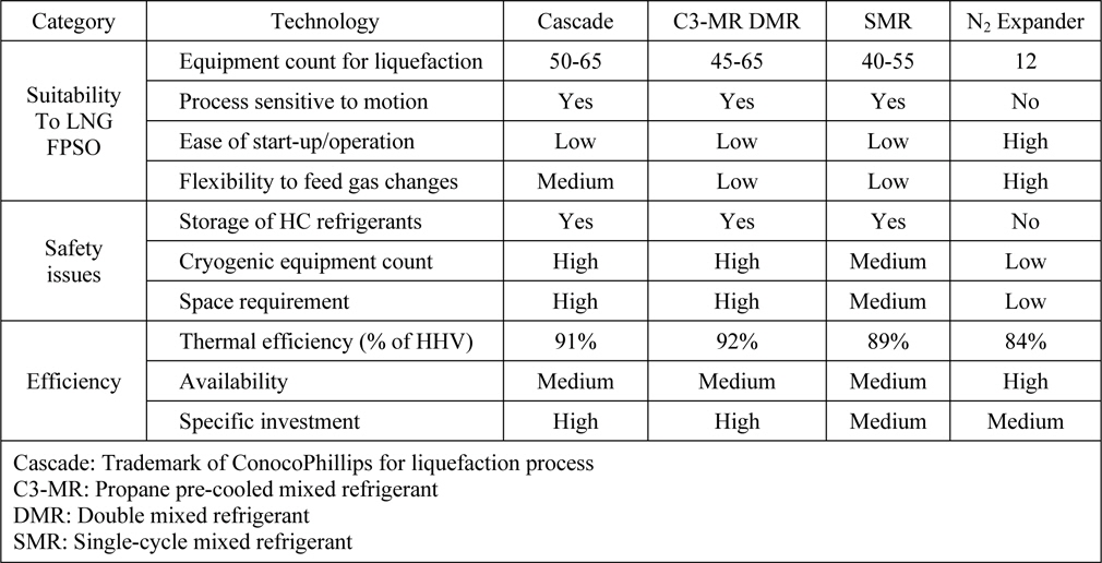
Liquefaction technologies (Eckhardt, 2010).
Process technology for LNG FSRU can be presented as follows:
LNG is transferred into cargo tank by dedicated LNG feed pump, from cargo tanks, LNG will be sent to high pressure booster pump which is used to make high pressure before entering LNG vaporizer, after that LNG will be vaporized and sent to end user. If required by end user, odorant can be mixed after vaporization process.
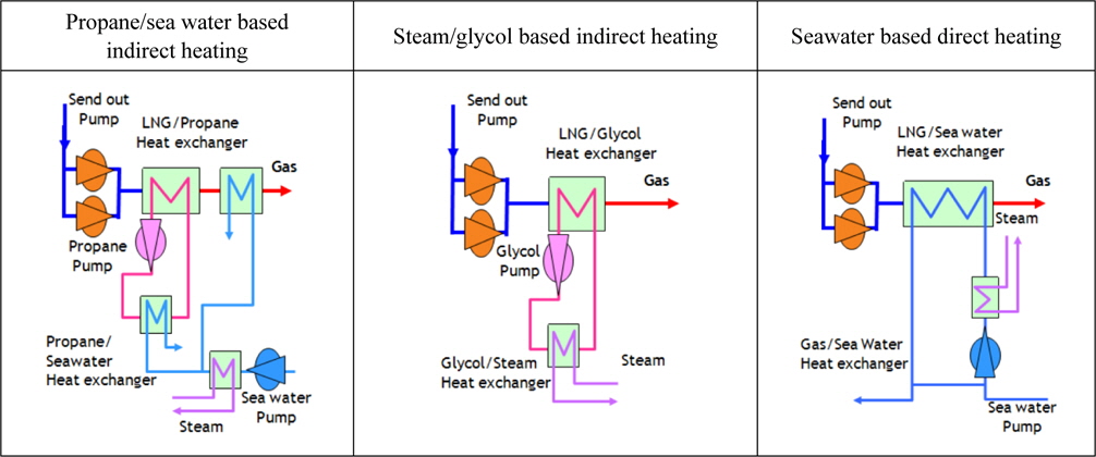
Type of LNG vaporizer which is used for gasification process is selected carefully in consideration of environmental conditions. For example, the area where sea water is appropriate as heating medium is recommended to apply vaporizer using sea water. However, the area where sea water temperature is too low to be heating medium, or not allowed in environmental point of view, other types of heating medium such as propane, glycol, etc should be considered. In addition, of environmental aspect of heating medium discharge, process can be classified into “OPEN LOOP” and “CLOSED LOOP”. Heating medium in “CLOSED LOOP” is circulated without discharge to overboard after regas process. Typical technologies such as propane/sea water based indirect heating, steam/glycol based indirect heating, and seawater based direct heating are presented as shown on Table 4. Other important criteria such as efficiency, required electric consumption, CAPEX, OPEX, etc are also considered at system planning stage. Further development in these technologies will increase feasibility of FLNG project and create a way forward for successful development of cleaner energy for future.

Regas technologies.
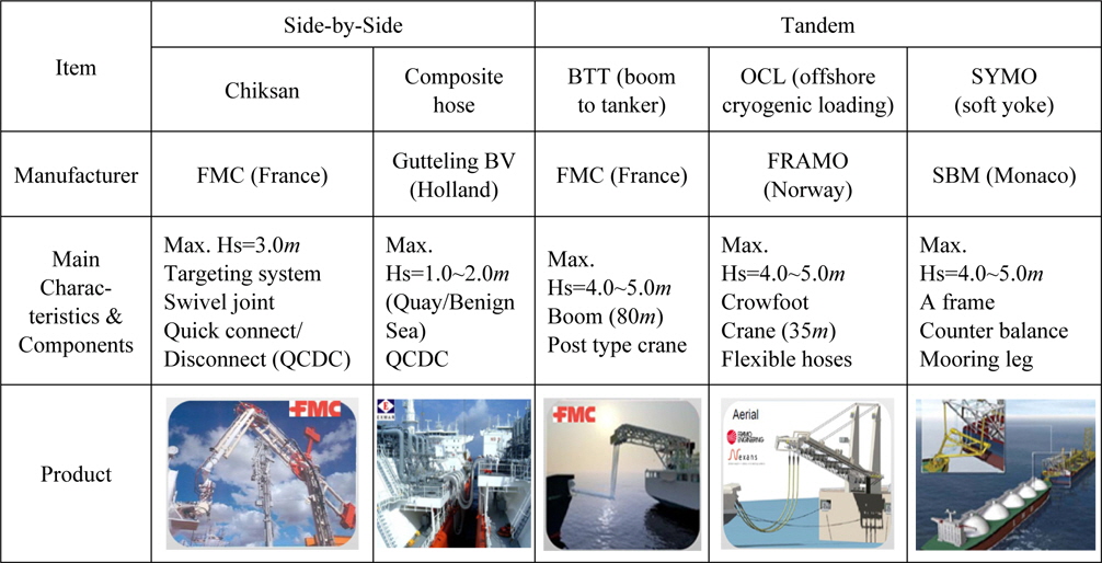
LNG transfer from FLNG to LNG carrier is also key element in FLNG design and various type of transfer systems have been developed in different configuration such as side-by-side and tandem offloading (MacDonlad et al., 2004).
Side-by-side offloading uses Loading Arm facility for offloading operation to a ship alongside FLNG. Since two floating vessels are very close during offloading operation, it is important to control relative motions between the two vessels with state-of-the-art position monitoring systems to monitor both the position and the velocity of the LNG carrier.
Tandem offloading system allows a FLNG-to-LNG carrier transfer of LNG in a tandem configuration. By utilizing Dynamic Positioning system on the LNG carrier and heading control on the FLNG the LNG transfer operation can be carried out even in harsh weather conditions. Hydrodynamic analysis tools are used for a set of environmental load cases to verify feasibility. Tandem offloading allows offloading to LNG carrier in more rough sea conditions and offloading operation is permitted for significant wave height up to 4-5
[Table 5] LNG offloading technologies.

LNG offloading technologies.
Despite of vast improvements in technology and availability of analysis software, a number of challenges still remain for the design of the largest FLNG. In order to solve and mitigate those challenges, the essential FLNG requirements need to be understood and proper solutions to be found out.
>
Determination and design of CCS
There are several design requirements for FLNG which need to be incorporated in the initial and concept design stage. A few of essential design condition and technology development to overcome design challenges are presented as below.
One of the major constraints is limited space. Different from the onshore facility, the design of floating facility will be affected by the dimension of hull structure, which may restrict the seamless integration of topsides and hull equipment. In case of LNG FPSO, large scale topsides module requires sufficient deck area for topsides facility maintaining the safety standards and flexibility to LNG production.
Secondly, large scale topsides module leads to heavy topsides weight. To successfully manage such increase in weight, a robust hull structure arrangement is required. At the same time, large capacity of LNG volume needs to be considered.
In the case of FLNG, in addition to the foregoing requirements, cargo sloshing due to the liquid flow is one of the important considerations for the stiffness of containment system. Containment system described in Table 1, a variety of project requirements and sea conditions of operation area should be investigated. Independent tank structure such as MOSS and SPB has no sloshing issue because the influence from the liquid motion (sloshing) inside these tanks is already taken into account in its design. However, those have drawbacks such as CAPEX in SPB and Topside layout issues in Moss. Membrane type in contrast to SPB has advantage in CAPEX, but technical constraints in sloshing. Once a facility is in operation, wave motion will bring another major challenge. LNG CCS should be robust enough to resist against sloshing impact when partially filled in different operation conditions.
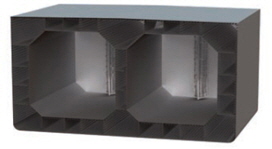
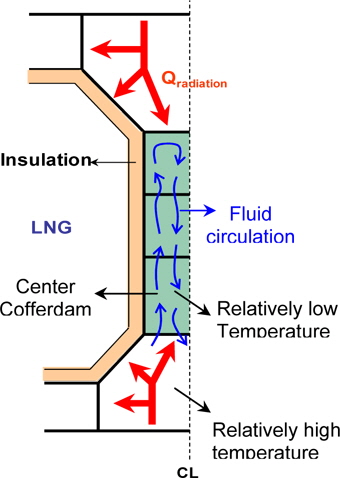
To meet the minimum requirements as stated above, two (2) Rows LNG CCS configuration has been recommended as shown in Fig. 4. These two parallel arrangements of cargo tanks including center cofferdam along the longitudinal direction are applied to the design.
One of the major challenges faced was the design of the center cofferdam, as no reference code was available for design of two (2) rows LNG CCS configuration. IGC code, which is generally applied for the design of LNC carrier and regarded as the most relevant design guideline, states that “Longitudinal structural steel should be designed without any heating at the designated temperature criteria.”
Calculations based on IGC code show the most severe temperature on structural steel may reach up to -65○
Although the 9% Nickel or Duplex stainless steel can provide the more low temperature resistance characteristics, they are not practical structural material for fabrication of center cofferdam when considering the huge size of FLNG facility, which may lead much more time and effort to complete the fabrication. Because low temperature carbon steel has been normally applied for the construction of the LNG carrier, the usage of low temperature steel is recommended to avoid any possible problem and will be more practical for fabrication.
Since there is no design guideline for two (2) row LNG CCS configuration, new design criteria have to be settled based on the fit to purpose concept considering actual site environmental conditions where the FLNG facility will be located. It has to be verified by computerized techniques.
Research was carried out based on new design criteria for FLNG (Consultation with Classification Society). As per new design criteria, actual site conditions is considered against conventional requirement of seawater temperature as 0○
Heat transfer was calculated for radiation effect due to temperature difference between hull plates as per Eq. (1):

where σ is Stefan-Boltzmann constant, ε is emissivity, F is view factor, A is surface area, and T is Kelvin temperature.
Further, heat transfer calculation was done by providing non-tight stringer and circulating fluid into center cofferdam. Based on the new design criteria, results obtained are summarized as presented in Table 6.
[Table 6] Design criteria and results.
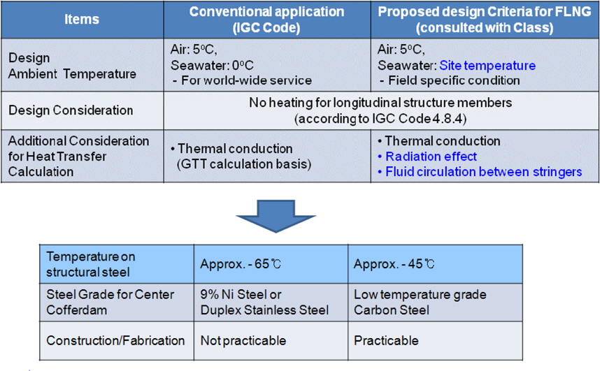
Design criteria and results.
Final result based on new design criteria shows the lowest temperature on structural steel is higher than -45○
It is necessary to establish the standard guideline with relevant authority which can be utilized for FLNG facility development based on the current experience.
>
Safety design-cryogenic spill, fire risk, and passive fire protection (PFP)
FLNG design needs to maintain the utmost level of safety as it needs to deal with the effects of winds, waves and currents in the open sea. Few critical aspects from safety design point of view are briefly described as below.
Cryogenic Spill - Once spilled it can create a considerable volume of gas which can further expand once in contact with air to form even larger volume of gas which can result in asphyxiation. Further, due to very low temperature it can lead to material failure. In case of spillage, proper consideration needs to be given for containment of spillage and proper ventilation need to be provided.
Fire Risk - Cryogenic liquids are also associated with fire hazards. Spillage of flammable liquid like liquid hydrogen can greatly increase the risk of fire. Even in case of inert gases like nitrogen, spillage can lead to escape of nitrogen, leaving oxygen enriched condensate that can increase the flammability of material. Equipment containing cryogenic liquids should be kept away from combustible material to reduce the risk of fire.
Explosion Risk - Cryogenic liquids have high expansion ratios and vapor leakage can lead to over-pressure. During spillage it expands very quickly and if proper venting is not available it may lead to over-pressurization of the area or create oxygen condensate thereby leading to explosion risk.
These are only few of the major aspect that needs to be considered for safe and reliable design. For successful development of FLNG project, design criteria and mitigation action should be established beforehand and agreed upon. It will help the identification of various safety studies required for hazard identification. Once design criteria are finalized and mitigation plans are prepared, they should be incorporated in the final design and development of FLNG. This is required to maintain the safety and integrity of the system in different operation scenarios.
PFP is the counter concept of AFP (Active Fire Protection) on fire proofing system. AFP means the devices which directly extinguish a fire such as sprinkler, deluge, mist system, fire detection and drain system. While, PFP makes a target object maintain its functionality and structural integrity during a certain period without any extinguishment effect. Generally, cementation materials, fibers, composites and epoxy coatings have been used as PFP. The epoxy coatings have been used most widely on offshore because of cost, constructability and corrosion. CHARTEK of International Paintings and PITT-CHAR of Sigma Coatings are particularly well-known.
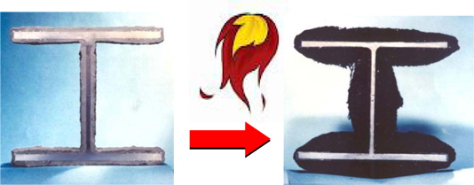
For the topsides of the FLNG facility, fire case scenarios have been identified from hydrocarbon source and release frequency analysis. The identified fire scenarios are gas jet fire, liquid jet fire, flashing liquid jet fire and pool fire. Those fires can give effect on both of the topsides and the substructure. The hydrocarbon fire can reach 1,200○
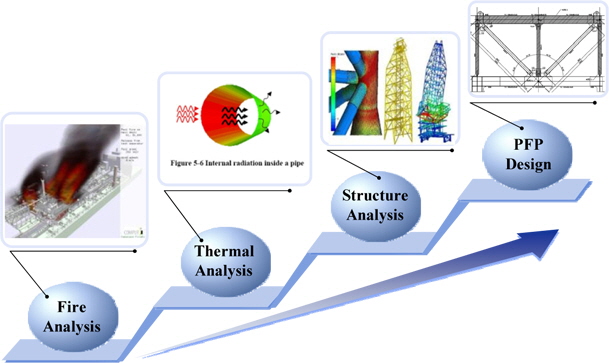
The PFP design is divided into three steps roughly. The first is fire load analysis. The heat flux and impact duration are analyzed for the accidental fire in the exposed region. The resulting temperature of each structure is calculated using the consequential data from the fire load analysis at the second step of thermal analysis. The last step is nonlinear structural response analysis to estimate the structural behavior due to the performance reduction of material as per temperature increase. The PFP design is carried out according to the process, as presented in Fig. 7.
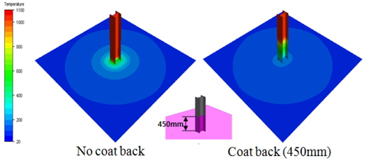
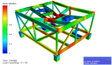
Those design method has been used for estimating stability of topsides structure, integrity of vessel and piping containing hydrocarbon with depressurized system and coat back application. The nonlinear structural response analysis verifies the security of global stability of structure. If it is not secured, the recalculation has to be carried out considering application of PFP for the failed members, as illustrated in Fig. 8. Through these iterative works, the most optimized design of PFP can be recommended. The optimized design of PFP is useful to CAPEX, maintenance of corrosion and inspection of welding for customer and to remove useless installation of PFP for construction yard.
Furthermore, FLNG has a cryogenic hazard due to unintended leak of the inventory of LNG accompanied with high temperature from a fire hazard. Similar design scheme can be performed to assess the structural security like PFP design. The epoxy coating of protecting structure from cryogenic hazard is so called CSP (Cold Spill Protection) as shown in Fig. 9. CSP is to keep the temperature of structure exposed to cryogenic spill within acceptable limits during a certain period like PFP for a fire.
Sloshing in LNG storage tank caused by vessel motion produces additional forces that might affect the system integrity. In order to provide increased reliability on LNG CCS, enhanced technologies and alternatives have been developed. This kind of continuous development for the LNG containment system related technologies will contribute to sustainable FLNG design in the future. As typical examples of research works for new technologies related to LNG containment system, combined cargo containment system and ABAS (Anti-BOG Anti Sloshing) Blanket System are presented in this paper.
Under the consideration that SPB tank has drawback in terms of CAPEX even though it shows very good performance for sloshing aspect, combined containment system (hereinafter Combi LNG) was developed (Kim and Lee, 2011). It is an object of this development to provide a Floating LNG having an LNG loading and unloading system in which membrane tank and SPB tank are arranged in combination and in which a liquefied natural gas is loaded and unloaded through the SPB tank so as to minimize the influence of sloshing.
SPB tank which has superior capability to sloshing aspect will take care of LNG loading and unloading while LNG in SPB tank is transferred to other membrane tank. CAPEX increase will be minimized providing similar level of sloshing behaviors by this application. In addition, the fore end or aft end arrangement of robust SPB tank will provide additional safety in relation with various collision scenarios (Kim and Lee, 2008).
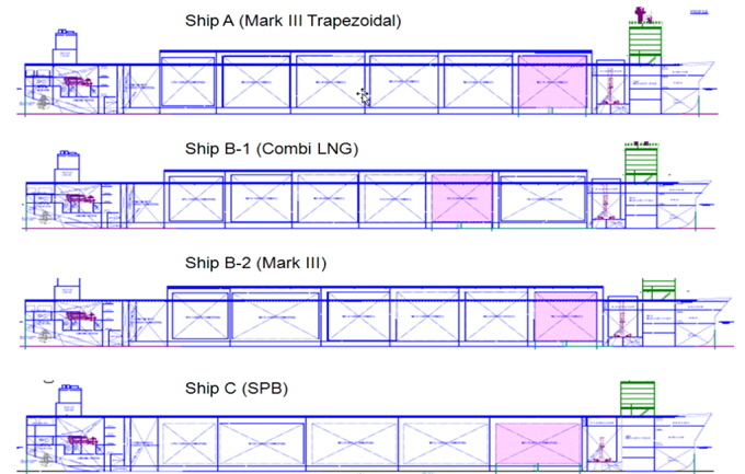
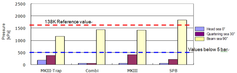
For the validation of Combi LNG’s design principle, various cargo tank combinations as shown in Table 7 & Fig. 10 were investigated through sloshing model tests based on 170,000
[Table 7] Tank configurations for model test.
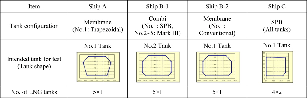
Tank configurations for model test.
The aim of the model test was to evaluate the level of sloshing induced impact loads on the most exposed tank locations for four different 170,000
The result shows that the overall sloshing behaviors of Combi LNG (Ship B-1) and SPB (Ship C) are much better than that of Mark III containment system (Ship A and Ship B-2) at Head sea and Quartering sea as shown in Fig. 11. High pressure observed at Beam Sea is not an issue because thrusters will be operated for free weathervaning around the turret. In addition, the fact that relatively high pressure observed for SPB (Ship C) was assumed as resonance effect between upper chamber structure and natural frequency of FLNG.
Another object of Combi LNG arrangement is to provide an Floating LNG having an LNG loading and unloading system in which a membrane tank and a SPB tank are interconnected by a separate connection pipeline so that a liquefied natural gas can be moved between the membrane tank and the SPB tank through the connection pipeline when the liquefied natural gas is loaded to or unloaded through the SPB tank, thereby avoiding a filling limit which would otherwise be a cause of sloshing.
In case of LNG FPSO, it includes at least one SPB tank and at least one membrane tank, both of which are arranged in combination. The numbejavascript:;r of the SPB tank and the membrane tank may vary with the size of the LNG FPSO.
Because of superior capability of SPB tank against sloshing impact, SPB tank is arranged in the fore part and/or after part of the LNG FPSO where the sloshing is severely generated by a harsh weather conditions.
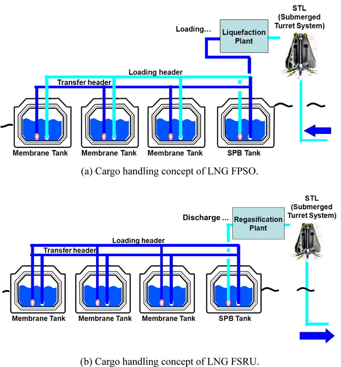
The membrane tank is positioned continuously from SPB tank in case where SPB tank is arranged in one of the fore part and/or after part. In other words, the membrane tank is installed in a position other than the fore part and/or after part to avoid the influence of sloshing and to eliminate the risk of safety accident. The LNG FPSO in which the membrane tank and SPB tank are arranged in combination includes a submerged turret loading (STL) system provided in the fore part thereof for stably introducing the natural gas produced in a gas field. LNG FPSO further includes a liquefaction plant by which the natural gas introduced through STL is liquefied into a cryogenic liquid. The liquefaction plant is connected to SPB tank via a pipeline. The SPB tank and the membrane tank are connected by transfer header pipeline. The liquefied natural gas filled in the SPB tank is distributed to the membrane tank via transfer header pipeline.
In case of LNG FSRU, the unloading system of the LNG FSRU is designed to regasify the liquefied natural gas in a floating state on the sea and to supply the regasified natural gas to the land facilities through seabed pipelines.
The pump in SPB tank is connected to a regasification plant of the LNG FSRU through a pipeline. The regasification plant is designed to heat up and regasify the cryogenic liquefied natural gas. The natural gas regasified in the regasification plant is unloaded to the land by means of a STL system provided in the fore part of the LNG FSRU for stabilizing the process of feeding the natural gas through seabed pipelines. The SPB tank and the membrane tank are connected by transfer header pipeline.
Description will now be made on cargo handling principle of Combi design for the LNG FPSO and FSRU respectively.
First, a process of loading the natural gas performed in the LNG FPSO will be described with reference to Fig. 12(a). The natural gas produced in a marine gas field is stably introduced into LNG FPSO by means of the submerged turret loading plant and is transformed into a cryogenic liquefied natural gas while passing through the liquefaction plant. The liquefied natural gas is first sent to the SPB tank via loading header pipeline. If the liquefied natural gas is filled up to a certain level in the SPB tank, it is distributed to the membrane tanks through the transfer header pipeline by means of the pump. Even if the SPB tank is arranged in the position where severe sloshing occurs, the sloshing may affect the membrane tank. The membrane tank may be quite vulnerable to the sloshing during the time when the liquefied natural gas is filled in 10 to 70% of the membrane tank. In view of this, it is preferred that the liquefied natural gas is suitably distributed through the transfer header pipeline depending on wave conditions on the sea. Further, it is preferred that the liquefied natural gas is distributed in such a manner as to reduce the time period during which 10 to 70% of the membrane tank is filled with the liquefied natural gas.
Next, a process of unloading the natural gas performed in the LNG FSRU will be described with reference to Fig. 12(b). The liquefied natural gas filled in the SPB installed in the fore part or after part of the LNG FPSO is discharged through the pipeline by means of the pump. Simultaneously, the liquefied natural gas stored in membrane tanks is fed to the SPB tank through the transfer header pipeline by means of the pumps provided in the membrane tank. This means that the liquefied natural gas stored in membrane tanks is discharged via the SPB tank at all times. Further, movement of the liquefied natural gas between the membrane tanks helps minimize the sloshing which would occur when 10 to 70% of the membrane tank is filled with the liquefied natural gas. The liquefied natural gas discharged through the pipeline is regasified by the regasification plant and then unloaded to the land through the seabed pipelines by means of the submerged turret loading system. The liquefied natural gas is loaded and unloaded through the SPB tank that has an increased resistance against the sloshing. This makes it possible to overcome the sloshing.
>
ABAS (Anti-BOG anti sloshing) blanket system
As mentioned above, the sloshing motion phenomenon has been one of technical challenges to be solved in the LNG CCS in the marine transportation. In order to solve the sloshing problem, independent type of LNG CCS such as MOSS type and SPB was designed. MOSS type, spherical independent tank system, was engaged in the Japan-Indonesia trade. In the other hand, SPB type which is one of the other independent systems adopted the design concept of baffle plates (Dodge, 2000) such as complicated swash bulkheads and stringers to reduce the sloshing motion inside the tanks.
But those damping appendage structure concepts cannot be applied into the membrane-type LNG CCS which uses the hull structure as the load bearing tank body and have the relatively soft insulation material between the LNG cargo and the hull structure (Roni et al., 1978).
Even though the baffle plates could be introduced into the membrane-type system to reduce the sloshing motion inside the LNG tanks, it would be unavoidable to install them onto the hull structure for load bearing and this will inevitably leads to heat paths and deteriorates the insulation performance of the LNG CCS. Therefore, the sloshing issues in the membrane-type LNG CCS are partially treated by adopting the octagonal shape to reduce the impact load due to sloshing motion and reinforcing the insulating structures of LNG CCS.
In spite of these design changes, the sloshing concern related to possible damages on the CCS is still limiting the operating conditions and so the new business chances; LNG tankers are allowed to operate with the LNG cargo filled more than 70% or less than 10% of the tank height.
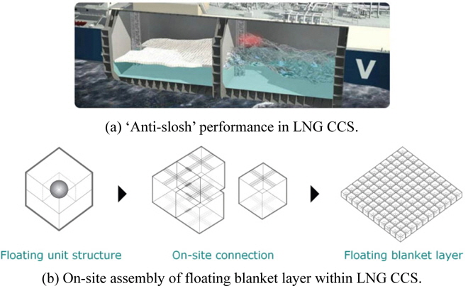
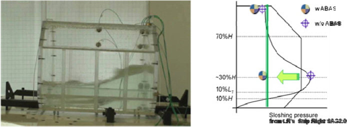
Recently, a new device which uses flexible membrane structures to restrain the fluid motion on the free surface is being studied (Anai et al., 2010). An innovative solution named as ABAS (Anti Boil-off gas Anti Slosh) blanket system, as presented in Fig. 13 (Chun et al., 2011a) can dampen the motion of LNG inside the LNG cargo vessels in operation in a cheap and effective way and, as a result, the sloshing loads on CCS can be reduced significantly.
Various sloshing model tests were carried out for the validation of design principle and technical benefits (i.e. dramatic reduction of sloshing motion) as illustrated in Fig. 14 (Kim et al., 2011).
The production of prototypes of floating unit structures which are assembled into a floating blanket layer, ABAS blanket system, shows the applicability in real LNG vessels. During the manufacturing process, the most challenging issues of finding the materials which are suitable for the design purpose, i.e., light, flexible and durable in the harsh cryogenic conditions inside LNG CCS, has been solved through international cooperation with BASF and KURARAY (Chun et al., 2011b).
Key technical issues related to the development of FLNG have been reviewed and some research results of technical developments made for FLNG were presented. Especially, technical advantage and new concept of cargo operation are explained through combined containment system. The feasibility study of combined containment system presented in this paper could give a technical solution for several projects which is stopped by technical and commercial reasons.
During the development and design stage of FLNG, many technical challenges have emerged in various area and those challenges has been overcome by creative innovations which led to continuous development of new technology as explained in this paper. In addition to technology development, perfect construction management of on-time delivery is one of essential factors for overall project success against various challenges, which might arise during the remaining construction stage.
FLNG project is still an emerging challenge. However FLNG will be an excellent opportunity for future. Shipbuilding companies need to stay ahead of those challenges through creative innovation and continuous development of new technologies.