In this study, the scale effect on the performance of the podded propeller of tractor type is investigated. Turbulent flow computations are carried out for Reynolds numbers increasing progressively from model scale to full scale using the CFD analysis. The result of the flow calculation for model scale Reynolds numbers agrees well with that of the experiment of a large cavitation tunnel. The existing numerical analysis indicates that the performance of the podded propeller blades is mainly influenced by the advance coefficient and relatively little by the Reynolds number. However, the drag of pod housing with propeller in operation is different from that of pod housing without propeller due to the acceleration and swirl of propeller slipstream which is altered by propeller loading as well as the pressure recovery and friction according to Reynolds number, which suggests that the pod housing drag under the condition of propeller in operation is the key factor of the scale effect on the performance between model and full scale podded propellers. The so called 'drag ratio', which is the ratio of pod housing drag to total thrust of podded propeller, increases as the advance coefficient increases due to accelerated flow in the slipstream of the podded propeller. However, the increasing rate of the drag ratio reduces continuously as the Reynolds number increases from model to full scale progressively. The contribution of hydrodynamic forces, which acts on the parts composed of the pod housing with propeller operating in various loading conditions, to the thrust and the torque of the total propeller unit are presented for a range of Reynolds numbers from model to full scales.
A podded propeller is consisted of propeller and pod housing which is usually composed with pod, strut and fin. In case of a tractor-type podded propeller, since its slipstream is disturbed by the pod housing located behind the propeller, the performance of the propeller blades is different from that of a conventional propeller. Also the force acting on the pod housing has different characteristics compared to the drag in uniform flow because of flow acceleration, pressure change and swirl flow, which are induced by rotating propeller blades. Therefore, in order to design a podded propeller with a good propulsive performance, it is necessary to understand not only how the interaction between propeller and pod housing has an effect on propulsive performance, but also which components of the performance are influenced by propeller loading and Reynolds number. However, the information mentioned above is rarely found, especially regarding the full scale propulsive performance, because there exist difficulties in obtaining the full scale performance of a podded propeller from model test due to the limitation of experimental facility and the uncertainty of full scale extrapolation method. Currently, there are various methods for estimating the full scale performance of a podded propeller(ITTC, 2005; 2008). It is mostly accepted that the ITTC correction method can be applied for the propulsive performance of propeller with the consideration of the interaction. Meanwhile, in case of a full scale drag of the pod housing, various methods considering acceleration of propeller slipstream and Reynolds number have been suggested (Holtrop, 2001; Sasaki et al., 2004). Also, the method for utilizing the drag ratio of model scale to full scale using CFD has been proposed (Lobatchev and Chicherine, 2001; Chichern et al., 2004). Considering the difficulty of a full scale experiment, this can be measured as a reasonable option. The applications of CFD analysis to podded propeller continue to grow and the studies on the drag of pod housing (Sanchez-Caja and Pylkkanen, 2004; Deniset et al., 2006) and the interaction of podded propeller (Kim and Kim, 2002; Ohashi and Hino, 2004; Sanches-Caja and Pylkkanen, 2006; Gaggero et al., 2010; Zhang and Wang, 2006) have been performed.
Despite the studies mentioned above, the CFD analysis of podded propeller performance in both model and full scale did not yet improve the method of estimating the full scale performance of podded propellers from model tests nor provide any significant result useful to design better propeller and pod housing. Especially, the study regarding the pod housing drag, which changes according to propeller loading and Reynolds number and the change of propeller performance induced by the effect of pod housing, is lacking despite its high importance.
In this study, the CFD analysis for a tractor type podded propeller is carried out. The performance of the podded propeller is analyzed from model to full scale to investigate its scale effects. The pod housing drag is scrutinized specifically to find out its variation with propeller loading and Reynolds number. Also, in order to study how the propulsive performance of propeller blades and the drag of pod housing are influenced by the interaction between the propeller and the pod housing, the calculations for both propeller without pod housing and pod housing without propeller are performed.
DESCRIPTION OF GEOMETRY AND CONDITIONS
The tractor type podded propeller consists of propeller, pod, strut and fin. The principal dimensions of the podded propeller are given in Table. 1. The features of pod housing include the cross-sectional area, in which the pod is 21% of propeller disk area, and the relatively thick strut.
[Table 1] Principal dimensions of the podded propeller.
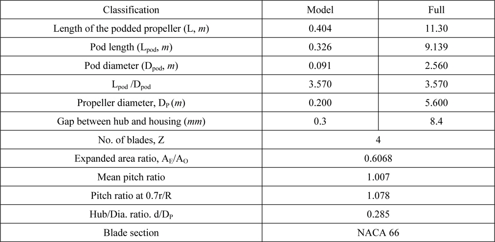
Principal dimensions of the podded propeller.
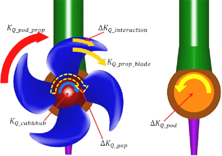
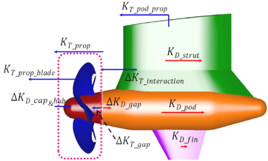
Figs. 1 and 2 show the shape of a podded propeller and various components of thrust and torque acting on its parts. The thrust and the torque are normalized as Eqs. (1) and (2), respectively. DP(


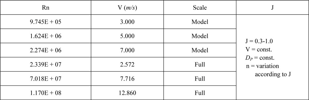
In order to investigate the effect of Reynolds number (Rn), numerical analysis is conducted for 6 Reynolds numbers from model scale to full scale. The Reynolds number is defined by the length of the podded propeller and inflow velocity (
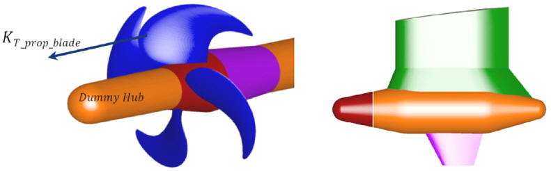
On the other hand, in order to investigate the variation of thrust and torque of podded propeller blades and the drag of pod housing by interaction between podded propeller blade and pod housing as shown Fig. 3, calculations are carried out for the propeller without pod housing and pod housing without propeller. The calculation conditions of Reynolds numbers and advance coefficients are equal to those of the podded propeller calculations. Table 2 shows the calculation conditions. The calculation for propeller without pod housing is conducted for propeller with a dummy hub as shown in Fig. 3 to obtain only the performance of propeller blades without the effects caused by other parts.
[Table 2] Calculation conditions.

Calculation conditions.
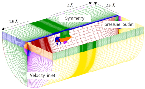
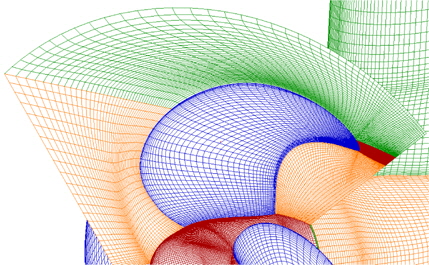
For the 3-dimensional incompressible steady state turbulent flow, the governing equations are continuity and momentum equation (RANS equation). Through a process of discretization based on the finite volume method, the algebraic equations are solved. A commercial code, Fluent (V13), is used for the computations. The convection and diffusion terms of momentum equation are discretized by QUICK and 2nd order central-difference scheme, respectively. Turbulence model is the realizable k- ε model which is popularly used for numerical analysis of ship flows, with standard wall function. SIMPLEC algorithm is used for the velocity-pressure coupling and MRF (Moving Reference Frame) scheme is adopted for propeller rotating. Fig. 4 shows the computational domain which is defined by the boundaries as follows: the inlet and the external boundaries are located at 2.5L from the hub nose and pod side, respectively, with velocity inlet condition; the outlet boundary is located at 4L from pod tail with pressure outlet condition. As a result, the 3 dimensional structured spatial grids of O-H type around the podded propeller are generated. Also, a multi-block grid for using MRF scheme is generated and then the grids are divided into two blocks of fixed block and rotating block for rotating propeller.
The number of grid applied in the numerical analysis is approximately 3.2 million; 2 million in the fixed block surrounding pod, strut, and fin, 1.2 million in the rotating block for podded propeller blades. The y+ of the first grid point away from the wall is maintained in the range of 100 to 1,200 according to the Reynolds number (Choi and Kim, 2010). The podded propeller surface grids are to be finely distributed near the propeller tip as shown in Fig. 5. The spatial grids around the propeller are composed of 4 grid blocks and each block is made of spatial grids between pressure side of reference blade and suction side of next blade.
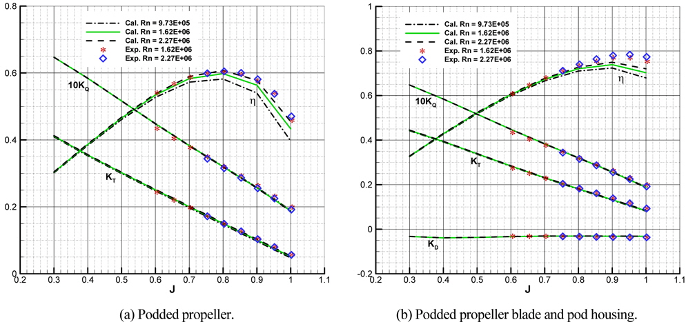
The numerical results of model scale are compared with experiments which are carried out in the large cavitation tunnel (SCAT) of Samsung Ship Model Basin (SSBM). The inflow speed of the test section is 5


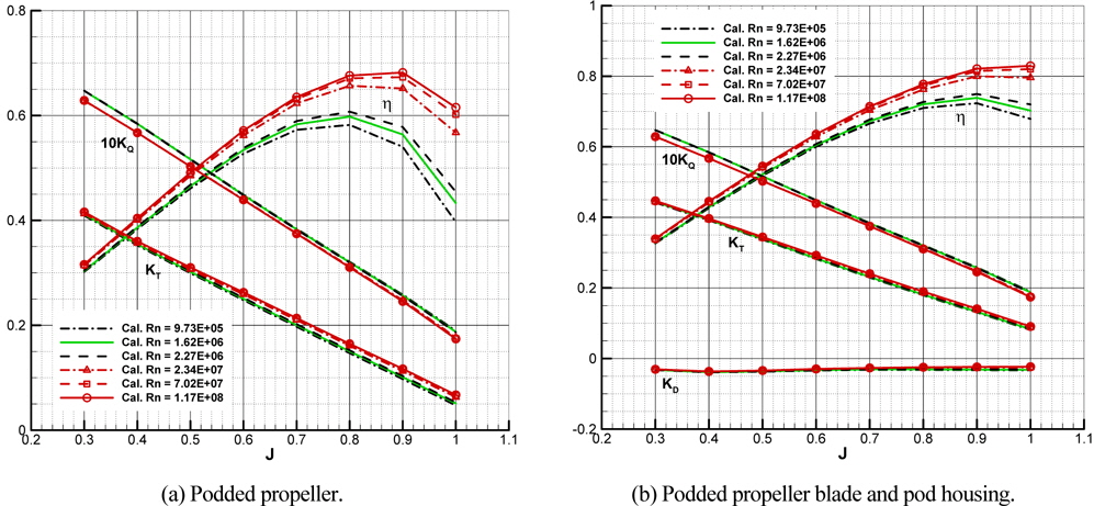
The tendency of thrust and torque for podded propeller is similar for both the calculation and the experiment but for high advance coefficients, the experimental result is higher than numerical results and the mean error between the calculation and the experiment is about 4% and near design J (=0.7). The thrust coefficient of pod housing is negative as the drag, and that is slightly decreased according to J increment in both calculation and experiment. From this, it is confirmed that the numerical analysis can be a useful tool for estimating performance of a podded propeller.
>
Scale effect and interaction in propulsive performance
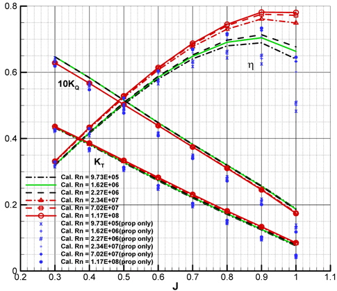
In order to investigate into the scale effect, the calculations are carried out for podded propeller from model scale to full scale Reynolds numbers. The inflow velocity is varied among 3
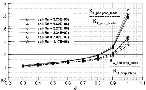
In order to verify the change of the thrust and the torque of podded propeller blade by the interaction, the calculations for propeller without pod housing are carried out and the performance of propeller blade without pod housing is compared with that of podded propeller blade. Fig. 8 shows the performance of propeller blade with and without pod housing, where, the thrust and the torque for propeller blade is defined as Eqs. (5) and (6), respectively.


The change of the performance of the podded propeller blade by Rn is similar to that of the propeller blade without pod housing, and the trust and the torque of the former are higher than those of the latter. The differences between them could be regarded as the interaction and they are represented in Fig. 9 as their ratios. The thrust and the torque ratio show a growth pattern according to increasing J due to the interaction and in high J, the rate of change is large. Maximum thrust and torque ratio are about 1.9 and 1.5 at J = 1.0 and at design J (0.7), the thrust and torque ratio is about 1.14 and 1.10, respectively. While the thrust ratio is rarely changed by Rn, the torque ratio is slightly increased by Rn and the difference is larger in high J.
The results above indicate that the interaction about podded propeller blade is influenced mainly by advance coefficient, i.e. the propeller loading, and relatively little by Reynolds number. There is, however, some effect on the torque of podded propeller blade.
And this can be inferred that it is due to the variation of the pressure field around pressure side of podded propeller blade by pod housing which is close to the podded propeller, and the angle of attack of pod housing is affected by the swirl and accelerated flow of propeller slipstream by propeller rotating. So, the interaction about podded propeller blade largely appears according to the increase of J.
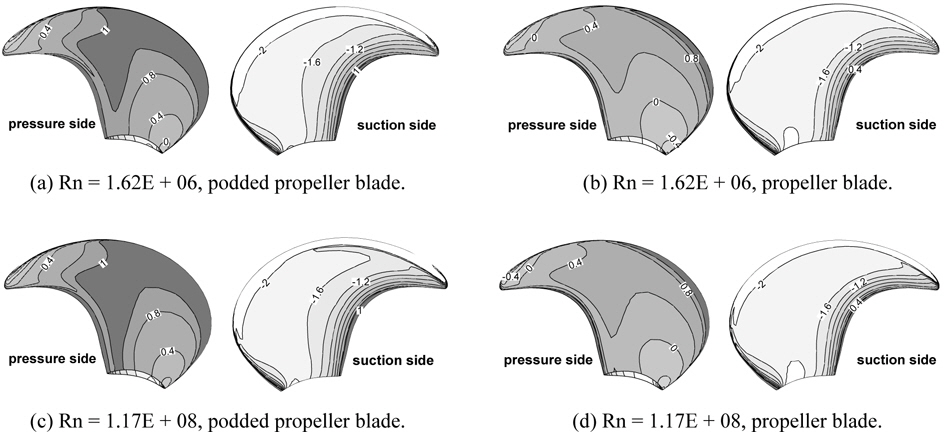
Fig. 10 shows the pressure coefficient distribution on propeller blade with and without pod housing at design J (0.7) for both model scale and full scale Reynolds number. A high pressure region of the pressure side of the podded propeller blade (a, c) is wider than that of the propeller blade without pod housing (b, d) due to the interaction. The suction side of the podded propeller blade shows that a low pressure region is smaller and the pressure recovery in trailing edge is faster than the propeller blade without pod housing. The high pressure region of pressure side of full scale (c, d) is wider than that of model scale (a, b), whereas, the low pressure region of model scale of suctions side is wider than that of full scale.
>
Scale effect and interaction in pod housing drag characteristics
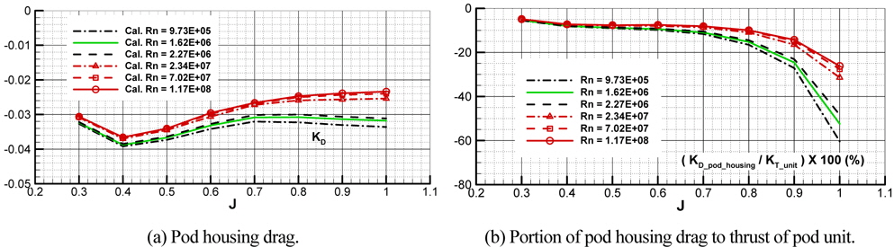
The interaction will also act in pod housing as much as the podded propeller blade, thus, the drag variation of pod housing has been investigated. Fig. 11(a) shows the drag of pod housing in larger scale than in Fig. 7(b). The
The drag ratios tend to grow as J increases and reduce as Rn increases. The rate of change of drag ratio is larger in high J than in low J. Maximum drag ratio is about 60% in the lowest Rn and about 26% in the highest Rn at J = 1.0. Also, the drag ratio is about 10% in average for Rn at design J = 0.7. This means that the drag of pod housing has considerable effect on propulsive performance of podded propeller.
In order to verify the change of pod housing drag by the interaction, the calculations for pod housing without propeller are carried out by using the same Reynolds numbers for podded propeller (Table 2). The drag (D) is normalized as Eq. (7). Because the calculation is carried out for pod housing with cab&hub except propeller, it is necessary for it to be newly defined as Eq. (8), different from Eq. (4), to compare pod housing of podded propeller and pod housing without propeller.


Swet (
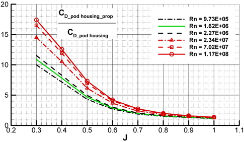
Fig. 12 shows the ratio of pod housing drag of podded propeller to that of pod housing without propeller. The drag of pod housing increases significantly than that of pod housing without propeller due to propeller rotation. For all Reynolds number, there is the tendency to decrease the ratio with increasing J, and the rate of change becomes larger in low J. The growth rate of the drag increases with Rn, and the differences of the drag by Rn are larger in low J than in high J. The drag ratio at J = 0.3 is about 17.4 in the highest Rn and about 10 in the lowest Rn. At J = 1.0, the drag ratio is similar in all of Rn, and the value is about 1.36. At the design J = 0.7, the drag increases about 2.3 times in average for Rn compared to the drag of pod housing without propeller. From the results, it is indicated that the slipstream of podded propeller is changed with the effect of Reynolds number and the interaction about pod housing is affected by not only advance coefficient but also Reynolds number.
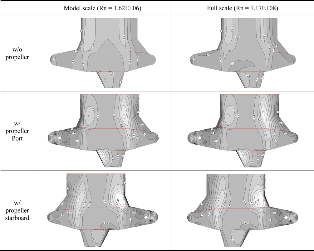
Fig. 13 shows the pressure coefficient distribution of pod housing without and with propeller in operation for model and full scale at the design J = 0.7. There are considerable differences of pressure distribution between pod housing of podded propeller and pod housing without propeller on leading and trailing edge of pod, strut and fin due to the propeller rotation. In case of propeller rotating, the pressure distributions on leading edge of strut and fin in port side appear similarly in both scale, however, those on trailing edge of strut appear that the lower pressure is distributed widely in full scale than in model scale. Also, in starboard side, the pressure distributions on leading edge of strut are similar in both scale and those on trailing edge of strut appear to be lower in model scale than in full scale.
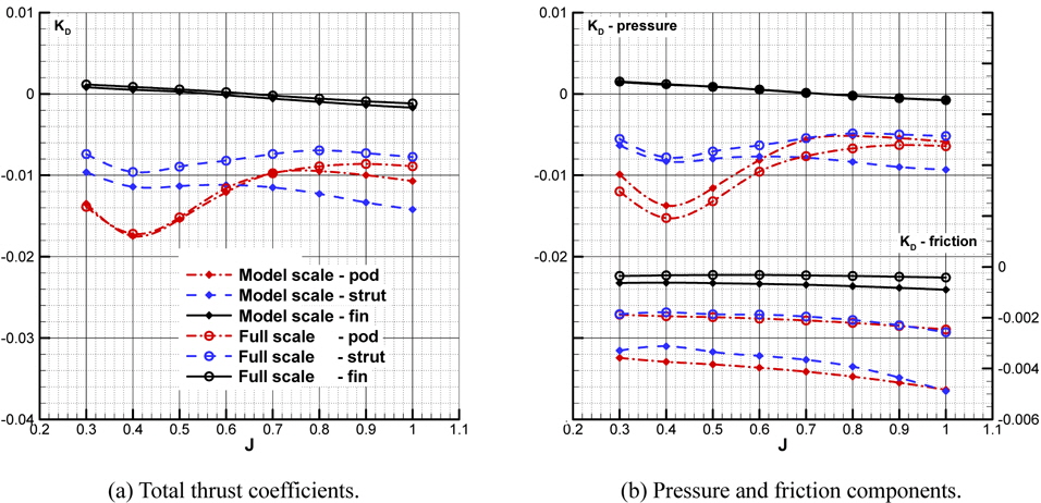
Figs. 14(a) and (b) show, respectively, the thrust coefficient and the component of pressure and friction of pod housing parts with propeller in operation for full and model scale Reynolds numbers. In case of the strut, the pressure component is smaller in full scale than in model scale. Also, the friction coefficient is smaller in full scale, as expected, so, the total thrust coefficient of the strut is much smaller in full scale. It can be reasoned from the fast pressure recovery near trailing edge and the low friction coefficient in high Reynolds number. In case of the fin, the pressure drag components of both full and model scale increase as J increases and particularly, the fin even generates thrust in some cases of low J. The friction component shows smaller friction coefficient in full scale Reynolds number. In case of the pod, in contrast with the strut, the pressure component is larger in full scale than in model scale and the difference between both shows almost constant for advance coefficients under 0.7. This would be explained that the pressure in pod tail end recovers faster in full scale as shown in Fig. 13, however, high pressure in the region of the junction between the pod tail and the strut is smaller in full scale than in model scale due to the pressure distribution in the trailing edge of the strut. The friction component of the pod is smaller in full scale and, consequently, the total thrust coefficient of pod in full scale is similar to model scale for advance coefficients under 0.7.
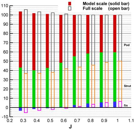
Fig. 15 shows the cumulative ratio of pod, strut and fin drag to the total pod housing drag for model (1.62E+06) and full (1.17E+08) scale Rn, respectively. These ratios show that the portion of pod is larger than other parts for low J, and for high J, becomes smaller than low J in both full and model scales. And the ratio of strut drag to total pod housing drag is smaller in full scale than model scale. However, the portion of the strut is relatively larger in full scale than model scale. So, in the pod housing design, it needs to consider a full scale performance of pod and strut.
In this paper, the CFD analysis for the tractor-type podded propeller is carried out for 6 Reynolds numbers from model scale to full scale. From the results, the scale effect by Reynolds number and interaction between podded propeller blade and pod housing by propeller loading are investigated. Firstly, it is confirmed that the numerical results of model scale agree well with the experimental results of a large cavitation tunnel and the usage of CFD analysis for estimating the performance of podded propeller is reliable at least for model scale Reynolds number.
It is found that the increments of the thrust and the torque of podded propeller blade by the interaction with pod housing are caused by the change of the slipstream of podded propeller which is altered by the pod housing. And those are mainly influenced by advance coefficient, i.e. propeller loading, which is affected relatively little by the change of Reynolds number.
On the other hand, it is confirmed that the drag of pod housing with propeller in operation is different from that of pod housing without propeller due to the acceleration and swirl of propeller slipstream which is altered by propeller loading as well as the pressure recovery and friction according to Reynolds number, which suggests that the pod housing drag under the condition of propeller in operation is the key factor of the scale effect on the performance between model and full scale podded propellers. The so called ‘drag ratio’, which is the ratio of pod housing drag to total thrust of podded propeller, increases as the advance coefficient increases due to accelerated flow in the slipstream of the podded propeller. However, the increasing rate of the drag ratio reduces continuously as the Reynolds number increases from model to full scale progressively. The pressure recovery in trailing edge of the strut and the pod appears faster in full scale than in model scale, and the friction coefficient is smaller in full scale than model scale. However, in spite of the fast pressure recovery near the pod tail end in full scale, the pressure component of the drag of pod is larger in full scale than in model scale due to the pressure distribution in the region of the junction of the pod tail which is affected by the strut.
From this study, it is confirmed that the scale effect by Reynolds number and the interaction between propeller and pod housing is quite important, and when estimating the full scale performance of podded propeller blades and pod housing for design, the consideration of scale effect and interaction is necessary. Also, this information with respect to scale effect can be used to suggest a full scale extrapolation method about the pod housing drag and, moreover, an extrapolation method for full scale performance of pod housing drag has been suggested and the method is applied for the pod housing drag ratio of model scale to full scale using CFD results of this study. The detail information can be found in Park et al. (2013).