검색 전체 메뉴
PDF
맨 위로
OA 학술지
Point Spread Function of Optical Systems Apodized by Semicircular Array of 2D Aperture Functions with Asymmetric Apodization
  • 비영리 CC BY-NC
  • 비영리 CC BY-NC
ABSTRACT

The simultaneous suppression of sidelobes and the sharpening of the central peak in the process of diffraction pattern detection based on asymmetric apodization have been investigated. Asymmetric apodization is applied to a semicircular array of two-dimensional (2D) aperture functions, which is a series of ‘coded-phase arrays of semicircular rings randomly distributed over the central circular region of a pupil function’ and is similar to that used in the field of diffractive optics. The point spread function (PSF) of an imaging system with asymmetric apodization of the discrete type has been found to possess a good side with suppressed sidelobes, whereas its bad side contains enhanced sidelobes. Further, the diffracted field characteristics are obtained in the presence of these aperture functions. Asymmetric apodization is helpful in improving the performance of the optical gratings or 2D arrays used in real-time imaging techniques.


KEYWORD
Airy pattern , Asymmetric apodization , Complex pupil , Point spread function , Resolution
  • I. INTRODUCTION

    In order to enhance the performance of an apodized optical system, we need to bring about changes in the pupil function with a relevant apodization technique. Apodization is a technique used for modifying the amplitude impulse response of an optical imaging system. Studies involving apodization have gained importance in real-time imaging experiments for various purposes [1-6]. In most of the earlier studies [1-6] on apodization, the amplitude point spread function (PSF) was perfectly symmetric in nature on both sides of the diffraction head. In 1991, Cheng and Siu [7] introduced asymmetric apodization and succeeded in achieving suppressed sidelobes and a steep central peak on one side, the so-called ‘good side,’ of the diffraction head at the cost of worsening its counterpart on the other side, the so-called ‘bad side,’ with enhanced sidelobes and a broader central peak. In a further extension of their work [8], they achieved enhanced sidelobe suppression and improved the performance of linear antenna arrays or optical gratings with asymmetric apodization [9]. Kowalczyk et al. [10] used this technique to achieve axial and lateral super-resolution in confocal scanning systems, and Granieri et al. [11] applied the same technique to an analysis using fast Fourier transform (FFT) and investigated the focusing properties of an apodized pupil function. Andres et al. [12] clearly observed the off-axis focal shift for rotationally nonsymmetric screen functions. Further, for high-reflectivity linearly chirped fiber gratings, a significant improvement in suppressing the sidelobes and smoothing the curves has been achieved by employing the asymmetric apodization technique [13]. Chollet and Goedgebuer [14] presented the experimental preparation of a LiNbO3 composed optical filter used for reducing sidelobes in the asymmetry mode. Kolpakov et al. [15] used the same technique to produce a dispersion-less Fabry–Perot fiber cavity with the use of a pair of fiber Bragg gratings. Applebuam and Chapman [16] developed a widely used technique in antenna arrays for sidelobe cancelling. It is well-known that through appropriate apodization in the exit pupil of an optical system, a PSF in the focal region may be shaped into the desired form, thereby increasing the resolving power of the instrument or optical system. This forms the basis of our investigation. We are further motivated by the work of Siu et al. [8, 9], who introduced the concept of asymmetric apodization for enhancing the resolving power of an optical system. From an in-depth analysis of the process of apodization, we have found that asymmetric apodization can result in better characteristics of the diffraction field, because it has a strong suppression effect on the sidelobes along with a sharp central peak on the good side. The work reported on asymmetric apodization suggested the idea to randomly distribute anti-phased weights to semicircular ring elements at edges, over the central circular region with uniform transmittance. We obtained some useful results by employing aperture functions in optical imaging systems for imaging point structures. A general asymmetric apodization across the pupil plane yielded significant improvement in the intensity distribution of the diffraction field. Thus, this technique has found applications in areas like optical imaging, spectroscopy, astronomy, and radar communication. In a previous paper [17], we reported the results obtained using the PSF of asymmetrically apodized optical systems with one-dimensional (1D) case-complex pupil filters. The present study generalizes this research to a 2D pupil function (semicircular arrays of the circular pupil). Following Siu et al. [9], we investigated the intensity PSF of a 2D aperture function (semicircular arrays of the circular aperture).

    II. THEORY

    According to the simplified scalar wave-diffraction theory, the amplitude PSF of a 2D apodized optical system is the Fourier transform of the pupil function.

      >  A. Figures

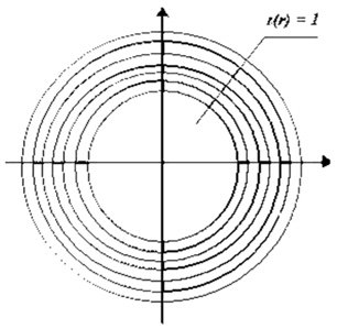
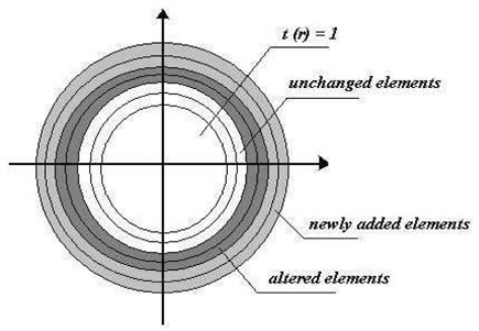
    To implement asymmetric apodization, the array of aperture is modified as: certain number of new semicircular elements are added at the left-hand side with the amplitude of 1/n, phase of i, and complex amplitude of i/n. similarly, on the right-hand side of central circular region, a certain number of new elements with the same amplitude of 1/n but with an opposite phase of i with a complex amplitude of i/n are added. Further, the complex amplitude of the left-most elements is altered to (1/n)[1-i], and similarly, that of the right-hand side elements is altered to (1/n)[1+i]. The amplitudes and the phases of other semicircular elements remain unchanged. Thus, we consider a 2D aperture with real amplitude transmittance in the central circular region and a complex conjugated semicircular array of discrete elements at the edges (Fig. 2). Fig. 1 shows the 2D array consisting of discrete elements with a circular opening, and its modified version is illustrated in Fig. 2.

      >  B. Equations

    1) The diffraction field amplitude calculated using the circular aperture of radius (1 - b):

    where sin θ, r is the coordinate in the pupil plane, z is the reduced dimensionless diffraction coordinate in the image plane, λ is the wave length of the incident radiation, θ is the angle of orientation, and t(r) is the transmittance of the central circular region of the complex pupil function.

    2) Complex amplitude calculated using the left semicircular array of discrete elements:

    3) Complex amplitude calculated using the right semicircular array of discrete elements:

    With the amplitude of each element normalized to 1/n, where , d is the separation between the elements. The total complex amplitude in the image plane is equal to the sum of the three components and the intensity PSF (I), which is a real measurable quantity obtained by taking the square modulus of the total complex amplitude on the image plane. Hence, the diffraction field amplitude in the focal region can be written as

    Thus, the intensity PSF is

    III. RESULTS AND DISCUSSION

    The results of investigations on the effect of discrete-type asymmetric apodization on the point spread function of an apodized optical imaging systems have been studied analytically from Eq. (5), as functions of the optical coordinate z varying from –12 to +12. An iterative method of numerical integration has been developed and applied to compute the positions and intensity values of the first minima (dark ring) and maxima on both sides of the detected pattern. Our focus is mainly on the positions and intensities of the central maxima, positions of the first minima, and intensities of the first optical sidelobe on the bad side of the diffraction field. These values are obtained for different conditions, and the higher-order sidelobes are neglected as they are suppressed to the zero level.

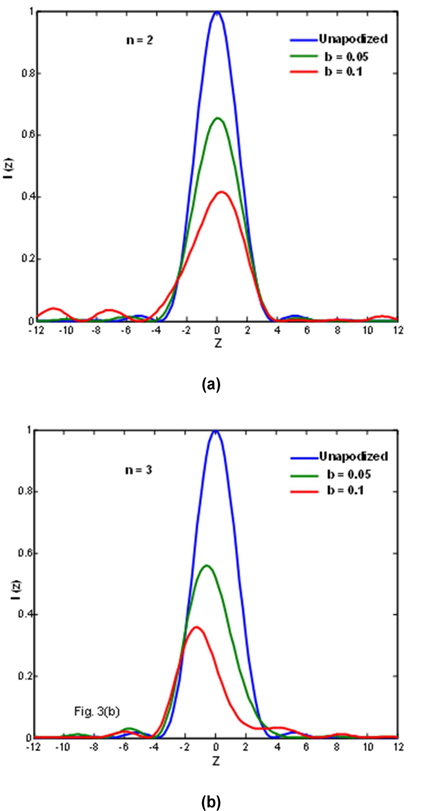
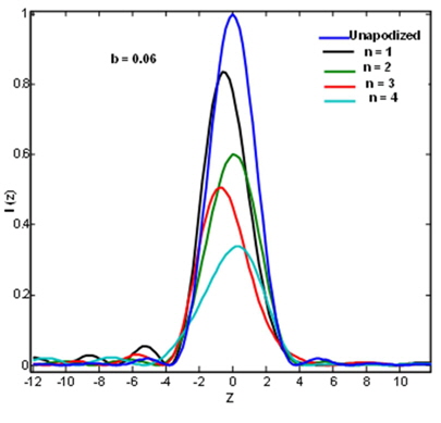
    We describe the performance of a 2D array of semicircular discrete elements with asymmetric apodization in terms of these parameters since they are the parameters used for quantifying the resolution of apodized optical imaging systems. The efficiency of the designed aperture functions is evaluated by their asymmetric PSF and is depicted in Figs. 3 and 4. In all these figures, the unapodized or airy PSF is represented by a solid blue curve for comparison with the apodized PSF curves. The PSFs shown in Fig. 3(a) and (b) are obtained for n number of semicircular elements, where n = 2 and n = 3, for different b values. Fig. 3(b) shows that on the bad side of the PSF, the central maxima is broadened and shifted, also intensity of optical sidelobes is increased. It is obtained at the cost of smoothing the good side containing the suppressed sidelobes and the narrow central maxima. This effect is further increases with b value. However, it is also observed that for a certain even number of semicircular elements over the central circular region, the axial resolution degrades with an increase in the b value. For an odd number of semicircular elements in the array, the resolution of the apodized optical system increases axially with an increase in the degree of asymmetric apodization b. This can be seen in more detail in the following figures. Fig. 4 shows the function of the reduced dimensionless diffraction coordinate z at a definite semicircular edge ring width b.

    This figure shows that the asymmetry in the image plane depends not only on the degree of asymmetric apodization at the edges of the central circular aperture but also on the number of elements in the array of the 2D aperture. The PSFs in this graph present an effect of an array of elements with discrete asymmetric apodization on the suppression of secondary optical sidelobes in the diffraction feet. In our investigation, we observed that in the presence of definite coded phase apodization for a semicircular array of discrete elements, the secondary maxima were eliminated to a large extent on the good side. Hence, it can be noted that the optimum values for the semicircular edge ring width b and n are 0.06 and 6, respectively.

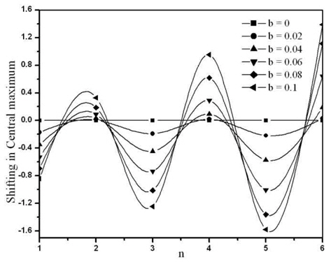
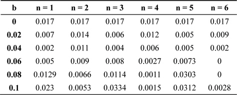
    Table 1 shows the intensity of the first secondary maxima of the diffraction pattern for different values of the semicircular edge ring width b. These values are computed for a different number of elements in the semicircular array at edges of the central circular region of aperture. The values listed in Table 1 show that for n = 1, the intensity of the secondary maxima initially decreases and then increases with an increase in the b value. For example, as b increases from 0 to 0.04, the intensity of first optical sidelobe on the good side decreases from 0.017 to 0.002. This effect is promoted on further increase in b value. A similar trend is noticed for all odd values of n, but for an even number of elements in the semicircular array of the aperture, the suppression of the first optical sidelobe increases with an increase in the asymmetric apodization controlling parameter b. For instance, for n = 2, the intensity of the first sidelobe decreases from 0.017 to 0.0053 with an increase of semicircular edge ring width b. For n = 4 or 6, the first secondary maxima is eliminated completely. It is clear from these observations that for a higher degree of apodization b = 0.06 or 0.08, the first optical sidelobe on the good side is completely eliminated. This occurs when n = 6. This is nearly 100% suppression of the optical sidelobes on the good side. This effect facilitates the detection of the direct image of a faint object, which is in close proximity of a bright object. The position of the central maximum has been computed for different values n and b and is shown in Fig. 5.

    [Table 1.] First secondary maxima intensity on the good side
    label

    First secondary maxima intensity on the good side

    This figure shows that for n = 1, 3, 5…, the position of the central maximum shifts away from the diffraction center for any value of the semicircular edge ring width b.

    For example, for b = 0.02, the central maximum position is moved from -0.169 to -0.218 with an increase in the n value; then, it moves further away from the diffraction center. The magnitude of this effect depends on the semicircular edge ring width b. On the other hand, for n = 2, 4, 6…, the central maximum position is shifted towards the good side of the PSF for all values of b.

    Fig. 5 clearly shows that the shift of the central maximum position towards the good side has a linear relation with the semicircular ring width b, for all odd values of n.

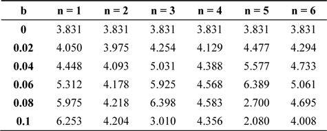
    The position of the first minimum has been investigated for different values of b with respect to z = 0 and listed in Table 2, for various numbers of elements in the semicircular array of the aperture.

    [Table 2.] First minimum position on the good side with respect to z = 0
    label

    First minimum position on the good side with respect to z = 0

    It is observed that for b = 0.02, as the even number of semicircular edge rings is increased from n = 2 to n = 6, the position of the first minimum on the good side moves away from the diffraction center. A similar trend is noticed for all odd values of semicircular edge ring n. For instance, for b = 0.02, as n increases from 1 to 5 in steps of 2, the first minimum position on the good side moves from 4.05 to 4.477.

    For b = 0.04 and b =0.06, a similar trend is noticed for all values of n. For b = 0.08, as n (odd number) increases from 1 to 5 in steps of 2, the position of the first minimum moves from 5.9754 to 6.3988 and later approaches 2.7003, i.e., close to the diffraction center.

    Further, we observed a narrowing of the central maxima on the good side of the diffraction pattern, which renders in the resolution of two point objects that have widely varying intensities. A similar trend is noted for b = 0.1, but the optimum shift in the first minima position is obtained for b = 0.08 and n = 5.

    One of the important image quality criteria is full-width at half-maximum (FWHM) of apodized optical systems with semicircular arrays; it has been computed for different numbers of semicircular discrete elements and listed in Table 3 for different values of the asymmetric apodization parameter b. These values are obtained for the airy case (b = 0) and the asymmetrically apodized case (b ≠ 0). It is observed that for n = 1, as b increases from 0 to 0.04, FWHM also increases from 3.23 to 3.2755 and then decreases with a further increase in the semicircular edge ring width b. A similar trend is observed for n = 3 and n = 5. It can be emphasized that the optimum values for b and n are 0.1 and 5, respectively. However, the magnitude of this effect depends on the number of discrete elements in the semicircular array, and for b = 0.1, this effect increases depending on the case, namely, the unapodized case or the airy case. Further, the figure reveals an asymmetry in the PSF depending on the semicircular edge ring width (b) and the number of discrete elements in the semicircular array of the pupil function. On the other hand, when b = 0.1, the dark region is observed very close to the diffraction head. This is a common effect of the super-resolver, promoted by the odd number of discrete elements in the semicircular array of the pupil function. On other hand, for n = 2 and n = 4, FWHM increases with an increase in the degree of apodization b.
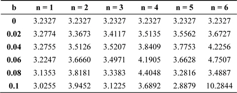
    [Table 3.] Full-wave half-maximum for different numbers of discrete elements (n) in a semicircular array of aperture with asymmetric apodization (b)

    label

    Full-wave half-maximum for different numbers of discrete elements (n) in a semicircular array of aperture with asymmetric apodization (b)

    IV. CONCLUSIONS

    We conclude that the asymmetric apodization applied to 2D arrays of elements improves the resolution of optical systems. It is more important and convenient to modify an array of discrete semicircular elements into an asymmetrically apodized one in order to achieve a simultaneous suppression of sidelobes and sharpening of the central peak in circular antenna arrays. By employing asymmetric apodization for semicircular arrays of odd number of discrete elements, the resolution of the optical imaging system has been improved considerably. Pupil function capabilities in the redistribution of energy in the sidelobes or the central peak have been verified.

    This technique is thus reliable, and the configuration of the circular aperture with semicircular arrays with opposite ends allows us to detect whether the good side is the right or the left side of the bright object and to detect the presence of the fade point object from the vicinity of the bright point object.
참고문헌
  • 1. Mills J. P., Thompson B. J. 1996 Selected Papers on Apodization: Coherent Optical Systems google
  • 2. Barakat R. 1962 “Solution of the Luneberg apodization problems,” [Journal of the Optical Society of America] Vol.52 P.264-272 google cross ref
  • 3. Mehta B. L. 1974 “Two-point resolution with non-uniform illumination by partially coherent light,” [Journal of Physics D: Applied Physics] Vol.7 P.329-333 google cross ref
  • 4. Bell R. J. 1972 Introductory Fourier Transform Spectroscopy google
  • 5. Mills J. P., Thompson B. J. 1986 “Effect of aberrations and apodization on the performance of coherent optical systems: II. Imaging,” [Journal of the Optical Society of America A] Vol.3 P.704-716 google
  • 6. Mezouari S., Harvey A. R. 2003 “Phase pupil functions for reduction of defocus and spherical aberrations,” [Optics Letters] Vol.28 P.771-773 google cross ref
  • 7. Cheng L., Siu G. G. 1991 “Asymmetric apodization,” [Measurement Science and Technology] Vol.2 P.198-202 google cross ref
  • 8. Siu G. G., Cheng L., Chiu D. S., Chan K. S. 1994 “Improved sidelobe suppression in asymmetric apodization,” [Journal of Physics D: Applied Physics] Vol.27 P.459-463 google cross ref
  • 9. Siu G. G., Cheng M., Cheng L. 1997 “Asymmetric apodization applied to linear arrays,” [Journal of Physics D: Applied Physics] Vol.30 P.787-792 google cross ref
  • 10. Kowalczyk M., Zapata-Rodriguez C. J., Martinez-Corral M. 1998 “Asymmetric apodization in confocal scanning systems,” [Applied Optics] Vol.37 P.8206-8214 google cross ref
  • 11. Granieri S., Zalvidea D., Sicre E. E. 1999 “Analysis of the asymmetric apodization using the fractional Fourier transform,” [Journal of Modern Optics] Vol.46 P.1155-1159 google
  • 12. Andres P., Martinez-Corral M., Ojeda-Castaneda J. 1993 “Off-axis focal shift for rotationally nonsymmetric screens,” [Optics Letters] Vol.18 P.1290-1292 google cross ref
  • 13. LV M. S., Feng D. J. 2009 “Analysis of chirped fiber bragg gratings with different asymmetric apodization ratios,” [Semiconductor Optoelectronics] Vol.30 P.536-540 google
  • 14. Chollet F., Goedgebuer J. P. 1998 “Improved LiNbO 3 technology for reducing sidelobe asymmetry in mode converter-based wavelength filters,” [Japanese Journal of Applied Physics] Vol.37 P.L979-L981 google
  • 15. Kolpakov S. A., Barmenkov Y. O., Aboites V. 2010 “Asymmetrically apodized fiber bragg gratings for applications in dispersion-less Fabry-Perot fiber cavities,” [Fiber and Integrated Optics] Vol.29 P.466-479 google cross ref
  • 16. Applebaum S., Chapman D. 1976 “Adaptive arrays with main beam constraints,” [IEEE Transactions on Antennas and Propagation] Vol.24 P.650-662 google cross ref
  • 17. Goud M. K., Komala R., Reddy A. N. K., Goud S. L. 2012 “Point spread function of asymmetrically apodized optical systems with complex pupil filters: the one-dimensional case with slit aperture,” [Acta Physica Polonica A] Vol.122 P.90-95 google
이미지 / 테이블
  • [ Fig. 1. ]  General scheme of the 2D semicircular array consisting of discrete elements.
    General scheme of the 2D semicircular array consisting of discrete elements.
  • [ Fig. 2. ]  Illustration of the 2D semicircular array of elements with discrete asymmetric apodization.
    Illustration of the 2D semicircular array of elements with discrete asymmetric apodization.
  • [ Fig. 3. ]  Intensity profile for different b values of semicircular edge rings with coded phase apodization. (a) n = 2, (b) n = 3.
    Intensity profile for different b values of semicircular edge rings with coded phase apodization. (a) n = 2, (b) n = 3.
  • [ Fig. 4. ]  Intensity profile for different n values in the presence of discrete asymmetric apodization of semicircular arrays.
    Intensity profile for different n values in the presence of discrete asymmetric apodization of semicircular arrays.
  • [ Table 1. ]  First secondary maxima intensity on the good side
    First secondary maxima intensity on the good side
  • [ Fig. 5. ]  Shifting of a central maximum with the number of discrete elements in the semicircular array (n) for various values of b.
    Shifting of a central maximum with the number of discrete elements in the semicircular array (n) for various values of b.
  • [ Table 2. ]  First minimum position on the good side with respect to z = 0
    First minimum position on the good side with respect to z = 0
  • [ Table 3. ]  Full-wave half-maximum for different numbers of discrete elements (n) in a semicircular array of aperture with asymmetric apodization (b)
    Full-wave half-maximum for different numbers of discrete elements (n) in a semicircular array of aperture with asymmetric apodization (b)
(우)06579 서울시 서초구 반포대로 201(반포동)
Tel. 02-537-6389 | Fax. 02-590-0571 | 문의 : oak2014@korea.kr
Copyright(c) National Library of Korea. All rights reserved.