This paper proposes a method to manipulate digital hologram contents by manipulating and/or synthesizing the depth information. To synthesize digital holograms themselves in order to create new digital hologram contents. This paper uses both the depth information obtained by converting the disparity information by using a stereo matching method and that obtained by taking pictures with a depth camera. In addition, assuming that digital holograms are created using the computer-generated holography method, we propose a technique for authoring and compositing hologram contents by using either the changes in the three-dimensional positions of objects in the hologram or by combining the objects with other contents by means of changes in the depth information. Further, more than one digital hologram was synthesized to form a hologram. The reconstructed result from the synthesized hologram also contained all the objects in each digital hologram before synthesis at the same positions and distances.
Recently, with the increasing interest in three-dimensional (3D) images, there has been a demand for solving the problems of discomfort, dizziness, etc., related to a stereo or multi-view 3D image. Therefore, research on holograms, which can realize perfect 3D imaging, has become more active. However, the high cost of generating holograms is a challenge [1].
In order to make the contents of digital holograms continuous and widespread, rather than using them as entertainment for a one-off event, it is necessary to diversify these contents. Therefore, we need to author hologram contents efficiently in order to reduce the cost and effort of content development as well as the authoring time, and to create hologram convergence contents that are applicable to various industrial fields [2]. Accordingly, a study on how to author hologram contents, such as producing hologram videos using one sheet of holograms, has been conducted previously. Currently, the development of a 3D broadcasting technology using digital holography is underway at MIT in the USA, at NHK and ATR in Japan, and at HHI in Germany.
In this paper, we discuss a measure to secure digital hologram contents. In addition, assuming that digital holograms are created using the computer-generated hologram (CGH) method, we propose a technique for authoring and compositing hologram contents by using either the changes in the 3D positions of the objects in the hologram or by combining the objects with other contents by using the changes in the depth information.
The rest of this paper is organized as follows: Section II introduces the CGH method, and Section III explains the proposed algorithm. The experimental results of the proposed algorithm are described in Section IV, and Section V presents the conclusion.
II. COMPUTER-GENERATED HOLOGRAM
A system for digital holograms uses electronic equipment such as a charge-coupled device (CCD) camera instead of an optical one to record the interference pattern of holography and transmit it as a video signal. The image is reconstructed at the receiver side by illuminating a laser beam to the received interference pattern uploaded on a spatial light modulator.
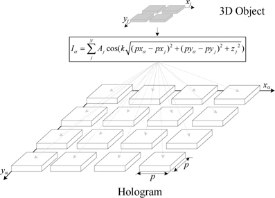
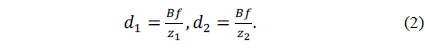
This section describes the CGH calculation method [2-5] and the method using a recursive addition system. The CGH generating equation is defined as Eq. (1):
where
Fig. 1 shows a sample coordinate array system for the 3D object and the digital hologram for the application of the CGH method, where the 3D object (light source) consists of 2 × 2 [pixel2], and the digital hologram is captured as an 4 × 4 [pixel2] image. To generate a digital hologram with this setup, the calculation of Eq. (1) must be carried out 256 (2 × 2 × 8 × 8) times.
In this section, a method for creating new digital hologram contents by a manipulation of the depth information acquired using a matching method and time-of-flight (TOF) cameras, is introduced.
>
A. Manipulation of Depth Information Acquired Using a Stereo Matching Method
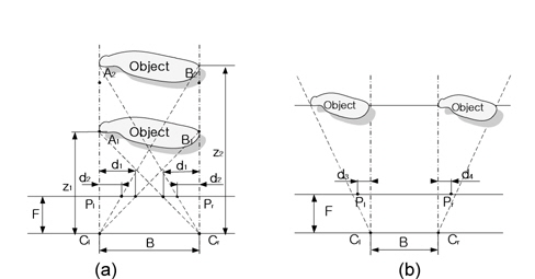
Fig. 2 shows a schematic view of the vertical and horizontal movements of objects while acquiring disparity information by using matching methods. First, for the vertical movement shown in Fig. 2(a),
The two equations can be combined to form Eq. (3):
This implies that when objects are moved from position
In addition, the size of an object projected by two cameras can be written as
Thus, when objects move vertically, the sizes of the moved objects and their disparity values are inversely proportional to distance and can be computed using Eqs. (3) and (4). In the case of the horizontal movement, as shown in Fig. 2(b), the disparity and the sizes before and after the movement remain the same. Thus, the sizes and the disparity of objects do not change when the objects move horizontally.
>
B. Manipulation of Depth Information Acquired with TOF Cameras
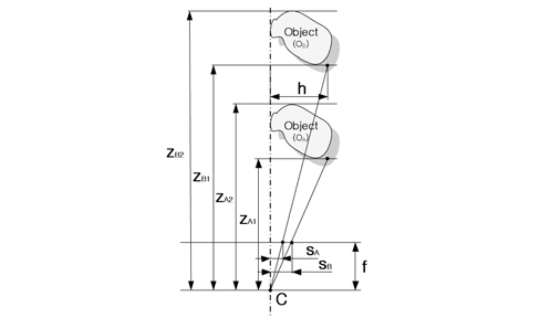
Fig. 3 shows the changes in the sizes of the depth information acquired with TOF cameras. It can be seen that the same object moves vertically. The thickness of the object does not change before and after the movement; therefore, this can be defined as Eqs. (5)–(7), as given below:
The depth information of the TOF method for the vertical movement of objects can be easily obtained using Eq. (7).
In addition, the sizes of the object on the screen,
where
In conventional 3D videos, a viewer’s attention is restricted to only a small area. In fact, it was reported that viewer can recognize 3D effect only in the limited area that they focus on directly, while the surrounding areas are actually seen as 2D effect. This is also true of holograms.
As mentioned above, considerable computation is required to create holograms, and with region of interest (ROI) processing, the computation time can be reduced.
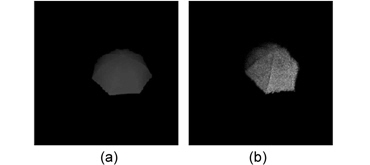
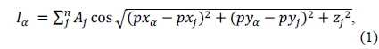
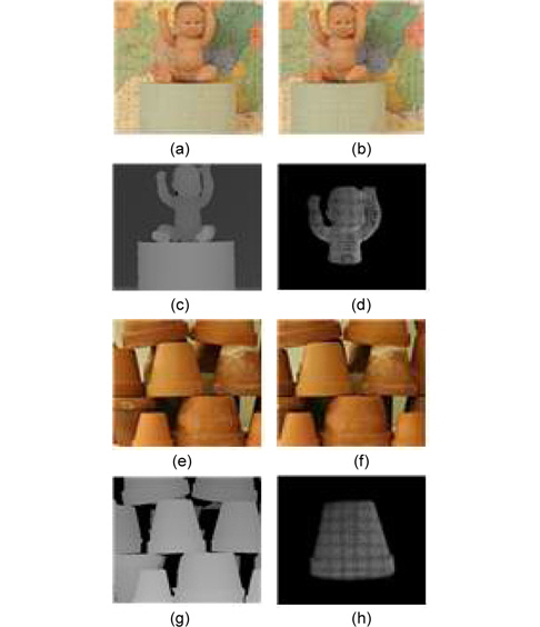
Fig. 4 shows a hologram image in which the depth information of the areas of interest and non-interest are the same, and a hologram image in which the resolution of the depth information in the non-interest area is reduced by 1/4.
Fig. 4(a) and (e) show the original image and the depth image in which the resolution of the non-interest area is reduced by 1/4, while Fig. 4(b) and (f) show the results when CGHs of Fig. 4(a) and (e) are created. The images in Fig. 4(c) and (g) are restored by focusing on the area of interest in Fig. 4(b) and (f), respectively. By comparing Fig. 4(c) and (g), we find that while the area of interest remains the same between the two images, a considerable amount of blurring is observed in the non-interest area, in the images with reduced resolution.
This is more evident in the restored images shown in Fig. 4(d) and (h), where the focus is on the non-interest area. However, a sharpness difference in the non-interest area has no significant effect when viewers pay attention only to the area of interest. On the other hand, the computational cost increases in proportion to the depth image resolution. Therefore, the size and the resolution of the non-interest area affect the computational cost of the CGH directly.
As mentioned before, in this study, we use both the disparity value and the converted depth value via the matching method to author the digital hologram contents. To restore an original image from the digital hologram, a simulation technique was employed. Experimental images provided in the Middlebury site were used for the depth information of the matching method. Note that these images were acquired using Canon G1. Two test images of a baby and flower pots are shown in Fig. 5. Here, Fig. 5(a) and (e) are left images, while Fig. 5(b) and (f) are right images.
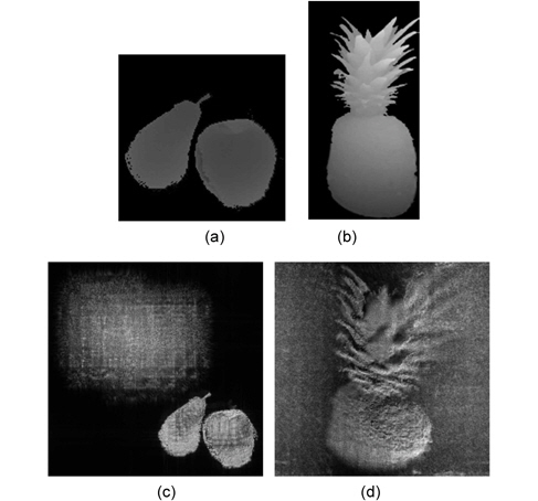
Fig. 5(c) and (g) display the disparity information provided in the Middlebury site. In addition, Fig. 5(d) and (h) are images restored by the simulation method, from the digital holograms created using Eq. (1), as a specific object is extracted from the image. In order to acquire the depth information directly by using a depth camera of the TOF method, a SR4000 depth camera of the MESA Imaging Company (Zurich, Switzerland) was used to take a picture. Fig. 6 shows an example of how to create holograms with the depth camera by using the depth information shot and then restore them by using the simulation method.
1) Manipulation of Depth Information by Using the Stereo Matching Method
Sections of the object were extracted from the depth information converted from the disparity information, acquired using the matching method. The result was then manipulated to have the position to move, thereby creating digital holograms and restoring the results. As shown in the example in Fig. 7, the distance movement was shown since movement without distance change is a simple coordinate transformation in the position movement. The distance in Fig. 7(a) from the object center is about 80 cm, while in Fig. 7(d), this changes to 100 cm. Fig. 7(b) and (c) show the images restored from the holograms created from Fig. 7(a), while Fig. 7(e) and (f) show the images restored from the holograms created from Fig. 7(d). Among them, Fig. 7(b) and (e) have their restoration distances set to the object center in Fig. 7(a), while Fig. 7(c) and (f) have their restoration distances set to the object center in Fig. 7(b). That is, they refer to a distance from the restored images to the corresponding object.
2) Manipulation of Depth Information Acquired with Depth Camera
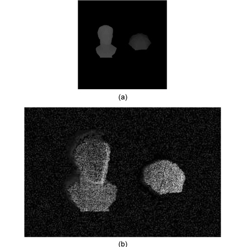
The depth images shot with the depth camera of the TOF method are also manipulated using the same procedure as the depth information obtained by the matching method. Fig. 8 shows an example of the manipulation of the depth information acquired with the TOF depth cameras. The procedure employed is the same as that shown in Fig. 7.
In this paper, in order to create new digital hologram contents, we utilized depth information acquired using a depth camera of the TOF method and the stereo matching method. Furthermore, we combined the contents by analyzing the characteristics of the creation of depth information of such contents and created depth information by changing the object positions. In addition, the linearity of the hologram of each individual object in the hologram area was verified with experiments and each hologram of an object was created using the verified linearity characteristics, thereby compositing newly acquired holograms with the existing holograms to create new contents.